- Table of Contents
-
- H3C Campus Fixed-Port Switches Web-Based Quick Start Configuration Guide-6W100
- 01-Compatible Product Models
- 02-Configuring Web Login with the Default IP
- 03-Web Login to a Device Without a Default IP
- 04-Interface Settings
- 05-PoE
- 06-VLAN
- 07-DHCP Server
- 08-DHCP Relay Agent
- 09-Static Routing
- 10-Policy-Based Routing
- 11-Ethernet Link Aggregation
- 12-Port Mirroring
- 13-Packet Filtering
- 14-Interface Rate Limit
- 15-Traffic Constrain
- 16-Spanning Tree
- 17-Direct Portal Authentication
- 18-Port Security
- 19-Port Isolation
- 20-ARP Attack Protection
- 21-Configuring a Static ARP Entry
- 22-IGMP Snooping
- 23-Enabling IPSG on an Interface
- 24-Software Upgrade
- 25-Adding Administrator Accounts
- 26-Ping and Tracert
- 27-Password Change
- 28-System Time
- 29-System Log
- 30-Configuration Backup, Export, Restoration to Factory Default
- 31-Device Reboot
- 32-Small-Sized Campus Network Configuration Guide
- Related Documents
-
| Title | Size | Download |
|---|---|---|
| 25-Adding Administrator Accounts | 153.31 KB |
Quick Start Configuration Guide for Adding Administrator Accounts
Network configuration
On Switch, add an administrator account. A user can use this account to log in to Switch through HTTP. The requirements are as follows:
· When a user uses the administrator account to log in, Switch performs local authentication for the user.
· The administrator account name is webuser, and the password is 12345.
· After the user passes authentication, the user will be assigned the role of network-admin.
Figure 1 Network diagram

Procedure
1. Configure VLANs and VLAN interfaces:
a. From the left navigation pane, select Network > Links > VLAN.
The VLAN page opens.
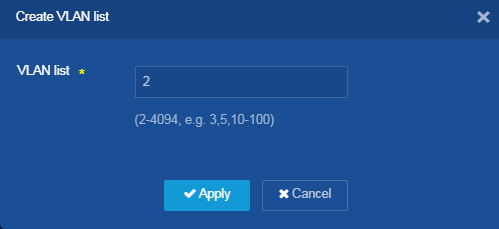
b. Click the Create icon ![]() in the right. On the Create VLAN list
page that opens, enter 2 in the VLAN list field,
and click Apply.
in the right. On the Create VLAN list
page that opens, enter 2 in the VLAN list field,
and click Apply.
Figure 2 Creating a VLAN
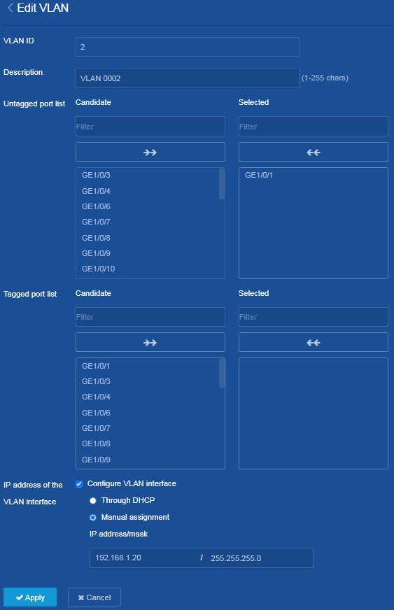
c. Click the Edit icon ![]() in the right of VLAN 2 to enter the Edit VLAN
page.
in the right of VLAN 2 to enter the Edit VLAN
page.
d. Add the interface that connects to the administrator’s PC to the untagged port list of VLAN 2.
e. In the IP address of the VLAN interface area, select Configure VLAN interface, and assign IP address 192.168.1.20 and mask 255.255.255.0 to the VLAN interface.
f. Click Apply.
The system displays a success message after it configures the VLAN and VLAN interface.
Figure 3 Configuring VLANs and VLAN interfaces
2. Configure an administrator account:
a. From the left navigation pane, select Device > Maintenance >Administrators.
The Administrators page opens.
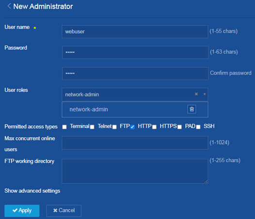
b. On this page, perform the following tasks:
- Click the Add icon ![]() to add an administrator.
to add an administrator.
- Configure the username as webuser.
- Configure the password as 12345.
- Select network-admin from the User roles list.
- Select HTTP for the Permitted access types field.
- Click Apply.
The system displays a success message after it adds the administrator account.
Figure 4 Add an administrator account
3. Enable the HTTP and HTTPS services:
a. From the left navigation pane, select Network > Service > HTTP/HTTPS.
The Network Service page opens.
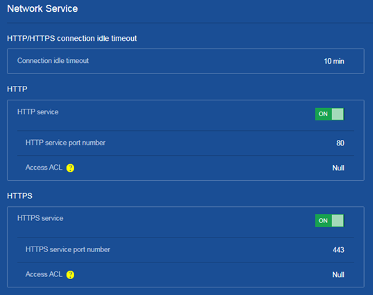
b. On this page, perform the following tasks:
- Click ON for HTTP service to enable the HTTP login service.
- Click ON for HTTPS service to enable the HTTPS login service.
The system displays a success message after it enables the HTTP login service and the HTTPS login service.
Figure 5 Enabling the HTTP and HTTPS services
4. Save the configuration.
Click the Save icon ![]() at the upper left of the page.
at the upper left of the page.
Verifying the configuration
1. Verify that you can see the added administrator account on the Administrators page.
2. On your PC, enter http://192.168.1.20 in the address bar of a browser. The Web login page opens. On the login page, enter the administrator account name, password, and verification code. Verify that you can successfully log in to the Web page of the device and configure related settings.
