- Table of Contents
-
- H3C Campus Fixed-Port Switches Web-Based Quick Start Configuration Guide-6W100
- 01-Compatible Product Models
- 02-Configuring Web Login with the Default IP
- 03-Web Login to a Device Without a Default IP
- 04-Interface Settings
- 05-PoE
- 06-VLAN
- 07-DHCP Server
- 08-DHCP Relay Agent
- 09-Static Routing
- 10-Policy-Based Routing
- 11-Ethernet Link Aggregation
- 12-Port Mirroring
- 13-Packet Filtering
- 14-Interface Rate Limit
- 15-Traffic Constrain
- 16-Spanning Tree
- 17-Direct Portal Authentication
- 18-Port Security
- 19-Port Isolation
- 20-ARP Attack Protection
- 21-Configuring a Static ARP Entry
- 22-IGMP Snooping
- 23-Enabling IPSG on an Interface
- 24-Software Upgrade
- 25-Adding Administrator Accounts
- 26-Ping and Tracert
- 27-Password Change
- 28-System Time
- 29-System Log
- 30-Configuration Backup, Export, Restoration to Factory Default
- 31-Device Reboot
- 32-Small-Sized Campus Network Configuration Guide
- Related Documents
-
| Title | Size | Download |
|---|---|---|
| 07-DHCP Server | 248.50 KB |
DHCP Server Quick Start Configuration Guide
Network configuration
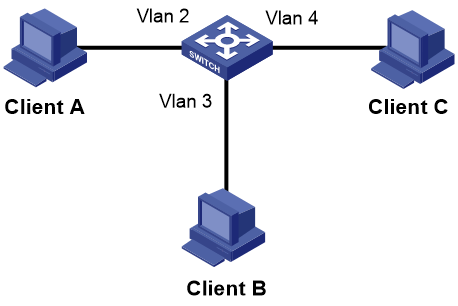
As shown in Figure 1, department A uses VLAN 2, department B uses VLAN 3, and department C uses VLAN 4. Configure the core switch as a DHCP server for dynamic IP address assignment to the hosts in department A, department B, and department C.
Procedure
1. Configure VLAN.
a. From the left navigation pane, select Network > Links > VLAN.
b. On the page that opens, click the create icon ![]() to
create VLAN 2.
to
create VLAN 2.
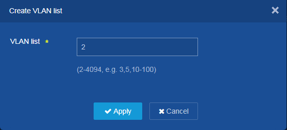
c. Add VLAN 2 to the VLAN list, and then click Apply.
Figure 2 Creating VLAN 2
d. Click the edit icon ![]() on the right of VLAN 2 to edit the settings of VLAN 2.
on the right of VLAN 2 to edit the settings of VLAN 2.
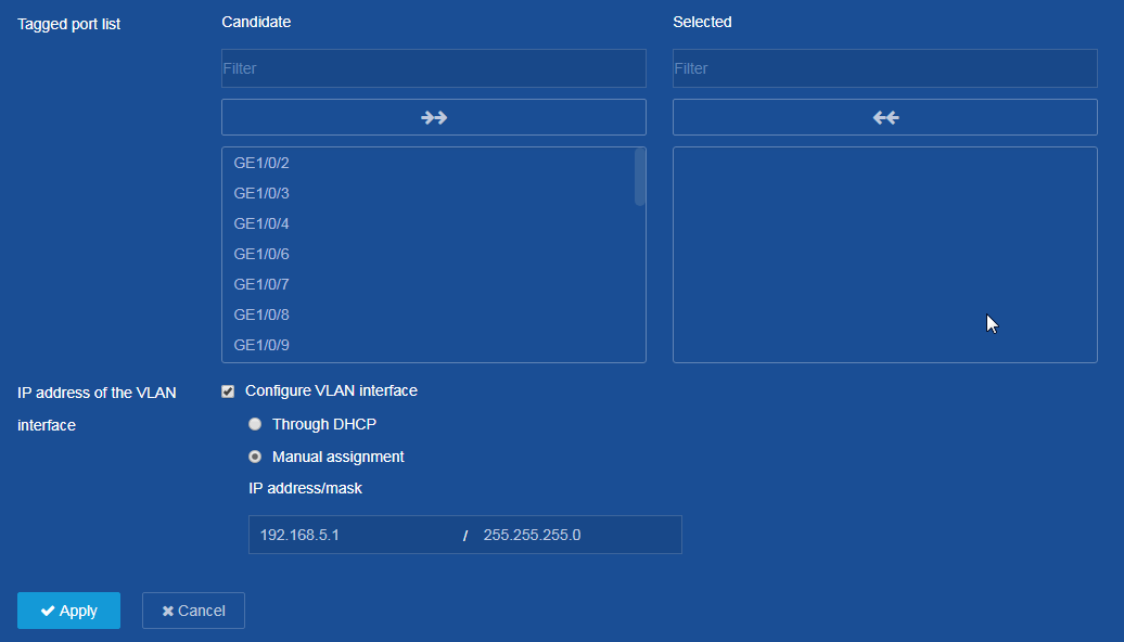
e. Add GE1/0/2 to the untagged port list of VLAN 2.
f. Select Configure VLAN interface at the IP address of the VLAN interface parameter.
g. Assign IP address 192.168.5.1 and subnet mask 255.255.255.0 to VLAN-interface 2.
Figure 3 Configuring VLAN 2
h. Click Apply.
The system displays a success message if you configure VLAN 2 successfully.
i. Configure VLAN 3 and VLAN 4 in the same way as you configure VLAN 2. Details are not shown.
2. Create DHCP address pool.
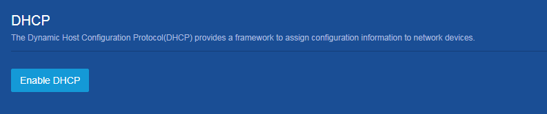
a. From the left navigation pane, select Network > Service > DHCP.
b. On the page that opens, click Enable DHCP.
Figure 4 Enabling DHCP
c. Click Address pool at the upper right of the DHCP configuration page, and then click Add Address Pool to create DHCP address pool 1.
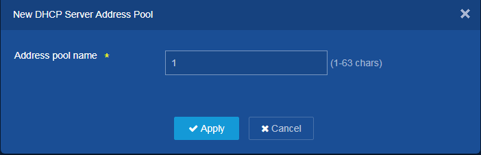
Figure 5 Adding DHCP address pool
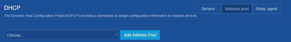
Figure 6 Creating DHCP address pool 1
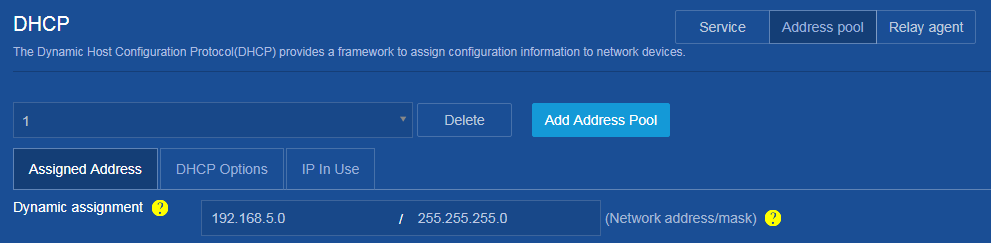
d. Click the Address Assignment tab. On the page, specify IP address range 192.168.5.0/24 for dynamic address assignment in DHCP address pool 1.
Figure 7 Specifying IP address range for dynamic address assignment
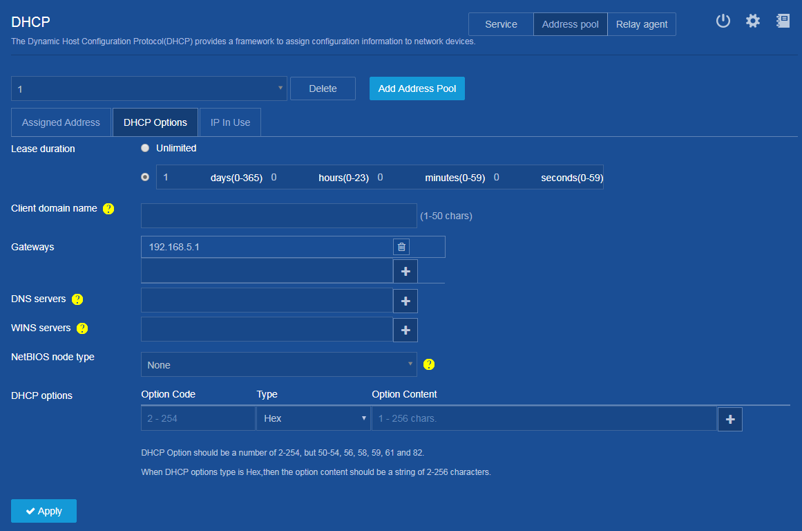
e. Click the DHCP Options
tab, enter 192.168.5.1 as the
gateway in DHCP address pool 1,
and then click the add icon ![]() .
.
f. Click Apply. The system displays a success message if you configure DHCP address pool 1 successfully.
Figure 8 Specifying gateway in DHCP address pool 1
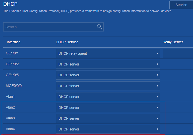
3. Configuring VLAN interfaces to operate in DHCP server mode.
a. From the left navigation pane, select Network > Service > DHCP.
b. On the page that opens, set the DHCP service type to DHCP server for VLAN-interface 2, VLAN-interface 3, and VLAN-interface 4. By default, an interface operates in DHCP server mode.
Figure 9 Configuring DHCP server mode
c. Click the ![]() icon on the top right of the page to configure advanced DHCP
settings. On the page that opens, set the maximum number of ping packets to 1
and the ping response timeout time to 500 milliseconds.
icon on the top right of the page to configure advanced DHCP
settings. On the page that opens, set the maximum number of ping packets to 1
and the ping response timeout time to 500 milliseconds.
Figure 10 Configuring advanced DHCP settings

d. Click Apply. The system displays a success message if you configure the advanced DHCP settings successfully.
4. Save the configuration.
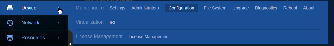
a. From the left navigation pane, select Device > Configuration.
Figure 11 Entering configuration file page
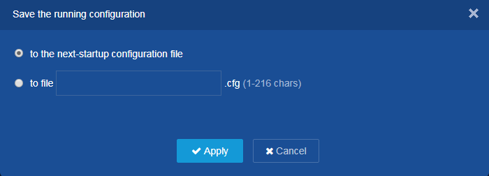
b. Click Saving Running Configuration, and then save the running configuration to the next-startup configuration file or to a specific file.
If you save the running configuration to a specific file, the system uses the file as the next-startup configuration file.
c. Click Apply.
Figure 12 Saving running configuration
Verifying the configuration
Verify that the switch can dynamically assign an IP address from the desired subnet to Client A, Client B, or Client C.
To view the IP addresses assigned by the DHCP server, perform the following tasks:
1. From the left navigation pane on the switch configuration page, select Network > Service > DHCP.
2. Click Address pool at the upper right of the DHCP configuration page.
3. Click the IP in Use tab.
