- Table of Contents
-
- H3C Access Controllers and Access Points Configuration Examples(V7)-6W101
- 00-Preface
- 01-H3C Access Controllers AP's Association with the AC at Layer 2 Configuration Examples
- 02-H3C Access Controllers Comware 7 AP's Association with the AC at Layer 2 (IPv6) Configuration Examples
- 03-H3C Access Controllers AP's Association with the AC at Layer 3 Configuration Examples
- 04-H3C Access Controllers Comware 7 AP's Association with the AC at Layer 3 (IPv6) Configuration Examples
- 05-H3C Access Controllers Local MAC Authentication Configuration Examples (V7)
- 06-H3C Access Controllers MAC Authentication with Guest VLAN Assignment Configuration Examples (V7)
- 07-H3C Access Controllers Comware 7 MAC Authentication with Guest VLAN Assignment (IPv6) Configuration Examples
- 08-H3C Access Controllers MAC Authentication and PSK Authentication Configuration Examples (V7)
- 09-H3C Access Controllers Auto AP Configuration Examples (V7)
- 10-H3C Access Controllers WLAN Load Balancing Configuration Examples (V7)
- 11-H3C Access Controllers WEP Encryption Configuration Examples
- 12-H3C Access Controllers Local Forwarding Configuration Examples
- 13-H3C Access Controllers Layer 2 Static Aggregation Configuration Examples (V7)
- 14-H3C Access Controllers Remote 802.1X Authentication Configuration Examples (V7)
- 15-H3C Access Controllers Comware 7 Remote 802.1X Authentication (IPv6) Configuration Examples
- 16-H3C Access Controllers 802.1X Authentication with ACL Assignment Through IMC Server @CE@ (V7)
- 17-H3C Access Controllers 802.1X Authentication with User Profile Assignment Through IMC Server @CE@ (V7)
- 18-H3C Access Controllers EAD Authentication Configuration Examples (V7)
- 19-H3C Access Controllers Comware 7 EAD Authentication (IPv6) Configuration Examples
- 20-H3C Access Controllers Remote Portal Authenticaiton Configuration Examples (V7)
- 21-H3C Access Controllers Comware 7 Remote Portal Authenticaiton (IPv6) Configuration Examples
- 22-H3C Access Controllers Local Portal Authentication Configuration Examples (V7)
- 23-H3C Access Controllers Comware 7 Local Portal Authentication (IPv6) Configuration Examples
- 24-H3C Access Controllers Local Forwarding Mode Direct Portal Authentication Configuration Examples (V7)
- 25-H3C Access Controllers Local Forwarding Mode Direct Portal Authentication (IPv6) Configuration Examples(V7)
- 26-H3C Access Controllers Local Portal Authentication through LDAP Server Configuration Examples (V7)
- 27-H3C Access Controllers Local Portal Authentication through LDAP Server (IPv6) Configuration Examples(V7)
- 28-H3C Access Controllers MAC-based Portal Quick Authenticaiton Configuration Example (V7)
- 29-H3C Access Controllers Comware 7 MAC-based Quick Portal Authenticaiton (IPv6) Configuration Example
- 30-H3C Access Controllers SSH Configuration Examples (7)
- 31-H3C Access Controllers Internal-to-External Access Through NAT Configuration Examples (V7)
- 32-H3C Access Controllers Static Blacklist Configuration Examples
- 33-H3C Access Controllers Comware 7 WLAN Access (IPv6) Configuration Examples
- 34-H3C Access Controllers Inter-AC Roaming Configuration Examples (V7)
- 35-H3C Access Controllers Comware 7 Inter-AC Roaming (IPv6) Configuration Examples
- 36-H3C Access Controllers HTTPS Login Configuration Examples (V7)
- 37-H3C Access Controllers Client Rate Limiting Configuration Examples (V7)
- 38-H3C Access Controllers Client Quantity Control Configuration Examples
- 39-H3C Access Controllers Medical RFID Tag Management Configuration Examples (V7)
- 40-H3C Access Controllers iBeacon Management Configuration Examples (V7)
- 41-H3C Access Controllers Remote AP Configuration Examples (V7)
- 42-H3C Access Controllers PSK Encryption Configuration Examples
- 43-H3C Access Controllers WIPS Configuration Examples (V7)
- 44-H3C Access Controllers Layer 2 Multicast Configuration Example (V7)
- 45-H3C Access Controllers IRF Setup with Members Directly Connected Configuration Examples (V7)
- 46-H3C Access Controllers IRF Setup with Members Not Directly Connected Configuration Examples (V7)
- 47-H3C Access Controller Modules IRF Setup with Members in One Chassis Configuration Examples (V7)
- 48-H3C Access Controller Modules IRF Setup with Members in Different Chassis Configuration Examples (V7)
- 49-H3C Access Controllers Comware 7 IP Source Guard (IPv6) Configuration Examples
- 50-Policy-Based Forwarding with Dual Gateways Configuration Example
- 51-H3C Access Controllers Comware 7 Policy-Based Forwarding with Dual Gateways (IPv6) Configuration Example
- 52-Policy-Based Local Forwarding Configuration Examples
- Related Documents
-
| Title | Size | Download |
|---|---|---|
| 18-H3C Access Controllers EAD Authentication Configuration Examples (V7) | 550.84 KB |
|
|
|
H3C Access Controllers |
|
Comware 7 EAD Authentication |
|
Configuration Examples |
Copyright © 2019 New H3C Technologies Co., Ltd. All rights reserved.
No part of this manual may be reproduced or transmitted in any form or by any means without prior written consent of New H3C Technologies Co., Ltd.
Except for the trademarks of New H3C Technologies Co., Ltd., any trademarks that may be mentioned in this document are the property of their respective owners.
The information in this document is subject to change without notice.
Contents
Example: Configuring EAD authentication
Introduction
This document provides an example for configuring EAD authentication for wireless clients.
Prerequisites
This document applies to Comware 7-based access controllers and access points. Procedures and information in the examples might be slightly different depending on the software or hardware version of the access controllers and access points.
The configuration examples in this document were created and verified in a lab environment, and all the devices were started with the factory default configuration. When you are working on a live network, make sure you understand the potential impact of every command on your network.
This document assumes that you have basic knowledge of WLAN access and EAD authentication.
Example: Configuring EAD authentication
Network configuration
As shown in Figure 1, the switch acts as the DHCP server to assign IP addresses to the AP and the client. Configure EAD authentication on the AC to authenticate the client.

Restrictions and guidelines
Use the serial ID labeled on the AP's rear panel to specify an AP.
Procedures
Configuring the AC
1. Configure interfaces on the AC:
# Create VLAN 100 and VLAN-interface 100, and assign an IP address to the VLAN interface. The AC will use this IP address to establish a CAPWAP tunnel with the AP.
<AC> system-view
[AC] vlan 100
[AC-vlan100] quit
[AC] interface vlan-interface 100
[AC-Vlan-interface100] ip address 192.1.1.1 16
[AC-Vlan-interface100] quit
# Create VLAN 200 and VLAN-interface 200, and assign an IP address to the VLAN interface. The client will use VLAN 200 to access the WLAN.
[AC] vlan 200
[AC-vlan200] quit
[AC] interface vlan-interface 200
[AC-Vlan-interface200] ip address 192.2.1.1 24
[AC-Vlan-interface200] quit
# Configure GigabitEthernet 1/0/1 that connects the AC to the switch as a trunk port, assign the port to VLAN 100 and VLAN 200, and remove the port from VLAN1. Set the PVID of the port to VLAN 100.
[AC] interface gigabitethernet 1/0/1
[AC-GigabitEthernet1/0/1] port link-type trunk
[AC-GigabitEthernet1/0/1] undo port trunk permit vlan 1
[AC-GigabitEthernet1/0/1] port trunk permit vlan 100 200
[AC-GigabitEthernet1/0/1] port trunk pvid vlan 100
[AC-GigabitEthernet1/0/1] quit
2. Enable port security and specify the EAP relay mode for 802.1X authentication.
[AC] port-security enable
[AC] dot1x authentication-method eap
3. Configure a RADIUS scheme:
# Create a RADIUS scheme named radius1 and enter its view.
[AC] radius scheme radius1
# Specify the IP addresses of the primary authentication and accounting RADIUS servers.
[AC-radius-radius1] primary authentication 8.1.1.16
[AC-radius-radius1] primary accounting 8.1.1.16
# Set the shared key to example in plaintext form for secure communication with the servers.
[AC-radius-radius1] key authentication simple example
[AC-radius-radius1] key accounting simple example
# Set the real-time accounting interval to 3 minutes.
[AC-radius-radius1] timer realtime-accounting 3
# Specify IP address 192.1.1.1 as the source IP address for outgoing RADIUS packets.
[AC-radius-radius1] nas-ip 192.1.1.1
4. Configure an authentication domain:
# Create an ISP domain named radius1 and enter its view.
[AC] domain radius1
# Apply RADIUS scheme radius1 to ISP domain radius1 for authentication, authorization, and accounting.
[AC-isp-radius1] authentication lan-access radius-scheme radius1
[AC-isp-radius1] authorization lan-access radius-scheme radius1
[AC-isp-radius1] accounting lan-access radius-scheme radius1
5. Configure ACLs:
# Create IPv4 advanced ACL 3000 and enter its view.
[AC] acl advanced 3000
# Create an ACL rule to permit all IP packets.
[AC-acl-ipv4-adv-3000] rule permit ip
[AC-acl-ipv4-adv-3000] quit
# Create IPv4 advanced ACL 3001 and enter its view.
[AC] acl advanced 3001
# Create an ACL rule to permit all UDP packets.
[AC-acl-ipv4-adv-3001] rule permit udp
# Create an ACL rule to deny all TCP packets.
[AC-acl-ipv4-adv-3001] rule deny tcp
[AC-acl-ipv4-adv-3001] quit
6. Configure a wireless service:
# Create a service template named 1 and enter its view.
[AC] wlan service-template 1
# Configure the SSID of the service template as service.
[AC-wlan-st-service] ssid service
# Assign clients coming online through the service template to VLAN 200.
[AC-wlan-st-1] vlan 200
# Set the AKM mode to 802.1X.
[AC-wlan-st-1] akm mode dot1x
# Set the CCMP cipher suite for frame encryption and enable the RSN-IE in the beacon and probe responses.
[AC-wlan-st-1] cipher-suite ccmp
[AC-wlan-st-1] security-ie rsn
# Set the authentication mode to 802.1X.
[AC-wlan-st-1] client-security authentication-mode dot1x
# Specify ISP domain radius1 for authenticating 802.1X clients.
[AC-wlan-st-1] dot1x domain radius1
# Enable the service template.
[AC-wlan-st-1] service-template enable
[AC-wlan-st-1] quit
7. Configure an AP:
# Create an AP named officeap with model WA4320i-ACN,
[AC] wlan ap officeap model WA4320i-CAN
# Set the serial ID of the AP to 210235A1K6C15A003025.
[AC-wlan-ap-officeap] serial-id 210235A1K6C15A003025
# Enter the view of radio 2 and bind service template 1 to radio 2.
[AC-wlan-ap-officeap] radio 2
[AC-wlan-ap-officeap-radio-2] service-template 1
# Enable radio 2.
[AC-wlan-ap-officeap-radio-2] radio enable
[AC-wlan-ap-officeap-radio-2] quit
[AC-wlan-ap-officeap] quit
8. Configure a static route destined for the RADIUS server:
[AC] ip route-static 8.0.0.0 8 192.2.1.2
Configuring the switch
1. Configure interfaces on the switch:
# Create VLAN 100 and VLAN-interface 100, and assign an IP address to the VLAN interface. The switch will use this VLAN to forward CAPWAP packets between the AC and the AP.
<Switch> system-view
[Switch] vlan 100
[Switch-vlan100] quit
[Switch] interface vlan-interface 100
[Switch-Vlan-interface100] ip address 192.1.1.2 16
[Switch-Vlan-interface100] quit
# Create VLAN 200 and VLAN-interface 200, and assign an IP address to the VLAN interface. The switch will use this VLAN to forward client traffic.
[Switch] vlan 200
[Switch-vlan200] quit
[Switch] interface vlan-interface 200
[Switch-Vlan-interface200] ip address 192.2.1.2 24
[Switch-Vlan-interface200] quit
# Create VLAN 8 and VLAN-interface 8, and assign an IP address to the VLAN interface. The switch will use this VLAN to communicate with the RADIUS server.
[Switch] vlan 8
[Switch-vlan8] quit
[Switch] interface vlan-interface 8
[Switch-Vlan-interface8] ip address 8.1.1.2 8
[Switch-Vlan-interface8] quit
# Configure GigabitEthernet 1/0/1 that connects the switch to the AC as a trunk port, assign the port to VLAN 100 and VLAN 200, and remove the port from VLAN 1. Set the PVID of the port to VLAN 100.
[Switch] interface gigabitethernet 1/0/1
[Switch-GigabitEthernet1/0/1] port link-type trunk
[Switch-GigabitEthernet1/0/1] undo port trunk permit vlan 1
[Switch-GigabitEthernet1/0/1] port trunk permit vlan 100 200
[Switch-GigabitEthernet1/0/1] port trunk pvid vlan 100
[Switch-GigabitEthernet1/0/1] quit
# Configure GigabitEthernet 1/0/2 that connects the switch to the AP as an access port, assign the port to VLAN 100 and VLAN 200, and remove the port from VLAN 1. Set the PVID of the port to VLAN 100.
[Switch] interface gigabitethernet 1/0/2
[Switch-GigabitEthernet1/0/2] port link-type trunk
[Switch-GigabitEthernet1/0/2] undo port trunk permit vlan 1
[Switch-GigabitEthernet1/0/2] port trunk permit vlan 100 200
[Switch-GigabitEthernet1/0/2] port trunk pvid vlan 100
# Enable PoE on GigabitEthernet 1/0/2.
[Switch-GigabitEthernet1/0/2] poe enable
[Switch-GigabitEthernet1/0/2] quit
# Configure GigabitEthernet 1/0/3 that connects the switch to the RADIUS server as a trunk port, assign the port to VLAN 100 and VLAN 200, and remove the port from VLAN 1. Set the PVID of the port to VLAN 8.
[Switch] interface gigabitethernet 1/0/3
[Switch-GigabitEthernet1/0/3] port link-type trunk
[Switch-GigabitEthernet1/0/3] undo port trunk permit vlan 1
[Switch-GigabitEthernet1/0/3] port trunk permit vlan 100 200
[Switch-GigabitEthernet1/0/3] port trunk pvid vlan 8
2. Configure the DHCP service:
# Enable DHCP.
[Switch] dhcp enable
# Create a DHCP address pool named vlan100, and specify subnet 192.1.0.0/16 for dynamic allocation.
[Switch] dhcp server ip-pool vlan100
[Switch-dhcp-pool-vlan100] network 192.1.0.0 mask 255.255.255.0
# Exclude 192.1.1.1 from dynamic allocation and specify gateway IP address 192.1.1.2 for DHCP address pool vlan100.
[Switch-dhcp-pool-vlan100] forbidden-ip 192.1.1.1
[Switch-dhcp-pool-vlan100] gateway-list 192.1.1.2
[Switch-dhcp-pool-vlan100] quit
# Create a DHCP address pool named vlan200, and specify subnet 192.2.1.0/24 for dynamic allocation.
[Switch] dhcpserverip-pool vlan200
[Switch-dhcp-pool-vlan200] network 192.2.1.0 mask 255.255.255.0
# Exclude 192.2.1.1 from dynamic allocation and specify gateway IP address 192.2.1.2 for DHCP address pool vlan200.
[Switch-dhcp-pool-vlan200] forbidden-ip 192.2.1.1
[Switch-dhcp-pool-vlan200] gateway-list 192.2.1.2
[Switch-dhcp-pool-vlan200] quit
Configuring the RADIUS server
In this example, the RADIUS server runs IMC PLAT 7.2 and IMC EAD 7.2.
Make sure the client has been installed with the EAP-PEAP certificate.
Adding an access device
1. Log in to IMC.
2. Click the User tab.
3. From the navigation tree, select User Access Policy > Access Device Management > Access Device.
The Access Device page opens, as shown in Figure 2.
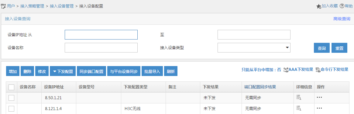
4. Click Add.
The Add Access Device page opens.
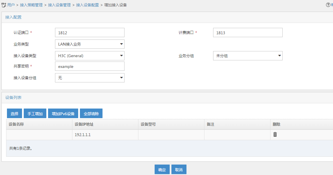
5. Configure access device parameters, as shown in Figure 3:
a. In the Shared Key field, enter example.
b. Use the default settings of other parameters in the Access Configuration area.
c. In the Device List area, manually add an access device with the IP address of 192.1.1.1. (Details not shown.)
d. Click OK.
Figure 3 Adding an access device
Configuring a security policy
1. Click the User tab.
2. From the navigation tree, select User Security Policy > Security Policy.
The security policy page opens, as shown in Figure 4.
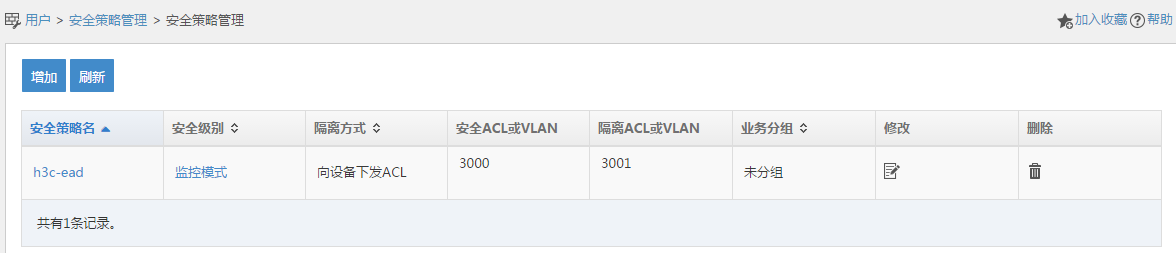
3. Click Add.
The Add Security Policy page opens.
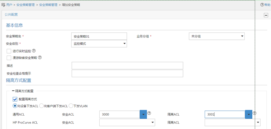
4. Configure security policy parameters, as shown in Figure 5:
a. In the Policy Name field, enter security policy 01.
b. Select Monitor from the Security Level list.
c. Select Configure Isolate Mode.
d. Select Deploy ACLs to Access Device.
e. Configure 3000 and 3001 for the Security ACL and Isolation ACL fields, respectively.
f. Use the default settings of other parameters.
g. Click OK.
Figure 5 Adding an security policy
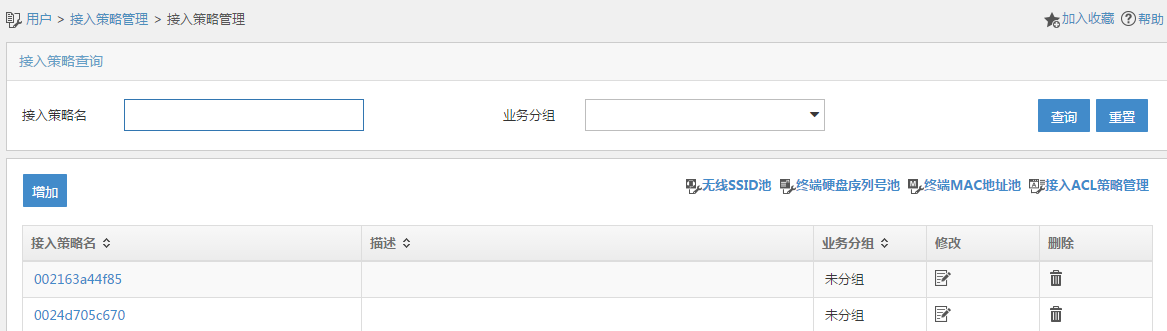
Configuring an access policy
1. Click the User tab.
2. From the navigation tree, select User Access Policy > Access Policy.
The Access Policy page opens, as shown in Figure 6.
3. Click Add.
The Add Access Policy page opens.
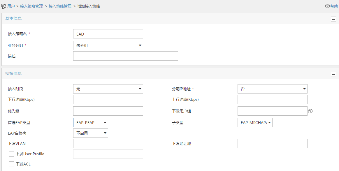
4. Configure access policy parameters, as shown in Figure 7:
a. In the Access Policy Name field, enter EAD.
b. Select EAP for the Certificate Authentication field.
c. Select EAP-PEAP Auth from the Certificate Type list, and select MS-CHAPV2 Auth from the Certificate Sub-Type list.
d. Use the default settings of other parameters.
Figure 7 Adding an access policy
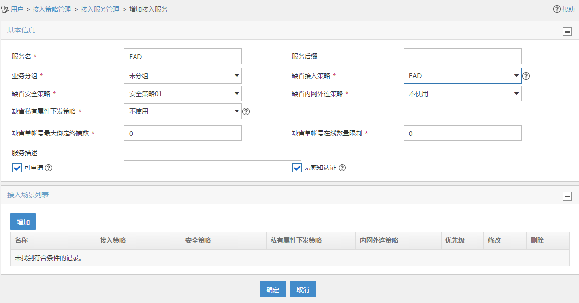
Adding an access service
1. Click the User tab.
2. From the navigation tree, select User Access Policy > Access Service.
3. Click Add.
The Add Access Service page opens.
4. configure access service parameters, as shown in Figure 8:
a. Enter EAD in the Service Name field.
b. Select security policy 01 from the Default Security Policy list.
c. Select EAD from the Default Access Policy list.
d. Use the default settings of other parameters.
e. Click OK.
Figure 8 Adding an access service
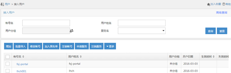
Adding an access user account
1. Click the User tab.
2. From the navigation tree, select Access User > All Access Users.
The Access User page opens, as shown in 错误!未找到引用源。.
Figure 9 Access User page
3. Click Add.
The Add Access User page opens.
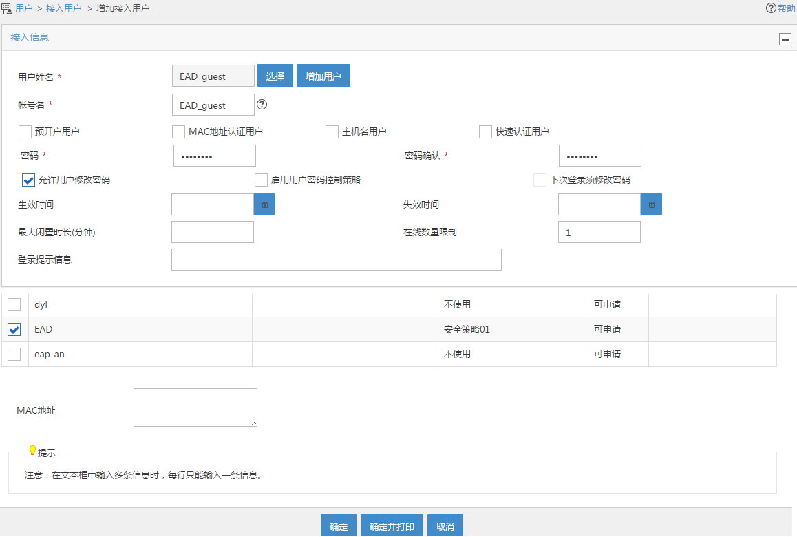
4. Configure access user parameters, as shown in Figure 10:
a. Click Add User next to the User Name field. On the Add User page that opens, enter EAD_guest in the User Name field, enter an ID number in the ID Number field, and then click OK, as shown in Figure 11.
b. Enter EAD_guest in the Account Name field.
c. Enter 12345678 in the Password and Confirm Password fields.
d. In the access service list, select EAD.
e. Use the default settings of other parameters.
f. Click OK.
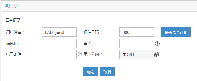
Figure 11 Adding an access user account
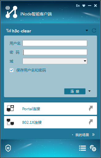
Configuring the iNode client
1. Run the iNode client, as shown in 错误!未找到引用源。.
Figure 12 iNode Client

2. Click Wireless connection.
The wireless connection page opens, as shown in 错误!未找到引用源。.
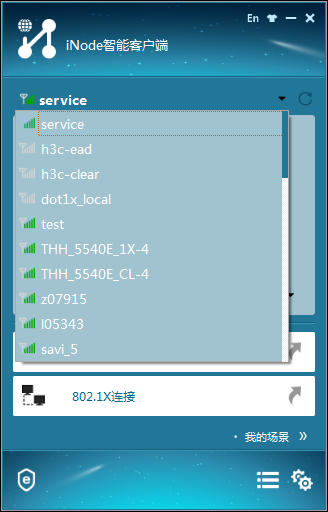
Figure 13 Wireless connection
3. Click the inverted triangle icon at the upper right corner of the page, and select the wireless service with the SSID of service, as shown in 错误!未找到引用源。.
Figure 14 Selecting an wireless service
4. Click the inverted triangle icon next to Connect and select Properties.
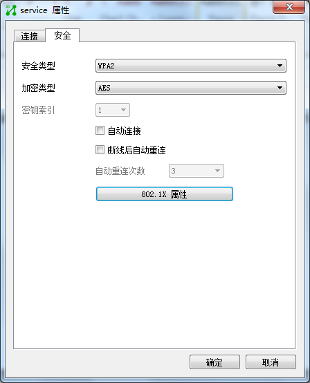
5. In the service Properties dialog box that opens, click the Security tab. Select WAP2 and AES from the Security Type and Encryption Type lists, respectively, and then click 802.1X Properties, as shown in 错误!未找到引用源。.
Figure 15 Service properties
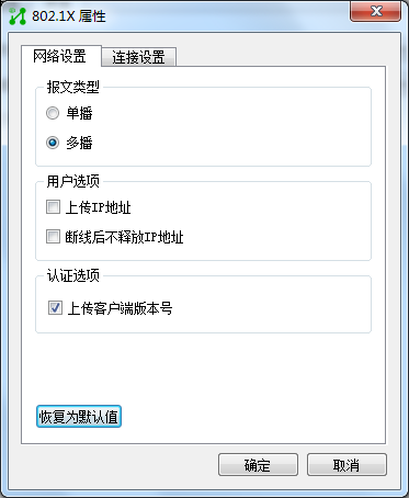
6. In the 802.1X Properties dialog box that opens, select Multicast in the Packet Type field and use the default settings of other parameters, as shown in 错误!未找到引用源。.
Figure 16 Configuring network settings of 802.1X properties
7. Click the Connect Settings tab, select PEAP for the Authentication Type field. Use the default settings of other parameters, and then click OK, as shown in 错误!未找到引用源。.
Figure 17 Configuring connection settings of 802.1X properties

8. In the 802.1X Properties dialog box, click OK.
9. On the wireless connection page, enter EAD_guest in the Username field and 12345678 in the Password field, as shown in 错误!未找到引用源。.
Figure 18 Configuring wireless connection

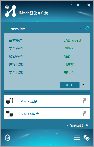
10. Click Connect.
After the connection is established, the iNode client displays the security type and encryption type, as shown in 错误!未找到引用源。.
Figure 19 Wireless connection status
Verifying the configuration
# Use the display dot1x sessions command to display 802.1x session information.
<AC> display dot1x sessions
AP name: officeap Radio ID: 2 SSID: service
Online 802.1X users: 1
MAC address Auth state
0015-00bf-e84d Authenticated
The output shows that the 802.1X user has come online.
# Use the display wlan client verbose command to display detailed WLAN client information.
<AC> display wlan client verbose
Total number of clients: 1
MAC address : 0015-00bf-e84d
IPv4 address : 192.2.1.3
IPv6 address : N/A
Username : ead_guest
AID : 1
AP ID : 2
AP name : officeap
Radio ID : 2
SSID : service
BSSID : 3891-d58a-8930
VLAN ID : 200
Sleep count : 18
Wireless mode : 802.11ac
Channel bandwidth : 80MHz
SM power save : Disabled
Short GI for 20MHz : Supported
Short GI for 40MHz : Supported
Short GI for 80MHz : Supported
Short GI for 160/80+80MHz : Not supported
STBC RX capability : Supported
STBC TX capability : Not supported
LDPC RX capability : Not supported
SU beamformee capability : Not supported
MU beamformee capability : Not supported
Beamformee STS capability : N/A
Block Ack : TID 0 Out
Supported VHT-MCS set : NSS1 0, 1, 2, 3, 4, 5, 6, 7, 8, 9
NSS2 0, 1, 2, 3, 4, 5, 6, 7, 8, 9
Supported HT MCS set : 0, 1, 2, 3, 4, 5, 6, 7,
8, 9, 10, 11, 12, 13, 14,
15
Supported rates : 6, 9, 12, 18, 24, 36,
48, 54 Mbps
QoS mode : WMM
Listen interval : 250
RSSI : 34
Rx/Tx rate : 58.5/324
Authentication method : Open system
Security mode : RSN
AKM mode : 802.1X
Cipher suite : CCMP
User authentication mode : 802.1X
Authorization ACL ID : 3000
Authorization user profile : N/A
Roam status : N/A
Key derivation : SHA1
PMF status : N/A
Forwarding policy name : N/A
Online time : 0days 0hours 2minutes 49seconds
FT status : Inactive
The output shows that ACL 3000 has been deployed, which means the EAD security policy has been deployed.
Configuration files
· AC:
#
dot1x authentication-method eap
#
port-security enable
#
vlan 100
#
vlan 200
#
wlan service-template 1
ssid service
vlan 200
akm mode dot1x
cipher-suite ccmp
security-ie rsn
client-security authentication-mode dot1x
dot1x domain radius1
service-template enable
#
interface Vlan-interface100
ip address 192.1.1.1 255.255.0.0
#
interface Vlan-interface200
ip address 192.2.1.1 255.255.255.0
#
interface GigabitEthernet1/0/1
port link-type trunk
undo port trunk permit vlan 1
port trunk permit vlan 100 200
port trunk pvid vlan 100
#
ip route-static 8.0.0.0 8 192.2.1.2
#
acl advanced 3000
rule 0 permit ip
#
acl advanced 3001
rule 0 permit udp
rule 5 deny tcp
#
radius scheme radius1
primary authentication 8.1.1.16
primary accounting 8.1.1.16
key authentication cipher $c$3$YCjREST8/BuXrsEKyY9nY8QQfmrN3w==
key accounting cipher $c$3$yPGJYnF7FE+/36JrXfn+DYGq/8ngZA==
timer realtime-accounting 3
nas-ip 192.1.1.1
#
domain radius1
authentication lan-access radius-scheme radius1
authorization lan-access radius-scheme radius1
accounting lan-access radius-scheme radius1
#
wlan ap officeap model WA4320i-ACN
serial-id 210235A1K6C15A003025
radio2
radio enable
service-template 1
#
· Switch:
#
dhcp enable
#
vlan8
#
vlan 100
#
vlan 200
#
dhcp server ip-pool vlan100
gateway-list 192.1.1.2
network 192.1.0.0 mask 255.255.0.0
forbidden-ip 192.1.1.1
#
dhcp server ip-pool vlan200
gateway-list 192.2.1.2
network 192.2.1.0 mask 255.255.255.0
forbidden-ip 192.2.1.1
#
interface Vlan-interface8
ip address 8.1.1.2 255.0.0.0
#
interface Vlan-interface100
ip address 192.1.1.2 255.255.255.0
#
interface Vlan-interface200
ip address 192.2.1.2 255.255.255.0
#
interface GigabitEthernet1/0/1
port link-type trunk
undo port trunk permit vlan 1
port trunk permit vlan 100 200
port trunk pvid vlan 100
#
interface GigabitEthernet1/0/2
port link-type trunk
undo port trunk permit vlan 1
port trunk permit vlan 100 200
port trunk pvid vlan 100
poe enable
#
interface GigabitEthernet1/0/3
port link-type trunk
undo port trunk permit vlan 1
port trunk permit vlan 100 200
port trunk pvid vlan 8
#
Related documentation
· Security Command Reference in H3C Access Controllers Command References
· Security Configuration Guide in H3C Access Controllers Configuration Guides
· WLAN Command Reference in H3C Access Controllers Command References
· WLAN Configuration Guide in H3C Access Controllers Configuration Guides
