- Table of Contents
-
- H3C Access Controllers and Access Points Configuration Examples(V7)-6W101
- 00-Preface
- 01-H3C Access Controllers AP's Association with the AC at Layer 2 Configuration Examples
- 02-H3C Access Controllers Comware 7 AP's Association with the AC at Layer 2 (IPv6) Configuration Examples
- 03-H3C Access Controllers AP's Association with the AC at Layer 3 Configuration Examples
- 04-H3C Access Controllers Comware 7 AP's Association with the AC at Layer 3 (IPv6) Configuration Examples
- 05-H3C Access Controllers Local MAC Authentication Configuration Examples (V7)
- 06-H3C Access Controllers MAC Authentication with Guest VLAN Assignment Configuration Examples (V7)
- 07-H3C Access Controllers Comware 7 MAC Authentication with Guest VLAN Assignment (IPv6) Configuration Examples
- 08-H3C Access Controllers MAC Authentication and PSK Authentication Configuration Examples (V7)
- 09-H3C Access Controllers Auto AP Configuration Examples (V7)
- 10-H3C Access Controllers WLAN Load Balancing Configuration Examples (V7)
- 11-H3C Access Controllers WEP Encryption Configuration Examples
- 12-H3C Access Controllers Local Forwarding Configuration Examples
- 13-H3C Access Controllers Layer 2 Static Aggregation Configuration Examples (V7)
- 14-H3C Access Controllers Remote 802.1X Authentication Configuration Examples (V7)
- 15-H3C Access Controllers Comware 7 Remote 802.1X Authentication (IPv6) Configuration Examples
- 16-H3C Access Controllers 802.1X Authentication with ACL Assignment Through IMC Server @CE@ (V7)
- 17-H3C Access Controllers 802.1X Authentication with User Profile Assignment Through IMC Server @CE@ (V7)
- 18-H3C Access Controllers EAD Authentication Configuration Examples (V7)
- 19-H3C Access Controllers Comware 7 EAD Authentication (IPv6) Configuration Examples
- 20-H3C Access Controllers Remote Portal Authenticaiton Configuration Examples (V7)
- 21-H3C Access Controllers Comware 7 Remote Portal Authenticaiton (IPv6) Configuration Examples
- 22-H3C Access Controllers Local Portal Authentication Configuration Examples (V7)
- 23-H3C Access Controllers Comware 7 Local Portal Authentication (IPv6) Configuration Examples
- 24-H3C Access Controllers Local Forwarding Mode Direct Portal Authentication Configuration Examples (V7)
- 25-H3C Access Controllers Local Forwarding Mode Direct Portal Authentication (IPv6) Configuration Examples(V7)
- 26-H3C Access Controllers Local Portal Authentication through LDAP Server Configuration Examples (V7)
- 27-H3C Access Controllers Local Portal Authentication through LDAP Server (IPv6) Configuration Examples(V7)
- 28-H3C Access Controllers MAC-based Portal Quick Authenticaiton Configuration Example (V7)
- 29-H3C Access Controllers Comware 7 MAC-based Quick Portal Authenticaiton (IPv6) Configuration Example
- 30-H3C Access Controllers SSH Configuration Examples (7)
- 31-H3C Access Controllers Internal-to-External Access Through NAT Configuration Examples (V7)
- 32-H3C Access Controllers Static Blacklist Configuration Examples
- 33-H3C Access Controllers Comware 7 WLAN Access (IPv6) Configuration Examples
- 34-H3C Access Controllers Inter-AC Roaming Configuration Examples (V7)
- 35-H3C Access Controllers Comware 7 Inter-AC Roaming (IPv6) Configuration Examples
- 36-H3C Access Controllers HTTPS Login Configuration Examples (V7)
- 37-H3C Access Controllers Client Rate Limiting Configuration Examples (V7)
- 38-H3C Access Controllers Client Quantity Control Configuration Examples
- 39-H3C Access Controllers Medical RFID Tag Management Configuration Examples (V7)
- 40-H3C Access Controllers iBeacon Management Configuration Examples (V7)
- 41-H3C Access Controllers Remote AP Configuration Examples (V7)
- 42-H3C Access Controllers PSK Encryption Configuration Examples
- 43-H3C Access Controllers WIPS Configuration Examples (V7)
- 44-H3C Access Controllers Layer 2 Multicast Configuration Example (V7)
- 45-H3C Access Controllers IRF Setup with Members Directly Connected Configuration Examples (V7)
- 46-H3C Access Controllers IRF Setup with Members Not Directly Connected Configuration Examples (V7)
- 47-H3C Access Controller Modules IRF Setup with Members in One Chassis Configuration Examples (V7)
- 48-H3C Access Controller Modules IRF Setup with Members in Different Chassis Configuration Examples (V7)
- 49-H3C Access Controllers Comware 7 IP Source Guard (IPv6) Configuration Examples
- 50-Policy-Based Forwarding with Dual Gateways Configuration Example
- 51-H3C Access Controllers Comware 7 Policy-Based Forwarding with Dual Gateways (IPv6) Configuration Example
- 52-Policy-Based Local Forwarding Configuration Examples
- Related Documents
-
| Title | Size | Download |
|---|---|---|
| 13-H3C Access Controllers Layer 2 Static Aggregation Configuration Examples (V7) | 53.46 KB |
|
|
|
H3C Access Controllers |
|
Comware 7 Layer 2 Static Aggregation |
|
Configuration Examples |
Copyright © 2019 New H3C Technologies Co., Ltd. All rights reserved.
No part of this manual may be reproduced or transmitted in any form or by any means without prior written consent of New H3C Technologies Co., Ltd.
Except for the trademarks of New H3C Technologies Co., Ltd., any trademarks that may be mentioned in this document are the property of their respective owners.
The information in this document is subject to change without notice.
Introduction
This document provides Layer 2 static aggregation configuration examples.
Prerequisites
This document applies to Comware 7-based access controllers and access points. Procedures and information in the examples might be slightly different depending on the software or hardware version of the access controllers and access points.
The configuration examples in this document were created and verified in a lab environment, and all the devices were started with the factory default configuration. When you are working on a live network, make sure you understand the potential impact of every command on your network.
This document assumes that you have basic knowledge of H3C Ethernet link aggregation.
Example: Configuring a Layer 2 static aggregation group
Network configuration
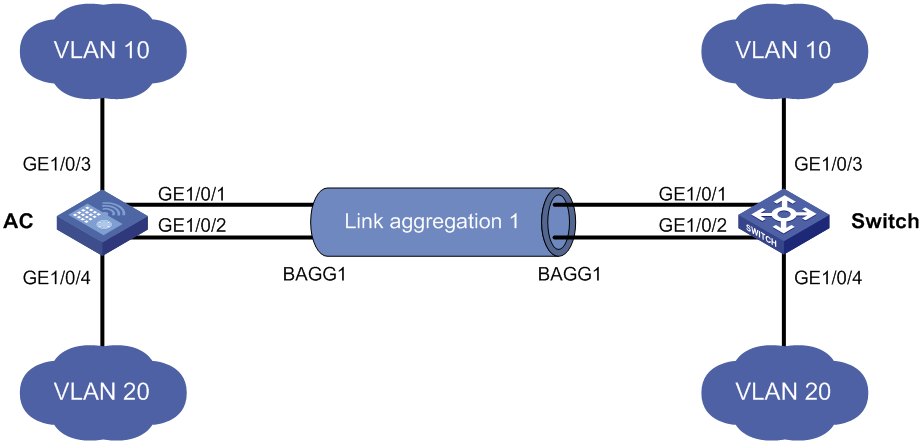
On the network shown in Figure 1, perform the following tasks:
· Configure a Layer 2 static aggregation group on the AC and the switch to increase the bandwidth and improve link reliability.
· Enable VLAN 10 at one end of the aggregate link to communicate with VLAN 10 at the other end.
· Enable VLAN 20 at one end of the aggregate link to communicate with VLAN 20 at the other end.
Procedures
Configuring the AC
1. Configure VLANs:
# Create VLAN 10, and assign port GigabitEthernet 1/0/3 to VLAN 10.
<AC> system-view
[AC] vlan 10
[AC-vlan10] port gigabitethernet 1/0/3
[AC-vlan10] quit
# Create VLAN 20, and assign port GigabitEthernet 1/0/4 to VLAN 20.
[AC] vlan 20
[AC-vlan20] port gigabitethernet 1/0/4
[AC-vlan20] quit
2. Configure a Layer 2 aggregate interface:
# Create Layer 2 aggregate interface Bridge-Aggregation 1.
[AC] interface bridge-aggregation 1
[AC-Bridge-Aggregation1] quit
# Assign port GigabitEthernet 1/0/1 to link aggregation group 1.
[AC] interface gigabitethernet 1/0/1
[AC-GigabitEthernet1/0/1] port link-aggregation group 1
[AC-GigabitEthernet1/0/1] quit
# Assign port GigabitEthernet 1/0/2 to link aggregation group 1.
[AC] interface gigabitethernet1/0/2
[AC-GigabitEthernet1/0/2] port link-aggregation group 1
[AC-GigabitEthernet1/0/2] quit
# Configure Layer 2 aggregate interface Bridge-Aggregation 1 as a trunk port and assign it to VLANs 10 and 20.
[AC] interface bridge-aggregation 1
[AC-Bridge-Aggregation1] port link-type trunk
[AC-Bridge-Aggregation1] port trunk permit vlan 10 20
[AC-Bridge-Aggregation1] quit
Configuring the switch
1. Configure VLANs:
# Create VLAN 10, and assign port GigabitEthernet 1/0/3 to VLAN 10.
<Switch> system-view
[Switch] vlan 10
[Switch-vlan10] port gigabitethernet 1/0/3
[Switch-vlan10] quit
# Create VLAN 20, and assign port GigabitEthernet 1/0/4 to VLAN 20.
[Switch] vlan 20
[Switch-vlan20] port gigabitethernet 1/0/4
[Switch-vlan20] quit
2. Configure a Layer 2 aggregate interface:
# Create Layer 2 aggregate interface Bridge-Aggregation 1.
[Switch] interface bridge-aggregation 1
[Switch-Bridge-Aggregation1] quit
# Assign port GigabitEthernet 1/0/1 to link aggregation group 1.
[Switch] interface gigabitethernet 1/0/1
[Switch-GigabitEthernet1/0/1] port link-aggregation group 1
[Switch-GigabitEthernet1/0/1] quit
# Assign port GigabitEthernet 1/0/2 to link aggregation group 1.
[Switch] interface gigabitethernet 1/0/2
[Switch-GigabitEthernet1/0/2] port link-aggregation group 1
[Switch-GigabitEthernet1/0/2] quit
# Configure Layer 2 aggregate interface Bridge-Aggregation 1 as a trunk port and assign it to VLANs 10 and 20.
[Switch] interface bridge-aggregation 1
[Switch-Bridge-Aggregation1] port link-type trunk
[Switch-Bridge-Aggregation1] port trunk permit vlan 10 20
[Switch-Bridge-Aggregation1] quit
Verifying the configuration
1. Verify that GigabitEthernet 1/0/1 and GigabitEthernet 1/0/2 on the AC are Selected ports in Layer 2 static aggregation group 1.
<AC> display link-aggregation verbose
Loadsharing Type: Shar -- Loadsharing, NonS -- Non-Loadsharing
Port Status: S -- Selected, U -- Unselected, I -- Individual
Flags: A -- LACP_Activity, B -- LACP_Timeout, C -- Aggregation,
D -- Synchronization, E -- Collecting, F -- Distributing,
G -- Defaulted, H -- Expired
Aggregate Interface: Bridge-Aggregation1
Aggregation Mode: Static
Loadsharing Type: Shar
System ID: 0x8000, 000f-e267-6c6a
Local:
Port Status Priority Oper-Key Flag
--------------------------------------------------------------------------------
GE1/0/1 S 32768 2 {ACDEF}
GE1/0/2 S 32768 2 {ACDEF}
Remote:
Actor Partner Priority Oper-Key SystemID Flag
--------------------------------------------------------------------------------
GE1/0/1 1 32768 2 0x8000, 000f-e267-57ad {ACDEF}
GE1/0/2 1 32768 2 0x8000, 000f-e267-57ad {ACDEF}
GE1/0/3 1 32768 2 0x8000, 0000-0000-0000 {DEF}
2. Verify that the bandwidth for Layer 2 aggregate interface Bridge-Aggregation 1 is the total bandwidth of GigabitEthernet 1/0/1 and GigabitEthernet 1/0/2 on the AC.
<AC> display interface bridge-aggregation 1
Bridge-Aggregation1
Current state: UP
IP packet frame type: Ethernet II, hardware address: 741f-4a05-3db8
Description: Bridge-Aggregation1 Interface
Bandwidth: 2000000 kbps
2Gbps-speed mode, full-duplex mode
Link speed type is autonegotiation, link duplex type is autonegotiation
PVID: 1
Port link-type: Trunk
VLAN Passing: 1(default vlan), 10
VLAN permitted: 1(default vlan), 10, 20
Trunk port encapsulation: IEEE 802.1q
Last clearing of counters: Never
Last 300 seconds input: 2 packets/sec 308 bytes/sec 0%
Last 300 seconds output: 0 packets/sec 0 bytes/sec 0%
Input (total): 12659 packets, 1290752 bytes
177 unicasts, 9919 broadcasts, 2563 multicasts, 0 pauses
Input (normal): 12659 packets, - bytes
177 unicasts, 9919 broadcasts, 2563 multicasts, 0 pauses
Input: 0 input errors, 0 runts, 0 giants, - throttles
0 CRC, - frame, 0 overruns, 0 aborts
- ignored, - parity errors
Output (total): 316 packets, 295765 bytes
307 unicasts, 9 broadcasts, 0 multicasts, 0 pauses
Output (normal): 316 packets, - bytes
307 unicasts, 9 broadcasts, 0 multicasts, 0 pauses
Output: 0 output errors, 0 underruns, - buffer failures
0 aborts, 0 deferred, 0 collisions, 0 late collisions
- lost carrier, - no carrier
Configuration files
· AC:
#
vlan 10
#
vlan20
#
interface Bridge-Aggregation1
port link-type trunk
port trunk permit vlan 1 10 20
#
interface GigabitEthernet1/0/1
port link-type trunk
port trunk permit vlan 1 10 20
port link-aggregation group 1
#
interface GigabitEthernet1/0/2
port link-type trunk
port trunk permit vlan 1 10 20
port link-aggregation group 1
#
· Switch:
#
vlan 10
#
vlan 20
#
interface Bridge-Aggregation1
port link-type trunk
port trunk permit vlan 1 10 20
#
interface GigabitEthernet1/0/1
port link-type trunk
port trunk permit vlan 1 10 20
port link-aggregation group 1
#
interface GigabitEthernet1/0/2
port link-type trunk
port trunk permit vlan 1 10 20
port link-aggregation group 1
#
Related documentation
· Layer 2—LAN Switching Command Reference in H3C Access Controllers Command References
· Layer 2—LAN Switching Configuration Guide in H3C Access Controllers Configuration Guides
