- Table of Contents
-
- H3C S12500R Ethernet Switch Router Series Config Examples-Release 36xx-6W100
- 01-Login Management Configuration Examples
- 02-RBAC Configuration Examples
- 03-Software Upgrade Examples
- 04-Ethernet Link Aggregation Configuration Examples
- 05-Port Isolation Configuration Examples
- 06-Spanning Tree Configuration Examples
- 07-VLAN Configuration Examples
- 08-VLAN Tagging Configuration Examples
- 09-DHCP Snooping Configuration Examples
- 10-Cross-Subnet Dynamic IP Address Allocation Configuration Examples
- 11-IPv6 over IPv4 Tunneling with OSPFv3 Configuration Examples
- 12-GRE Tunnel Configuration Examples
- 13-GRE with OSPF Configuration Examples
- 14-OSPF Configuration Examples
- 15-IS-IS Configuration Examples
- 16-BGP Configuration Examples
- 17-Policy-Based Routing Configuration Examples
- 18-OSPFv3 Configuration Examples
- 19-IPv6 IS-IS Configuration Examples
- 20-Routing Policy Configuration Examples
- 21-IGMP Snooping Configuration Examples
- 22-IGMP Configuration Examples
- 23-MLD Snooping Configuration Examples
- 24-Basic MPLS Configuration Examples
- 25-MPLS L3VPN Configuration Examples
- 26-ACL Configuration Examples
- 27-Control Plane-Based QoS Policy Configuration Examples
- 28-Traffic Policing Configuration Examples
- 29-GTS and Rate Limiting Configuration Examples
- 30-Priority Mapping and Queue Scheduling Configuration Examples
- 31-Traffic Filtering Configuration Examples
- 32-AAA Configuration Examples
- 33-SSH Configuration Examples
- 34-IP Source Guard Configuration Examples
- 35-Ethernet OAM Configuration Examples
- 36-CFD Configuration Examples
- 37-DLDP Configuration Examples
- 38-VRRP Configuration Examples
- 39-BFD Configuration Examples
- 40-NTP Configuration Examples
- 41-SNMP Configuration Examples
- 42-NQA Configuration Examples
- 43-Mirroring Configuration Examples
- 44-sFlow Configuration Examples
- 45-OpenFlow Configuration Examples
- 46-MAC Address Table Configuration Examples
- 47-Static Multicast MAC Address Entry Configuration Examples
- 48-IP Unnumbered Configuration Examples
- 49-Congestion Avoidance and Queue Scheduling Configuration Examples
- 50-Attack Protection Configuration Examples
- 51-Smart Link Configuration Examples
- 52-RRPP Configuration Examples
- 53-BGP Route Selection Configuration Examples
- 54-IS-IS Route Summarization Configuration Examples
- 55-MPLS OAM Configuration Examples
- 56-MPLS TE Configuration Examples
- 57-VXLAN Configuration Examples
- 58-NetStream Configuration Examples
- 59-EVPN-DCI over an MPLS L3VPN Network Configuration Examples
- 60-PTP Configuration Examples
- 61-S-MLAG Configuration Examples
- 62-MPLS SR Configuration Examples
- 63-Puppet Configuration Examples
- Related Documents
-
| Title | Size | Download |
|---|---|---|
| 07-VLAN Configuration Examples | 90.99 KB |
|
|
|
H3C S12500R Switch Router Series |
|
VLAN Configuration Examples |
|
|
Copyright © 2021 New H3C Technologies Co., Ltd. All rights reserved.
No part of this manual may be reproduced or transmitted in any form or by any means without prior written consent of New H3C Technologies Co., Ltd.
Except for the trademarks of New H3C Technologies Co., Ltd., any trademarks that may be mentioned in this document are the property of their respective owners.
The information in this document is subject to change without notice.
Contents
Example: Configuring port-based VLANs
Example: Configuring the super VLAN
Configuration restrictions and guidelines
Introduction
This document provides examples of configuring the port-based VLAN and super VLAN.
Prerequisites
The configuration examples in this document were created and verified in a lab environment, and all the devices were started with the factory default configuration. When you are working on a live network, make sure you understand the potential impact of every command on your network.
This document assumes that you have basic knowledge of VLANs.
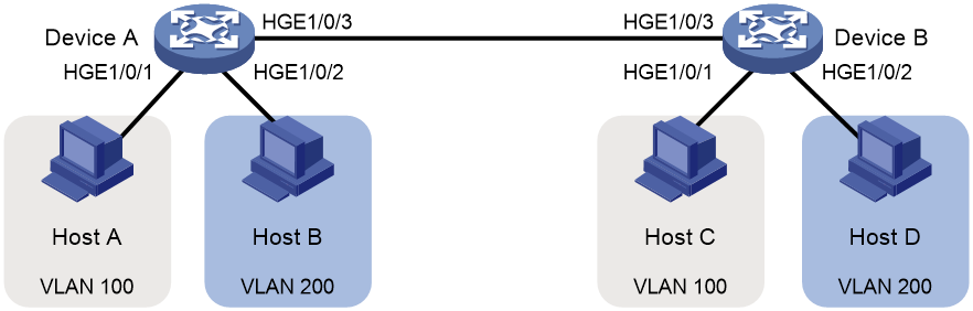
Example: Configuring port-based VLANs
Network configuration
As shown in Figure 1:
· Host A and Host C belong to Department A. VLAN 100 is assigned to Department A.
· Host B and Host D belong to Department B. VLAN 200 is assigned to Department B.
Configure port-based VLANs so that hosts only in the same department can communicate with each other.
Software versions used
This configuration example was created and verified on R3606.
Restrictions and guidelines
By default, interfaces on the device are disabled (in ADM or Administratively Down state). To have an interface operate, you must use the undo shutdown command to enable that interface.
Procedures
# Configure HundredGigE 1/0/1 and HundredGigE 1/0/3 to operate in bridge mode.
[DeviceA] interface range hundredgige1/0/1 to hundredgige1/0/3
[DeviceA-if-Range] port link-mode bridge
[DeviceA-if-Range] quit
# Create VLAN 100, and assign HundredGigE 1/0/1 to VLAN 100.
[DeviceA-vlan100] port hundredgige 1/0/1
[DeviceA-vlan100] quit
# Create VLAN 200, and assign HundredGigE 1/0/2 to VLAN 200.
[DeviceA-vlan200] port hundredgige 1/0/2
[DeviceA-vlan200] quit
# Configure HundredGigE 1/0/3 as a trunk port, and assign it to VLANs 100 and 200.
[DeviceA] interface hundredgige 1/0/3
[DeviceA-HundredGigE1/0/3] port link-type trunk
[DeviceA-HundredGigE1/0/3] port trunk permit vlan 100 200
2. Configure Device B in the same way Device A is configured. (Details not shown.)
3. Configure hosts:
a. Configure Host A and Host C to be on the same IP subnet. For example, 192.168.100.0/24.
b. Configure Host B and Host D to be on the same IP subnet. For example, 192.168.200.0/24.
Verifying the configuration
# Verify that Host B and Host D can ping each other, but they both fail to ping Host A or Host C. (Details not shown.)
# Display information about VLANs 100 and 200 on Device A.
[DeviceA-HundredGigE1/0/3] display vlan 100
VLAN ID: 100
VLAN type: Static
Route interface: Not configured
Description: VLAN 0100
Name: VLAN 0100
Tagged ports:
HundredGigE1/0/3
Untagged ports:
HundredGigE1/0/1
[DeviceA-HundredGigE1/0/3] display vlan 200
VLAN ID: 200
VLAN type: Static
Route interface: Not configured
Description: VLAN 0200
Name: VLAN 0200
Tagged ports:
HundredGigE1/0/3
Untagged ports:
HundredGigE1/0/2
The output shows that:
· HundredGigE 1/0/3 and HundredGigE 1/0/1 permit packets from 100 to pass through.
· HundredGigE 1/0/3 and HundredGigE 1/0/2 permit packets from 200 to pass through.
Configuration files
Configuration files on both Device B and Device A are the same. The following configuration files use Device A as an example.
#
vlan 100
#
vlan 200
#
interface HundredGigE1/0/1
port link-mode bridge
port access vlan 100
#
interface HundredGigE1/0/2
port link-mode bridge
port access vlan 200
#
interface HundredGigE1/0/3
port link-mode bridge
port link-type trunk
port trunk permit vlan 1 100 200
#
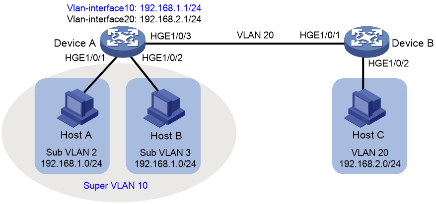
Example: Configuring the super VLAN
Network configuration
As shown in Figure 2:
· Users in VLAN 2 access the network through HundredGigE 1/0/1 of Device A.
· Users in VLAN 3 access the network through HundredGigE 1/0/2 of Device A.
· HundredGigE 1/0/3 of Device A and HundredGigE 1/0/1 of Device B are in VLAN 20.
· Users in VLAN 20 use the gateway address 192.168.2.1 and IP addresses on the IP network segment 192.168.2.0/24.
Configure a super VLAN to meet the following requirements:
· Users in VLAN 2 and VLAN 3 use the gateway address 192.168.1.1 and IP addresses on the IP network segment 192.168.1.0/24.
· Users in VLAN 2, VLAN 3, and VLAN 20 are isolated at Layer 2 but interoperable at Layer 3.
Software versions used
This configuration example was created and verified on R3606.
Configuration restrictions and guidelines
A super VLAN does not have physical ports. A VLAN that has physical ports cannot be configured as a super VLAN.
By default, interfaces on the device are disabled (in ADM or Administratively Down state). To have an interface operate, you must use the undo shutdown command to enable that interface.
Procedures
Configuring Device A
# Create VLAN 10 and configure it as a super VLAN.
<DeviceA> system-view
[DeviceA] vlan 10
[DeviceA-vlan10] supervlan
[DeviceA-vlan10] quit
# Configure HundredGigE 1/0/1 and HundredGigE 1/0/3 to operate in bridge mode.
[DeviceA] interface range Hundredgige1/0/1 to Hundredgige1/0/3
[DeviceA-if-Range] port link-mode bridge
[DeviceA-if-Range] quit
# Create VLAN 2, and assign HundredGigE 1/0/1 to VLAN 2.
[DeviceA] vlan 2
[DeviceA-vlan2] port hundredgige 1/0/1
[DeviceA-vlan2] quit
# Create VLAN 3, and assign HundredGigE 1/0/2 to VLAN 3.
[DeviceA] vlan 3
[DeviceA-vlan3] port hundredgige 1/0/2
[DeviceA-vlan3] quit
# Associate super VLAN 10 with VLANs 2 and 3.
[DeviceA] vlan 10
[DeviceA-vlan10] subvlan 2 3
[DeviceA-vlan10] quit
# Create VLAN-interface 10, and assign IP address 192.168.1.1 to it.
[DeviceA] interface vlan-interface 10
[DeviceA-Vlan-interface10] ip address 192.168.1.1 24
# Enable local proxy ARP on VLAN-interface 10.
[DeviceA-Vlan-interface10] local-proxy-arp enable
[DeviceA-Vlan-interface10] quit
# Create VLAN 20.
[DeviceA] vlan 20
[DeviceA-vlan20] quit
# Configure HundredGigE 1/0/3 as a trunk port, and remove the port from VLAN 1.
[DeviceA] interface hundredgige 1/0/3
[DeviceA-HundredGigE1/0/3] port link-type trunk
[DeviceA-HundredGigE1/0/3] undo port trunk permit vlan 1
# Assign HundredGigE 1/0/3 to VLAN 20.
[DeviceA-HundredGigE1/0/3] port trunk permit vlan 20
# Create VLAN-interface 20, and assign IP address 192.168.2.1 to it.
[DeviceA] interface Vlan-interface 20
[DeviceA-Vlan-interface20] ip address 192.168.2.1 24
[DeviceA-Vlan-interface20] quit
Configuring Device B
# Create VLAN 20.
[DeviceB] vlan 20
[DeviceB-vlan20] quit
# Configure HundredGigE 1/0/1 to operate in bridge mode.
[DeviceB] interface Hundredgige1/0/1
[DeviceB-Hundredgige1/0/1] port link-mode bridge
[DeviceB-Hundredgige1/0/1] quit
# Configure HundredGigE 1/0/1 as a trunk port, and remove the port from VLAN 1.
[DeviceB] interface hundredgige 1/0/1
[DeviceB-HundredGigE1/0/1] port link-type trunk
[DeviceB-HundredGigE1/0/1] undo port trunk permit vlan 1
# Assign HundredGigE 1/0/1 to VLAN 20.
[DeviceB-HundredGigE1/0/1] port trunk permit vlan 20
# Assign HundredGigE 1/0/2 to VLAN 20.
[DeviceB] vlan 20
[DeviceB-vlan20] port hundredgige 1/0/2
[DeviceB-vlan20] quit
Verifying the configuration
# Verify the super VLAN configuration.
[DeviceA] display supervlan
Super VLAN ID: 10
Sub-VLAN ID: 2-3
VLAN ID: 10
VLAN type: Static
It is a super VLAN.
Route interface: Configured
IPv4 address: 192.168.1.1
IPv4 subnet mask: 255.255.255.0
Description: VLAN 0010
Name: VLAN 0010
Tagged ports: none
Untagged ports: none
VLAN ID: 2
VLAN type: Static
It is a sub-VLAN.
Route interface: Configured
IPv4 address: 192.168.1.1
IPv4 subnet mask: 255.255.255.0
Description: VLAN 0002
Name: VLAN 0002
Tagged ports: none
Untagged ports:
HundredGigE1/0/1
VLAN ID: 3
VLAN type: Static
It is a sub-VLAN.
Route interface: Configured
IPv4 address: 192.168.1.1
IPv4 subnet mask: 255.255.255.0
Description: VLAN 0003
Name: VLAN 0003
Tagged ports: none
Untagged ports:
HundredGigE1/0/2
# Verify that Host A and Host B can ping each other. In the ARP table of Host A, the IP address of Host B corresponds to the MAC address of VLAN-interface 10. In the ARP table of Host B, the IP address of Host A corresponds to the MAC address of VLAN-interface 10. (Details not shown.)
# Verify that Host A and Host C can ping each other. In the ARP table of Host A, no entry about Host C exists. In the ARP table of Host C, no entry about Host A exists. (Details not shown.)
# Verify that Host B and Host C can ping each other. In the ARP table of Host B, no entry about Host C exists. In the ARP table of Host C, no entry about Host B exists. (Details not shown.)
Configuration files
· Device A:
#
vlan 2
#
vlan 3
#
vlan 10
supervlan
subvlan 2 3
#
vlan 20
#
interface Vlan-interface10
ip address 192.168.1.1 255.255.255.0
local-proxy-arp enable
#
interface Vlan-interface20
ip address 192.168.2.1 255.255.255.0
#
interface HundredGigE1/0/1
port link-mode bridge
port access vlan 2
#
interface HundredGigE1/0/2
port link-mode bridge
port access vlan 3
#
interface HundredGigE1/0/3
port link-mode bridge
port link-type trunk
undo port trunk permit vlan 1
port trunk permit vlan 20
#
· Device B:
#
vlan 20
#
interface HundredGigE1/0/1
port link-mode bridge
port link-type trunk
undo port trunk permit vlan 1
port trunk permit vlan 20
#
port link-mode bridge
port access vlan 20
#
Related documentation
· H3C S12500R Switch Router Series Layer 2—LAN Switching Command Reference-R3606
· H3C S12500R Switch Router Series Layer 2—LAN Switching Configuration Guide-R3606
