- Table of Contents
-
- 05-Web configuration examples (AC+fit AP)
- 01-Telnet Access Control Configuration Example
- 02-IPv6 Telnet Access Control Configuration Example
- 03-Web Access Control Configuration Example
- 04-User Role Assignment for Local Web Authentication Users Configuration Example
- 05-SSH Local Authentication Configuration Example
- 06-SSH User Remote Password Authentication Configuration Example
- 07-IPv6 SSH User Remote Password Authentication Configuration Example
- 08-Password Control Configuration Example
- 09-Licensing Configuration Example
- 10-Automatic License Installation Configuration Example
- 11-Layer 2 Static Link Aggregation Configuration Example
- 12-Layer 2 Dynamic Link Aggregation Configuration Example
- 13-PPPoE Client Configuration Example
- 14-Static IPv6 Address Configuration Example
- 15-IPv6 Static Routing Configuration Example
- 16-Static IPv4 DNS Configuration Example
- 17-Static IPv6 DNS Configuration Example
- 18-IGMP Snooping Configuration Example
- 19-MLD Snooping Configuration Example
- 20-IPv4 DNS Proxy Configuration Example
- 21-IPv6 DNS Proxy Configuration Example
- 22-Static NAT Configuration Example
- 23-Dynamic NAT Configuration Example
- 24-IPv4 ACL-Based Packet Filter Configuration Example
- 25-IPv6 ACL-Based Packet Filter Configuration Example
- 26-ARP Attack Protection Configuration Example
- 27-ARP Proxy Configuration Example
- 28-Dynamic IPv4 DNS Configuration Example
- 29-Dynamic IPv6 DNS Configuration Example
- 30-WLAN Access Configuration Example
- 31-Different Wireless Services on Different Radios Configuration Example
- 32-CAPWAP Tunnel Establishment Through DHCP Configuration Example
- 33-CAPWAP Tunnel Establishment Through DHCPv6 Configuration Example
- 34-CAPWAP Tunnel Establishment Through DNS Configuration Example
- 35-CAPWAP Tunnel Establishment Through DNSv6 Configuration Example
- 36-Auto AP Configuration Example
- 37-AP Group Configuration Example
- 38-Radio Management Configuration Example
- 39-Load Balancing Group-Based Session-Mode Load Balancing Configuration Example
- 40-Radio-Based Session-Mode Load Balancing Configuration Example
- 41-A-MPDU and A-MSDU Configuration Example
- 42-Device Classification and Countermeasure Configuration Example
- 43-Malformed Packet Detection and Flood Attack Detection Configuration Example
- 44-Signature-Based Attack Detection Configuration Example
- 45-802.1X RADIUS-Based AAA Configuration Example
- 46-VLAN Interface-Based Direct Portal Authentication Configuration Example
- 47-Service Template-Based Direct Portal Authentication Configuration Example
- 48-Wireless Spectrum Analysis Configuration Example
- 49-Auto DFS Configuration Examples
- 50-Auto TPC Configuration Examples
- 51-Whitelist-Based Client Access Control Configuration Example
- 52-Blacklist-Based Client Access Control Configuration Example
- 53-CAC Configuration Example
- 54-WLAN Probe Configuration Example
- 55-Intra-AC Roaming Configuration Example
- 56-Bonjour Gateway Configuration Example
- 57-IPv4 Multicast Optimization Configuration Examples
- 58-IPv6 Multicast Optimization Configuration Examples
- 59-Ping Configuration Example
- 60-Local Packet Capture Configuration Example
- 61-Remote Packet Capture Configuration Example
- Related Documents
-
| Title | Size | Download |
|---|---|---|
| 30-WLAN Access Configuration Example | 274.23 KB |
|
|
|
H3C Access Controllers |
|
WLAN Access Configuration Example |
|
|
Copyright © 2022 New H3C Technologies Co., Ltd. All rights reserved.
No part of this manual may be reproduced or transmitted in any form or by any means without prior written consent of New H3C Technologies Co., Ltd.
Except for the trademarks of New H3C Technologies Co., Ltd., any trademarks that may be mentioned in this document are the property of their respective owners.
The information in this document is subject to change without notice.
Contents
Example: Configuring WLAN access
Creating a VLAN for client access
Configuring the VLAN for client access
Overview
The following information provides an example for configuring WLAN access.
Prerequisites
The following information applies to Comware 7-based access controllers. Procedures and information in the examples might be slightly different depending on the software or hardware version of the H3C access controllers.
The configuration examples were created and verified in a lab environment, and all the devices were started with the factory default configuration. When you are working on a live network, make sure you understand the potential impact of every command on your network.
The following information is provided based on the assumption that you have basic knowledge of WLAN access.
Example: Configuring WLAN access
Network configuration
As shown in Figure 1, the AC assigns IP addresses to the AP and clients as a DHCP server. The AP provides wireless services with SSID trade-off. Configure clients accessing the WLAN to join VLAN 2.

Procedures
Creating a VLAN for client access
1. Click the System View tab at the bottom of the page.
2. From the navigation pane, select Network Configuration > VLAN.
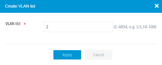
3. Click the Create VLANs button ![]() and create VLAN 2.
and create VLAN 2.
Figure 2 Creating a VLAN
4. Click the Edit icon ![]() for
VLAN 2.
for
VLAN 2.
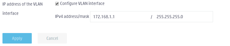
5. Select Configure VLAN interface and specify the IPv4 address/mask as 172.168.1.1/255.255.255.0.
Figure 3 Creating a VLAN interface
Configuring the DHCP service
1. From the navigation pane, select Network Configuration > Network Services > DHCP/DNS.
2. Click the Address pool button.
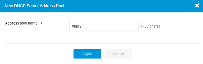
3. Click the Add Address Pool button and create VLAN pool vlan2.
Figure 4 Creating an address pool
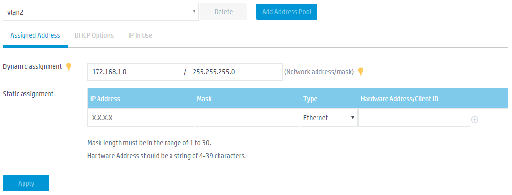
4. Specify the dynamic assignment network segment as 172.168.1.0/255.255.255.0 for address pool vlan2.
Figure 5 Specifying the dynamic assignment network segment
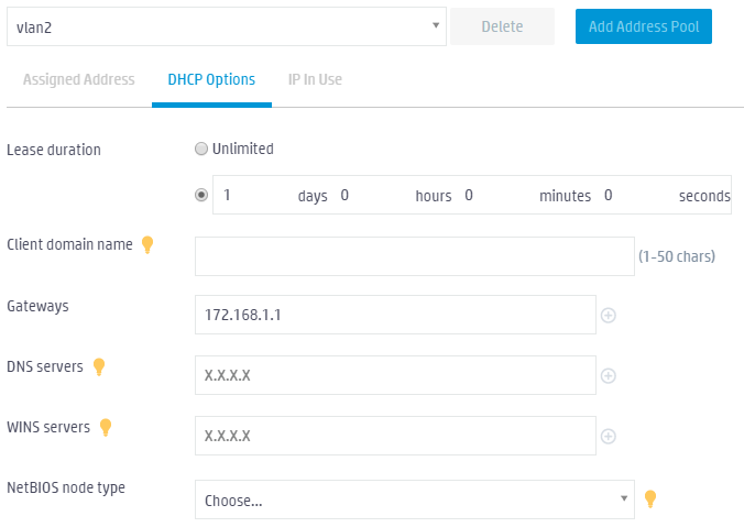
5. Click the DHCP Options tab and specify gateway address 172.168.1.1.
Figure 6 Configuring DHCP options
Configuring the VLAN for client access
1. Click the Network View tab at the bottom of the page.
2. From the navigation pane, select Wireless Configuration > Wireless Networks.
3. Click the Address pool button.
4. Click the Edit icon
![]() for
service service1.
for
service service1.
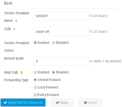
5. Configure VLAN 2 as the default VLAN.
Figure 7 Specifying the default VLAN
Verifying the configuration
1. Make the client access the WLAN.
2. Click the Network View tab at the bottom of the page.
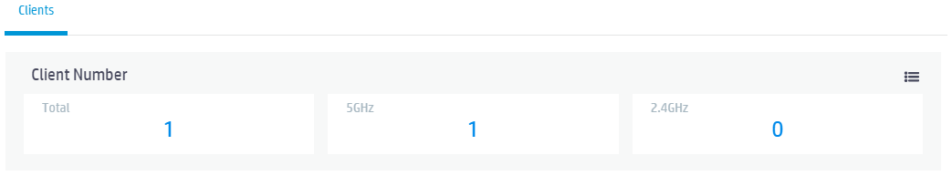
3. From the navigation pane, select Monitoring > Clients, and verify that a client is online.
Figure 8 Displaying online client quantity
4. Click the More icon in the upper right corner of the Client Number area to view detailed client information.
Figure 9 Displaying detailed online client information
![]()
Related documentation
H3C Access Controllers Web-Based Configuration Guide
