- Table of Contents
-
- 05-Web configuration examples (AC+fit AP)
- 01-Telnet Access Control Configuration Example
- 02-IPv6 Telnet Access Control Configuration Example
- 03-Web Access Control Configuration Example
- 04-User Role Assignment for Local Web Authentication Users Configuration Example
- 05-SSH Local Authentication Configuration Example
- 06-SSH User Remote Password Authentication Configuration Example
- 07-IPv6 SSH User Remote Password Authentication Configuration Example
- 08-Password Control Configuration Example
- 09-Licensing Configuration Example
- 10-Automatic License Installation Configuration Example
- 11-Layer 2 Static Link Aggregation Configuration Example
- 12-Layer 2 Dynamic Link Aggregation Configuration Example
- 13-PPPoE Client Configuration Example
- 14-Static IPv6 Address Configuration Example
- 15-IPv6 Static Routing Configuration Example
- 16-Static IPv4 DNS Configuration Example
- 17-Static IPv6 DNS Configuration Example
- 18-IGMP Snooping Configuration Example
- 19-MLD Snooping Configuration Example
- 20-IPv4 DNS Proxy Configuration Example
- 21-IPv6 DNS Proxy Configuration Example
- 22-Static NAT Configuration Example
- 23-Dynamic NAT Configuration Example
- 24-IPv4 ACL-Based Packet Filter Configuration Example
- 25-IPv6 ACL-Based Packet Filter Configuration Example
- 26-ARP Attack Protection Configuration Example
- 27-ARP Proxy Configuration Example
- 28-Dynamic IPv4 DNS Configuration Example
- 29-Dynamic IPv6 DNS Configuration Example
- 30-WLAN Access Configuration Example
- 31-Different Wireless Services on Different Radios Configuration Example
- 32-CAPWAP Tunnel Establishment Through DHCP Configuration Example
- 33-CAPWAP Tunnel Establishment Through DHCPv6 Configuration Example
- 34-CAPWAP Tunnel Establishment Through DNS Configuration Example
- 35-CAPWAP Tunnel Establishment Through DNSv6 Configuration Example
- 36-Auto AP Configuration Example
- 37-AP Group Configuration Example
- 38-Radio Management Configuration Example
- 39-Load Balancing Group-Based Session-Mode Load Balancing Configuration Example
- 40-Radio-Based Session-Mode Load Balancing Configuration Example
- 41-A-MPDU and A-MSDU Configuration Example
- 42-Device Classification and Countermeasure Configuration Example
- 43-Malformed Packet Detection and Flood Attack Detection Configuration Example
- 44-Signature-Based Attack Detection Configuration Example
- 45-802.1X RADIUS-Based AAA Configuration Example
- 46-VLAN Interface-Based Direct Portal Authentication Configuration Example
- 47-Service Template-Based Direct Portal Authentication Configuration Example
- 48-Wireless Spectrum Analysis Configuration Example
- 49-Auto DFS Configuration Examples
- 50-Auto TPC Configuration Examples
- 51-Whitelist-Based Client Access Control Configuration Example
- 52-Blacklist-Based Client Access Control Configuration Example
- 53-CAC Configuration Example
- 54-WLAN Probe Configuration Example
- 55-Intra-AC Roaming Configuration Example
- 56-Bonjour Gateway Configuration Example
- 57-IPv4 Multicast Optimization Configuration Examples
- 58-IPv6 Multicast Optimization Configuration Examples
- 59-Ping Configuration Example
- 60-Local Packet Capture Configuration Example
- 61-Remote Packet Capture Configuration Example
- Related Documents
-
| Title | Size | Download |
|---|---|---|
| 12-Layer 2 Dynamic Link Aggregation Configuration Example | 231.66 KB |
|
|
|
H3C Access Controllers |
|
Comware 7 Layer 2 Dynamic Link Aggregation |
|
Configuration Example |
Copyright © 2022 New H3C Technologies Co., Ltd. All rights reserved.
No part of this manual may be reproduced or transmitted in any form or by any means without prior written consent of New H3C Technologies Co., Ltd.
Except for the trademarks of New H3C Technologies Co., Ltd., any trademarks that may be mentioned in this document are the property of their respective owners.
The information in this document is subject to change without notice.
Contents
Example: Configuring a Layer 2 dynamic link aggregation group
Configuring an aggregation group on AC 1
Configuring an aggregation group on AC 2
Overview
The following information provides an example for configuring Layer 2 dynamic link aggregation.
Prerequisites
The following information applies to Comware 7-based access controllers. Procedures and information in the examples might be slightly different depending on the software or hardware version of the H3C access controllers.
The configuration examples were created and verified in a lab environment, and all the devices were started with the factory default configuration. When you are working on a live network, make sure you understand the potential impact of every command on your network.
The following information is provided based on the assumption that you have basic knowledge of Layer 2 dynamic link aggregation.
Example: Configuring a Layer 2 dynamic link aggregation group
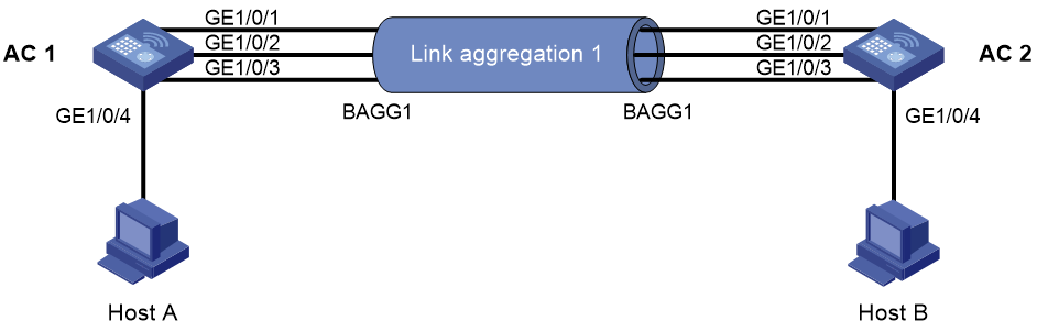
Network configuration
As shown in Figure 1, set up a dynamic aggregate link between AC 1 and AC 2.
Procedures
Configuring an aggregation group on AC 1
1. Click the System View tab at the bottom of the page.
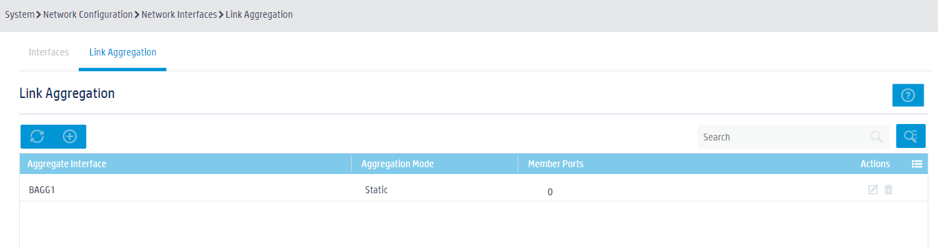
2. From the navigation pane, select Network Settings > Interfaces > Link Aggregation.
3. Click the Create button ![]() to create aggregation group 1.
to create aggregation group 1.
Figure 2 Creating an aggregation group
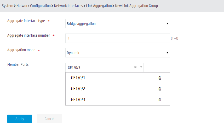
4. Set the aggregation mode to dynamic and assign GigabitEthernet 1/0/1 through GigabitEthernet 1/0/3 to aggregation group 1.
Figure 3 Configuring an aggregation group
5. Click the System View tab at the bottom of the page.
6. From the navigation pane, select Network Settings > VLAN.
Figure 4 VLAN list
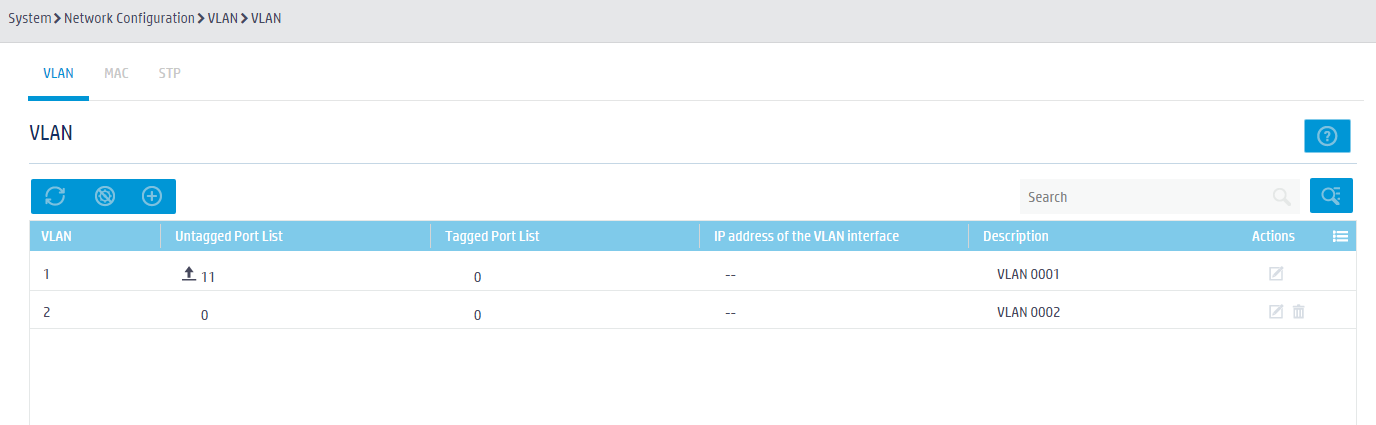
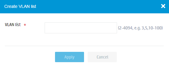
7. Click the Create VLANs
button ![]() to create VLAN 10.
to create VLAN 10.
Figure 5 Creating a VLAN
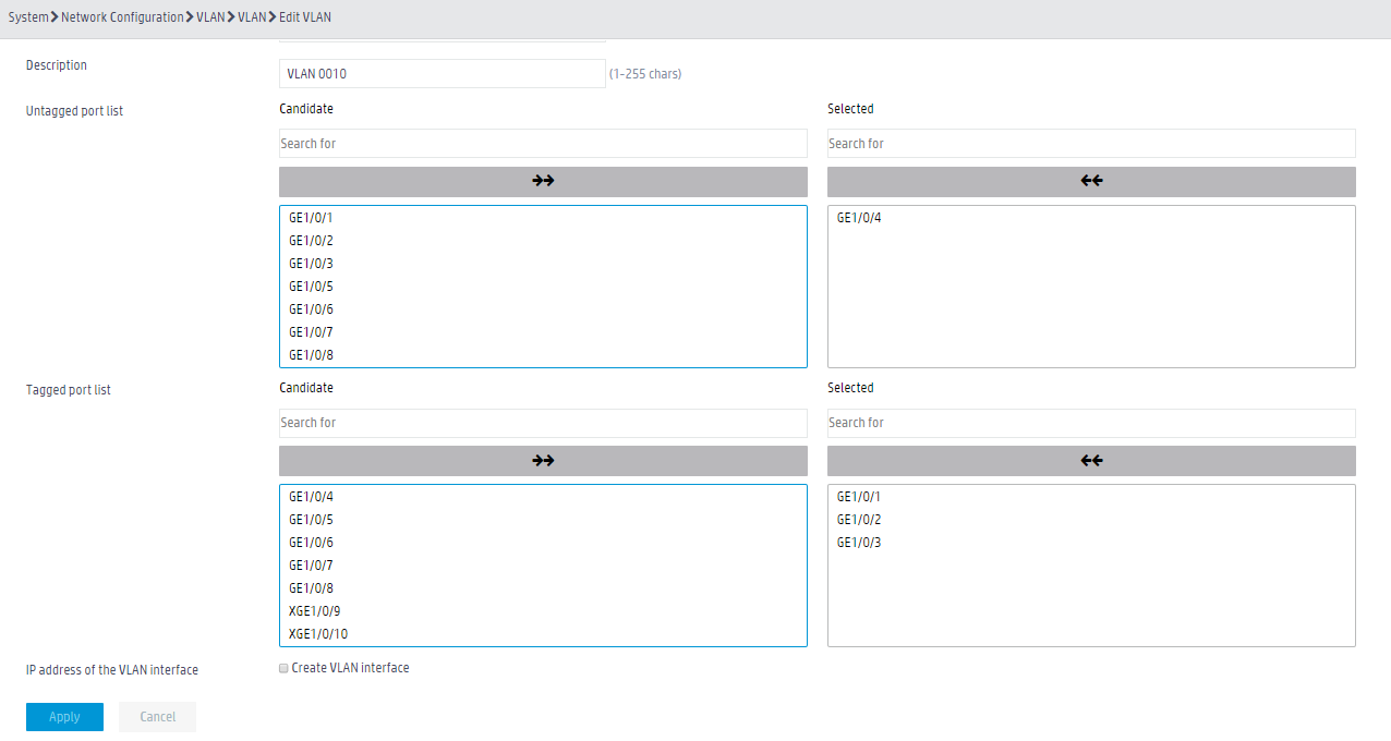
8. Click the Edit
button ![]() for VLAN 10 to assign GigabitEthernet 1/0/4 as an untagged member and GigabitEthernet 1/0/1 through GigabitEthernet 1/0/3 as tagged
members to the VLAN.
for VLAN 10 to assign GigabitEthernet 1/0/4 as an untagged member and GigabitEthernet 1/0/1 through GigabitEthernet 1/0/3 as tagged
members to the VLAN.
Figure 6 Adding physical interfaces
Configuring an aggregation group on AC 2
Configure AC 2 in the same way you configured AC 1. (Details not shown.)
Verifying the configuration
1. Verify that GigabitEthernet 1/0/1 through GigabitEthernet 1/0/3 have been assigned to aggregation group 1 on the ACs. (Details not shown.)
2. Verify that Host A can ping Host B. (Details not shown.)
3. Verify that Host A can ping Host B when one of the links between the ACs fails. (Details not shown.)
Related documentation
H3C Access Controllers Web-Based Configuration Guide
