- Table of Contents
-
- H3C WX Series Access Controllers Web-Based Configuration Guide(R3308 R2308)-6W107
- 00-Preface
- 01-About the WX Series Access Controllers Web Configuration Guide
- 02-Quick Start
- 03-Web Overview
- 04-Summary
- 05-Device
- 06-Network
- 07-AP Configuration
- 08-Wireless Service
- 09-WLAN Roaming Configuration
- 10-Radio Configuration
- 11-Authentication
- 12-Security
- 13-QoS configuration
- 14-Advanced Settings
- 15-Stateful Failover Configuration
- Related Documents
-
| Title | Size | Download |
|---|---|---|
| 15-Stateful Failover Configuration | 242.98 KB |
Contents
Introduction to stateful failover
Introduction to stateful failover states
Stateful failover configuration example
|
|
NOTE: Support for the stateful failover feature may vary depending on your device model. For more information, see "Feature matrixes." |
Overview
Introduction to stateful failover
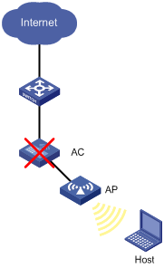
Some customers require their wireless networks to be highly reliable to ensure continuous data transmission. In Figure 1, deploying only one AC (even with high reliability) risks a single point of failure and therefore cannot meet the requirement.
Figure 1 Network with one AC deployed
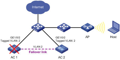
The stateful failover feature (supporting portal service) was introduced to meet the requirement. In Figure 2, two ACs that are enabled with stateful failover are deployed in the network. You need to specify a VLAN on the two ACs as the backup VLAN, and add the interfaces between the ACs to the backup VLAN. The backup VLAN is like a failover link, through which the two ACs exchange state negotiation messages periodically. After the two ACs enter the synchronization state, they back up the service entries of each other to make sure that the service entries on them are consistent. If one AC fails, the other AC, which has already backed up the service information, can take over the services, thus avoiding service interruption.
Figure 2 Network diagram for stateful failover
Introduction to stateful failover states
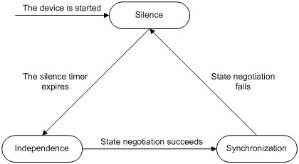
The stateful failover states include:
· Silence: Indicates that the device has just started, or is transiting from synchronization state to independence state.
· Independence: Indicates that the silence timer has expired, but no failover link is established.
· Synchronization: Indicates that the device has completed state negotiation with the other device and is ready for data backup.
The following figure shows state relations.
Figure 3 Stateful failover state diagram
Configuring stateful failover
1. Select High reliability > Stateful Failover from the navigation tree to enter the stateful failover configuration page, as shown in Figure 4.
2. View the current stateful failover state at the lower part of the page as described in Table 2.
Figure 4 Stateful failover configuration page
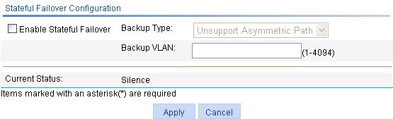
3. Configure stateful failover parameters at the upper part of the page as described in Table 1.
4. Click Apply.
|
Item |
Description |
|
Enable Stateful Failover |
Enable/disable the stateful failover feature. |
|
Backup Type |
Select whether to support asymmetric path. · Unsupport Asymmetric Path. In this mode, sessions enter and leave the internal network through one device. The two devices work in the active/standby mode. · Support Asymmetric Path. In this mode, sessions enter and leave the internal network through different devices to achieve load sharing. The two devices work in the active/active mode. |
|
Backup VLAN |
Set the backup VLAN. After a VLAN is configured as a backup VLAN, the interface(s) in the VLAN is used to transmit stateful failover packets.
· A device uses VLAN tag+protocol number to identify stateful failover packets, and broadcasts stateful failover packets to the peer within the backup VLAN. Therefore, H3C does not recommend that you configure other services (such as voice VLAN) for a backup VLAN to avoid impact on the operation of stateful failover. · An interface added to the backup VLAN can transmit other packets besides stateful failover packets. |
|
Field |
Description |
|
Current Status |
Displays the failover state of the device. |
Stateful failover configuration example
Network requirements
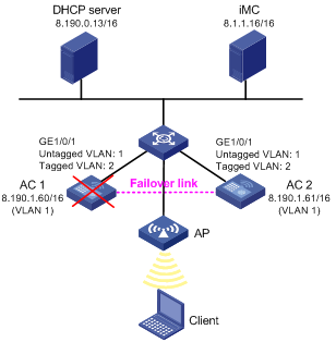
In Figure 5, the IP address of VLAN-interface 1 on AC 1 is 8.190.1.60/16, and that on AC 2 is 8.190.1.61/16. The client and AP each obtain an IP address from the DHCP server at 8.190.0.13/16, and the ACs perform portal authentication through the IMC server. Configure stateful failover on AC 1 and AC 2 so that when one AC fails, the other AC can take over portal and other services.
|
|
NOTE: The portal group configuration on the two ACs must be consistent. |
Configuring AC 1
1. Configure the backup AC and enable fast backup:
a. Select Advanced > AC Backup from the navigation tree to enter the default Setup page, as shown in Figure 6.
b. Select the IPv4 box and type the IP address of AC 2 (8.190.1.61) as the backup AC address, and select enable from the Fast Backup Mode list.
c. Click Apply.

2. Configure stateful failover:
a. Select High reliability > Stateful Failover from the navigation tree, as shown in Figure 7.
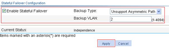
b. Select the Enable Stateful Failover box, select Unsupport Asymmetric Path from the Backup Type list, and Type 2 for Backup VLAN.
c. Click Apply.
Figure 7 Configuring stateful failover
3. Configure RADIUS scheme system:
a. Select Authentication > RADIUS from the navigation tree.
b. Click Add to enter the RADIUS scheme configuration page.
c. Type system for Scheme Name, select Extended for Server Type, and select Without domain name for Username Format.
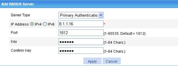
d. Click Add in the RADIUS Server Configuration field to enter the page as shown in Figure 8.
e. Select Primary Authentication for Server Type, specify an IPv4 address 8.1.1.16 and 1812 as the port number.
f. Type expert for Key and expert for Confirm Key.
g. Click Apply.
Figure 8 Configuring a primary RADIUS authentication server
h. Click Add in the RADIUS Server Configuration field to enter the page as shown in Figure 9.
i. Select Primary Accounting for Server Type, and specify an IPv4 address 8.1.1.16 and 1813 as the port number.
j. Type expert for Key and expert for Confirm Key.
k. Click Apply.
Figure 9 Configuring a RADIUS accounting server

l. After the configurations are complete, the RADIUS scheme configuration page is as shown in Figure 10. Click Apply.
Figure 10 RADIUS scheme configuration page

4. Configure AAA authentication scheme for ISP domain system:
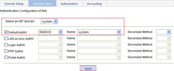
a. Click the Authentication tab.
b. Select system from the Select an ISP domain list, and select the Default AuthN box.
c. Select RADIUS from the list, and system from the Name list.
d. Click Apply.
A dialog box appears, showing the configuration progress.
e. After the configuration is successfully applied, click Close.
Figure 11 Configuring AAA authentication scheme for the ISP domain
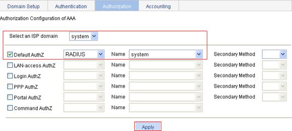
5. Configure AAA authorization scheme for ISP domain system:
a. Click the Authorization tab.
b. Select system from the Select an ISP domain list, and select the Default AuthZ box.
c. Select RADIUS from the list and system from the Name list.
d. Click Apply.
A dialog box appears, showing the configuration progress.
e. After the configuration is successfully applied, click Close.
Figure 12 Configuring AAA authorization scheme for the ISP domain
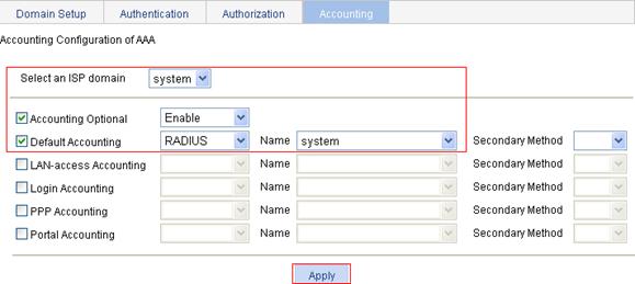
6. Configure AAA accounting scheme for ISP domain system:
a. Click the Accounting tab.
b. Select system from the Select an ISP domain list, and select the Accounting Optional box.
c. Select Enable from the list, and select the Default Accounting box.
d. Select RADIUS from the list and system from the Name list.
e. Click Apply.
A dialog box appears, showing the configuration progress.
f. After the configuration is successfully applied, click Close.
Figure 13 Configuring AAA accounting scheme for the ISP domain
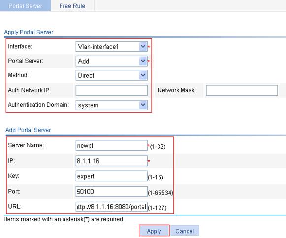
7. Configure portal authentication:
a. Select Authentication > Portal from the navigation tree to enter the default Portal Server configuration page as shown in Figure 14.
b. Click Add.
c. Select Vlan-interface1 from the Interface list, Add from the Portal Server list, and Direct from the Method list, and select system for Authentication Domain.
d. Type newpt for Server Name, 8.1.1.16 for IP, expert for Key, 50100 for Port, and http://8.1.1.16:8080/portal for URL.
e. Click Apply.
Figure 14 Configuring a portal server
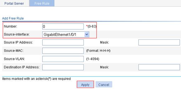
8. Add a portal-free rule:
a. Click the Free Rule tab.
b. Click Add.
c. Type 0 for Number, and select GigabitEthernet1/0/1 as the source interface.
d. Click Apply.
Figure 15 Adding a portal-free rule
9. Configure portal to support stateful failover at the command line interface (CLI):
# Specify AC 1's device ID to be used in stateful failover mode as 1, and specify portal group 2 for interface VLAN-interface 1.
<AC1>system-view
[AC1]nas device-id 1
[AC1]interface Vlan-interface 1
[AC1-Vlan-interface1]portal backup-group 2
# Configure the virtual IP address of VRRP group 1 as 8.190.1.100, and specify the priority of AC 1 as 200. AC 2 uses the default priority.
[AC1-Vlan-interface1]vrrp vrid 1 virtual-ip 8.190.1.100
[AC1-Vlan-interface1]vrrp vrid 1 priority 200
[AC1-Vlan-interface1]quit
# Configure the source IP address for RADIUS packets as 8.190.1.100.
[AC1]radius nas-ip 8.190.1.100
# Configure the source IP address for portal packets as 8.190.1.100 (same as the AC's IP address configured on the IMC server for portal authentication).
[AC1-Vlan-interface1]portal nas-ip 8.190.1.100
Configuring AC 2.
The configuration on AC 2 is similar to that on AC 1 except that:
· When you configure AC backup, specify AC 1's IP address as the backup AC address.
· Specify the device ID to be used in stateful failover mode as 2.
For more information, see the configuration on AC 1.
Configuration guidelines
When you configure stateful failover, follow these guidelines:
· You must configure the 1+1 AC backup function to make sure that the traffic can automatically switch to the other device if one device fails. For more information, see "Advanced settings."
· To back up portal related information from the active device to the standby device, you must configure portal to support stateful failover besides the configurations described in this chapter. For more information, see WX Series Access Controllers Security Configuration Guide.
· Stateful failover can be implemented only between two devices rather than among more than two devices.
