- Table of Contents
-
- H3C WX Series Access Controllers Web-Based Configuration Guide(R3308 R2308)-6W107
- 00-Preface
- 01-About the WX Series Access Controllers Web Configuration Guide
- 02-Quick Start
- 03-Web Overview
- 04-Summary
- 05-Device
- 06-Network
- 07-AP Configuration
- 08-Wireless Service
- 09-WLAN Roaming Configuration
- 10-Radio Configuration
- 11-Authentication
- 12-Security
- 13-QoS configuration
- 14-Advanced Settings
- 15-Stateful Failover Configuration
- Related Documents
-
| Title | Size | Download |
|---|---|---|
| 11-Authentication | 1012.90 KB |
Contents
Recommended configuration procedure
Configuring portal authentication
Introduction to portal authentication
Configuring portal authentication
Recommended configuration procedure
Configuring the portal service
Configuring advanced parameters for portal authentication
Configuring a portal-free rule
Customizing authentication pages
Portal authentication configuration example
Recommended configuration procedure
Configuring authentication methods for the ISP domain
Configuring authorization methods for the ISP domain
Configuring accounting methods for the ISP domain
Configuring the local EAP service
Local EAP service configuration example
Recommended configuration procedure for manual request
Recommended configuration procedure for automatic request
Retrieving and displaying a certificate
Requesting a local certificate
Retrieving and displaying a CRL
Certificate management configuration example
802.1X is a port-based network access control protocol initially proposed by the IEEE 802 LAN/WAN committee for the security of wireless LANs (WLANs). It has been widely used on Ethernet networks for access control.
802.1X controls network access by authenticating the devices connected to 802.1X-enabled LAN ports.
You can also configure the port security feature to perform 802.1X. Port security combines and extends 802.1X and MAC authentication. It applies to a network, a WLAN, for example, that requires different authentication methods for different users on a port. Port security is beyond the scope of this chapter. It is described in Security Configuration Guide for the product.
802.1X architecture
802.1X operates in the client/server model. It comprises three entities: client (the supplicant), the network access device (the authenticator), and the authentication server, as shown in Figure 1.
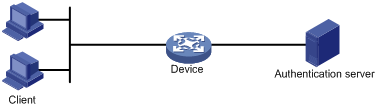
· The client is a user terminal seeking access to the LAN. It must have 802.1X software to authenticate to the network access device.
· The network access device authenticates the client to control access to the LAN. In a typical 802.1X environment, the network access device uses an authentication server to perform authentication.
· The authentication server is the entity that provides authentication services for the network access device. It authenticates 802.1X clients by using the data sent from the network access device, and returns the authentication results for the network access device to make access decisions. The authentication server is typically a Remote Authentication Dial-in User Service (RADIUS) server. In a small LAN, you can also use the network access device as the authentication server.
For more information about the 802.1X protocol, see H3C WX Series Access Controllers Security Configuration Guide.
Access control methods
H3C implements port-based access control as defined in the 802.1X protocol, and extends the protocol to support MAC-based access control.
· With port-based access control, once an 802.1X user passes authentication on a port, any subsequent user can access the network through the port without authentication. When the authenticated user logs off, all other users are logged off.
· With MAC-based access control, each user is separately authenticated on a port. When a user logs off, no other online users are affected.
Configuring 802.1X
Configuration prerequisites
· Configure an ISP domain and AAA scheme (local or RADIUS authentication) for 802.1X users. For more information, see "Configuring AAA" and "Configuring RADIUS."
· If RADIUS authentication is used, create user accounts on the RADIUS server.
· If local authentication is used, create local user accounts on the access device and set the service type to LAN-access.
· If you want to use EAP relay when the RADIUS server does not support any EAP authentication method or no RADIUS server is available, configure the EAP server function on your network access device.
|
|
NOTE: Configure 802.1X on a wired port. Wireless ports support only the port security feature, and the port security is enabled by default on the wireless ports. |
Recommended configuration procedure
|
Task |
Description |
|
Required. Enable 802.1X authentication globally and configure the authentication method and advanced parameters. By default, 802.1X authentication is disabled globally. |
|
|
Required. Enable 802.1X authentication on specified ports and configure 802.1X parameters for the ports. By default, 802.1X authentication is disabled on a port. |
Configuring 802.1X globally
1. From the navigation tree, select Authentication > 802.1X.
Figure 2 802.1X global configuration
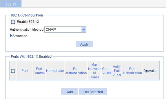
2. In the 802.1X Configuration area, select the Enable 802.1X box.
3. Select an authentication method for 802.1X users. Options include CHAP, PAP, and EAP.
¡ CHAP—Sets the access device to perform EAP termination and use the CHAP to communicate with the RADIUS server.
¡ PAP—Sets the access device to perform EAP termination and use the PAP to communicate with the RADIUS server.
¡ EAP—Sets the access device to relay EAP packets, and supports any of the EAP authentication methods to communicate with the RADIUS server.
|
|
NOTE: When you configure EAP relay or EAP termination, consider the following factors: · Whether the RADIUS server supports EAP packets. · The authentication methods supported by the 802.1X client and the RADIUS server. If the client is using only MD5-Challenge EAP authentication or the "username + password" EAP authentication initiated by an H3C iNode 802.1X client, you can use both EAP termination and EAP relay. To use EAP-TL, PEAP, or any other EAP authentication methods, you must use EAP relay. |
4. Click Advanced to expand the advanced 802.1X configuration area.
Figure 3 Advanced configuration
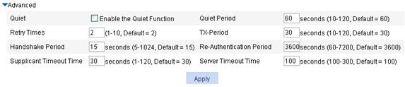
5. Configure advanced 802.1X settings as described in Table 1.
6. Click Apply.
|
Item |
Description |
|
|
Quiet |
Specify whether to enable the quiet timer. The quiet timer enables the network access device to wait a period of time before it can process any authentication request from a client that has failed an 802.1X authentication. |
|
|
Quiet Period |
Set the value of the quiet timer. |
|
|
Retry Times |
Set the maximum number of authentication request attempts. The network access device retransmits an authentication request if it receives no response to the request it has sent to the client within a period of time (specified by using the TX Period option or the Supplicant Timeout Time option). The network access device stops retransmitting the request, if it has made the maximum number of request transmission attempts but still received no response. |
|
|
TX Period |
Set the username request timeout timer. · The timer starts when the device sends an EAP-Request/Identity packet to a client in response to an authentication request. If the device receives no response before this timer expires, it retransmits the request. · The timer also sets the interval at which the network device sends multicast EAP-Request/Identity packets to detect clients that cannot actively request authentication. |
|
|
Handshake Period |
Set the handshake timer. The timer sets the interval at which the access device sends client handshake requests to check the online status of a client that has passed authentication. If the device receives no response after sending the maximum number of handshake requests, it considers that the client has logged off. For information about how to enable the online user handshake function, see "Configuring 802.1X on a port." |
|
|
Re-Authentication Period |
Set the periodic online user re-authentication timer. The timer sets the interval at which the network device periodically re-authenticates online 802.1X users. The change to the periodic re-authentication timer applies to the users that have been online only after the old timer expires. For information about how to enable periodic online user re-authentication on a port, see "Configuring 802.1X on a port." |
|
|
Supplicant Timeout Time |
Set the client timeout timer. The timer starts when the access device sends an EAP-Request/MD5 Challenge packet to a client. If no response is received when this timer expires, the access device retransmits the request to the client. |
You can set the client timeout timer to a high value in a low-performance network, and adjust the server timeout timer to adapt to the performance of different authentication servers. In most cases, the default settings are sufficient. |
|
Server Timeout Time |
Set the server timeout timer. The timer starts when the access device sends a RADIUS Access-Request packet to the authentication server. If no response is received when this timer expires, the access device retransmits the request to the server. |
|
|
|
IMPORTANT: Do not change the timer parameters of global 802.1X from their default values unless you have determined that the changes would better the interaction process. |
Configuring 802.1X on a port
1. From the navigation tree, select Authentication > 802.1X to enter the page, as shown in Figure 2.
The Ports With 802.1X Enabled area shows the 802.1X configuration on ports.
2. Click Add.
Figure 4 802.1X configuration on a port
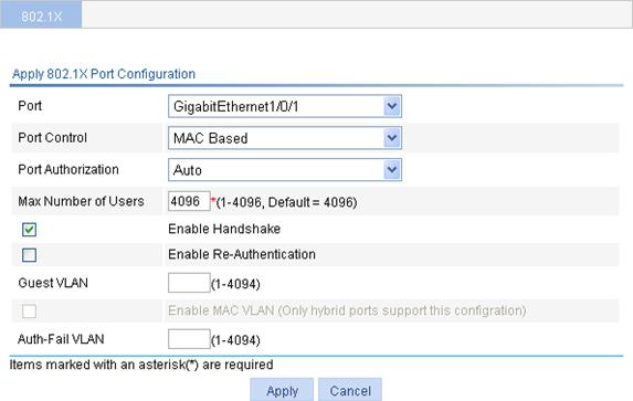
3. Configure 802.1X features on a port as described in Table 2.
4. Click Apply.
|
Item |
Description |
|
Port |
Select the port to be enabled with 802.1X authentication. Only 802.1X-disabled ports are available. NOTE: 802.1X is mutually exclusive with link aggregation group configuration on a port. |
|
Port Control |
Set the access control method for the port, which can be MAC Based or Port Based. NOTE: To use both 802.1X and portal authentication on a port, you must select MAC Based. |
|
Port Authorization |
Select the port authorization state for 802.1X. Options include: · Auto—Places the port initially in unauthorized state to allow only EAPOL packets to pass, and after a user passes authentication, sets the port in authorized state to allow access to the network. You can use this option in most scenarios. · Force-Authorized—Places the port in authorized state, enabling users on the port to access the network without authentication. · Force-Unauthorized—Places the port in unauthorized state, denying any access requests from users on the port. |
|
Max Number of Users |
Set the maximum number of concurrent 802.1X users on the port. |
|
Enable Handshake |
Specify whether to enable the online user handshake function. The online user handshake function checks the connectivity status of online 802.1X users. The network access device sends handshake messages to online users at the interval specified by the Handshake Period setting. If no response is received from an online user after the maximum number of handshake attempts (set by the Retry Times setting) has been made, the network access device sets the user in offline state. For information about the timers, see Table 1. NOTE: If the network has 802.1X clients that cannot exchange handshake packets with the network access device, disable the online user handshake function to prevent their connections from being inappropriately torn down. |
|
Enable Re-Authentication |
Specify whether to enable periodic online user re-authentication on the port. Periodic online user re-authentication tracks the connection status of online users and updates the authorization attributes assigned by the server, such as the ACL, and VLAN. The re-authentication interval is specified by the Re-Authentication Period setting in Table 1. NOTE: · The periodic online user re-authentication timer can also be set by the authentication server in the session-timeout attribute. The server-assigned timer overrides the timer setting on the access device, and enables periodic online user re-authentication, even if the function is not configured. Support for the server assignment of re-authentication timer and the re-authentication timer configuration on the server vary with servers. · The VLAN assignment status must be consistent before and after re-authentication. If the authentication server has assigned a VLAN before re-authentication, it must also assign a VLAN at re-authentication. If the authentication server has assigned no VLAN before re-authentication, it must not assign one at re-authentication. Violation of either rule can cause the user to be logged off. The VLANs assigned to an online user before and after re-authentication can be the same or different. |
|
Guest VLAN |
Specify an existing VLAN as the guest VLAN. For more information, see "Configuring an 802.1X guest VLAN." |
|
Enable MAC VLAN |
Select the box to enable MAC-based VLAN. NOTE: Only hybrid ports support the feature. |
|
Auth-Fail VLAN |
Specify an existing VLAN as the Auth-Fail VLAN to accommodate users that have failed 802.1X authentication. For more information, see "Configuring an Auth-Fail VLAN." |
Configuring an 802.1X guest VLAN
· Configuration guidelines:
¡ You can configure only one 802.1X guest VLAN on a port. The 802.1X guest VLANs on different ports can be different.
¡ Assign different IDs for the default VLAN, and 802.1X guest VLAN on a port, so the port can correctly process incoming VLAN tagged traffic.
¡ With 802.1X authentication, a hybrid port is always assigned to a VLAN as an untagged member. After the assignment, do not re-configure the port as a tagged member in the VLAN.
¡ Use Table 3 when you configure multiple security features on a port.
Table 3 Relationships of the 802.1X guest VLAN and other security features
|
Feature |
Relationship description |
|
MAC authentication guest VLAN on a port that performs MAC-based access control |
Only the 802.1X guest VLAN take effect. A user that fails MAC authentication will not be assigned to the MAC authentication guest VLAN. |
|
802.1X Auth-Fail VLAN on a port that performs MAC-based access control |
The 802.1X Auth-Fail VLAN has a higher priority. |
|
Port intrusion protection on a port that performs MAC-based access control |
The 802.1X guest VLAN function has higher priority than the block MAC action but lower priority than the shut down port action of the port intrusion protection feature. |
· Configuration prerequisites:
¡ Create the VLAN to be specified as the 802.1X guest VLAN.
¡ If the 802.1X-enabled port performs port-based access control, enable 802.1X multicast trigger at the command-line interface (CLI). (802.1X multicast trigger is enabled by default.)
¡ If the 802.1X-enabled port performs MAC-based access control, configure the port as a hybrid port, enable MAC-based VLAN on the port, and assign the port to the 802.1X guest VLAN as an untagged member.
Configuring an Auth-Fail VLAN
· Configuration guidelines:
¡ Assign different IDs for the default VLAN, and 802.1X Auth-Fail VLAN on a port, so the port can correctly process VLAN tagged incoming traffic.
¡ Use Table 4 when you configure multiple security features on a port.
Table 4 Relationships of the 802.1X Auth-Fail VLAN with other features
|
Feature |
Relationship description |
|
MAC authentication guest VLAN on a port that performs MAC-based access control |
The 802.1X Auth-Fail VLAN has a high priority. |
|
Port intrusion protection on a port that performs MAC-based access control |
The 802.1X Auth-Fail VLAN function has higher priority than the block MAC action but lower priority than the shut down port action of the port intrusion protection feature. |
· Configuration prerequisites:
¡ Create the VLAN to be specified as the 802.1X Auth-Fail VLAN.
¡ If the 802.1X-enabled port performs port-based access control, enable 802.1X multicast trigger. (802.1X multicast trigger is enabled by default.)
¡ If the 802.1X-enabled port performs MAC-based access control, configure the port as a hybrid port, enable MAC-based VLAN on the port, and assign the port to the Auth-Fail VLAN as an untagged member.
Configuring portal authentication
Introduction to portal authentication
With portal authentication, an access device forces all users to log onto the portal website first. Every user can access the free services provided on the portal website; but to access the Internet, a user must pass portal authentication on the portal website.
A user can access a known portal website and enter username and password for authentication. This authentication mode is called active authentication. There is also another authentication mode, forced authentication, in which the access device forces a user trying to access the Internet through HTTP to log on to a portal website for authentication.
The portal feature provides the flexibility for Internet service providers (ISPs) to manage services. A portal website can, for example, present advertisements, and deliver community services and personalized services. In this way, broadband network providers, equipment vendors, and content service providers form an industrial ecological system.
A typical portal system comprises these basic components: authentication client, access device, portal server, authentication/accounting server, and security policy server.
Figure 5 Portal system components
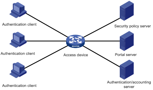
The components of a portal system interact in the following procedure:
1. When an unauthenticated user enters a website address in the address bar of the browser to access the Internet, an HTTP request is created and sent to the access device, which redirects the HTTP request to the web authentication homepage of the portal server. For extended portal functions, authentication clients must run the portal client software.
2. On the authentication homepage/authentication dialog box, the user enters and submits the authentication information, which the portal server then transfers to the access device.
3. Upon receipt of the authentication information, the access device communicates with the authentication/accounting server for authentication and accounting.
4. After successful authentication, the access device checks whether there is a corresponding security policy for the user. If not, it allows the user to access the Internet. Otherwise, the client communicates with the access device and the security policy server for security check. If the client passes security check, the security policy server authorizes the user to access the Internet resources.
|
|
NOTE: The web interface of the device supports configuring portal authentication only on Layer 3 interfaces. For more information about portal authentication, see H3C WX Series Access Controllers Security Configuration Guide. |
Configuring portal authentication
Configuration prerequisites
The portal feature provides a solution for user identity authentication and security checking. However, the portal feature cannot implement this solution by itself. RADIUS authentication needs to be configured on the access device to cooperate with the portal feature to complete user authentication.
The prerequisites for portal authentication configuration are as follows:
· The portal authentication-enabled interfaces of the access device are configured with valid IP addresses or have obtained valid IP addresses through DHCP.
· The portal server and the RADIUS server have been installed and configured properly. Local portal authentication requires no independent portal server.
· With re-DHCP authentication, the invalid IP address check function of DHCP relay is enabled on the access device, and the DHCP server is installed and configured properly.
· With RADIUS authentication, usernames and passwords of the users are configured on the RADIUS server, and the RADIUS client configurations are performed on the access device. For information about RADIUS client configuration, see "Configuring RADIUS."
· To implement extended portal functions, install and configure IMC EAD, and make sure that the ACLs configured on the access device correspond to those specified for the resources in the quarantined area and for the restricted resources on the security policy server. For information about security policy server configuration on the access device, see "Configuring RADIUS."
Recommended configuration procedure
|
Step |
Remarks |
|
Required. Configure a portal server, apply the portal server to a Layer 3 interface, and configure the portal authentication parameters. By default, no portal server is configured. |
|
|
2. Configuring advanced parameters for portal authentication |
Optional. Specify an auto redirection URL, set the time that the device must wait before redirecting an authenticated user to the auto redirection URL, and add web proxy server port numbers. |
|
Optional. Configure a portal-free rule, specifying the source and destination information for packet filtering. A portal-free rule allows specified users to access specified external websites without portal authentication. Packets matching a portal-free rule will not trigger portal authentication and the users can directly access the specified external websites. By default, no portal-free policy is configured. |
Configuring the portal service
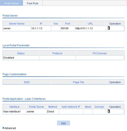
1. Select Authentication > Portal from the navigation tree.
The portal server configuration page appears.
Figure 6 Portal server configuration
|
|
TIP: On the page shown in Figure 6, the portal service applied on a Layer 3 interface can be in either of the following states: · Running—Portal authentication has taken effect on the interface. · Enabled—Portal authentication has been enabled on the interface but has not taken effect. |
2. Click Add to enter the portal service application page.
Figure 7 Portal service application
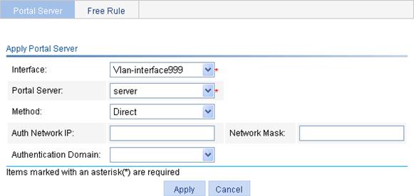
3. Configure the portal application settings as described in Table 5.
4. Click Apply.
|
Item |
Description |
|
Interface |
Specify the Layer 3 interface to be enabled with portal authentication. |
|
Portal Server |
Specify the portal server to be applied on the specified interface. Options include: · Select Server—Select an existing portal server from the Portal Server list. · New Server—If you select this option from the list, the portal server configuration area, as shown in Figure 8, will be displayed at the lower part of the page. You can add a remote portal server and apply the portal server to the interface. For detailed configuration, see Table 6. · Enable Local Server—If you select this option from the list, the local portal service configuration area, as shown in Figure 9, will be displayed at the lower part of the page. You can configure the parameters for local portal service. For detailed configuration, see Table 7. |
|
Method |
Specify the portal authentication mode, which can be: · Direct—Direct portal authentication. · Layer3—Cross-subnet portal authentication. · Re DHCP—Re-DHCP portal authentication.
· In cross-subnet portal authentication mode, Layer 3 forwarding devices are not required to be present between the authentication client and the access device. However, if they are present, you must select the cross-subnet portal authentication mode. · In re-DHCP portal authentication mode, a client is allowed to send out packets using a public IP address before it passes portal authentication. However, responses of the packets are restricted. · If the local portal server is used, you can configure the re-DHCP mode but it does not take effect. |
|
Auth Network IP |
Specify the IP address and mask of the authentication subnet. This field is configurable when you select the Layer3 mode (cross-subnet portal authentication). By configuring an authentication subnet, you specify that only HTTP packets from users on the authentication subnet can trigger portal authentication. If an unauthenticated user is not on any authentication subnet, the access device discards all the user's HTTP packets that do not match any portal-free rule.
The authentication subnet in direct mode is any source IP address, and that in re-DHCP mode is the private subnet to which the interface's private IP address belongs. |
|
Network Mask |
|
|
Authentication Domain |
Specify the authentication domain for Layer 3 portal users. After you specify an authentication domain on a Layer 3 interface, the device will use the authentication domain for authentication, authorization, and accounting (AAA) of the portal users on the interface, ignoring the domain names carried in the usernames. You can specify different authentication domains for different interfaces as needed. The available authentication domains are those specified on the page you enter by selecting Authentication > AAA from the navigation tree. For more information, see "Configuring AAA." |
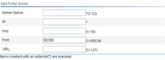
Figure 8 Adding a portal server
|
Item |
Description |
|
Server Name |
Enter a name for the remote portal server. |
|
IP |
Enter the IP address of the remote portal server. |
|
Key |
Enter the shared key to be used for communication between the device and the remote portal server. |
|
Port |
Enter the port number of the remote portal server. |
|
URL |
Specify the URL for HTTP packets redirection, in the format http://ip-address. By default, the IP address of the portal server is used in the URL.
Redirection URL supports domain name resolution; however, you must configure a portal-free rule and add the DNS server address into the portal-free address range. |
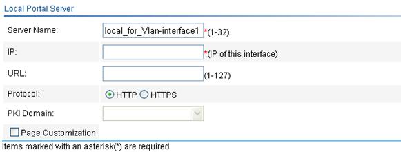
Figure 9 Local portal service configuration
|
Item |
Description |
|
|
Server Name |
Specify the local portal server name. |
|
|
IP |
Specify the IP address of the local portal server. You need to specify the IP address of the interface where the local portal server is applied. |
|
|
URL |
Specify the URL for HTTP packets redirection, in the format http://ip-address/portal/logon.htm or https://ip-address/portal/logon.htm (depending on the protocol type). By default, the IP address of the local portal server is used in the URL.
· To use the local portal server for stateful failover in a wireless environment, you must specify the redirection URL, and the IP address of the URL must be the virtual IP address of the VRRP group where the VRRP downlink resides. · URL redirection supports domain name resolution, but you need to configure a portal-free rule and add the DNS server address into the portal-free address range. |
|
|
Protocol |
Specify the protocol to be used for authentication information exchange between the local portal server and the client. It can be HTTP or HTTPS. |
|
|
PKI Domain |
Specify the PKI domain for HTTPS. This field is configurable when you select HTTPS. The available PKI domains are those specified on the page you enter by selecting Authentication > Certificate Management from the navigation tree. For more information, see "Managing certificates."
The service management, local portal authentication, and local EAP service modules always reference the same PKI domain. Changing the referenced PKI domain in any of the three modules will also change that referenced in the other two modules. |
|
|
Page Customization |
SSID |
Specify the authentication page files to be bound with SSIDs as required. After you bind SSIDs with authentication page files, when a user access the portal page, the local portal server pushes the authentication pages for the user according to the SSID of the user login interface and the bound authentication page file. By default, an SSID is not bound with any authentication page file. In this case, the system pushes the default authentication pages. You can edit an authentication page file as required and save it in the root directory or the portal directory under the root directory of the access device. For rules of customizing authentication pages, see "Customizing authentication pages." |
|
Page File |
||
Configuring advanced parameters for portal authentication
1. Select Authentication > Portal from the navigation tree.
2. Expand the Advanced area to show the advanced parameters for portal authentication.
Figure 10 Advanced configuration
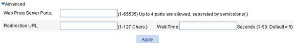
3. Configure the advanced parameters as described in Table 8.
4. Click Apply.
Table 8 Advanced portal parameters
|
Item |
Description |
|
Web Proxy Server Ports |
Add the web proxy server ports to allow HTTP requests proxied by the specified proxy servers to trigger portal authentication. By default, only HTTP requests that are not proxied can trigger portal authentication. Different clients may have different web proxy configurations. To make sure that clients using a web proxy can trigger portal authentication, you must first complete some other relevant configurations. When the IMC portal server is used, you must first complete the following configurations: · If the client does not specify the portal server's IP address as a proxy exception, ensure the IP connectivity between the portal server and the web proxy server and perform the following configurations on the IMC portal server: ¡ Select NAT as the type of the IP group associated with the portal device. ¡ Specify the proxy server's IP address as the IP address after NAT. ¡ Configure the port group to support NAT. · If the client specifies the portal server's IP address as an exception of the web proxy server, configure the IP group and port group to not support NAT.
· If a user's browser uses the Web Proxy Auto-Discovery (WPAD) protocol to discover web proxy servers, add the port numbers of the web proxy servers on the device, and configure portal-free rules to allow user packets destined for the IP address of the WPAD server to pass without authentication. · If the web proxy server port 80 is added on the device, clients that do not use a proxy server can trigger portal authentication only when they access a reachable host enabled with the HTTP service. Authorized ACLs to be assigned to users who have passed portal authentication must contain a rule that permits the web proxy server's IP address. Otherwise, the user cannot receive heartbeat packets from the remote portal server. |
|
Redirection URL |
Specify the auto redirection URL to which users will be automatically redirected after they pass portal authentication. To access the network, an unauthenticated user either goes to or is automatically forced to the portal authentication page for authentication. If the user passes portal authentication and the access device is configured with an auto redirection URL, the access device will redirect the user to the URL after a specified period of time. |
|
Wait-Time |
Period of time that the device must wait before redirecting an authenticated portal user to the auto redirection URL. |
Configuring a portal-free rule
1. Select Authentication > Portal from the navigation tree.
2. Click the Free Rule tab.
Figure 11 Portal-free rule configuration
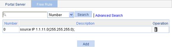
3. Click Add.
The page for adding a new portal-free rule appears.
Figure 12 Adding a portal-free rule
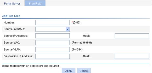
4. Configure the portal-free rule as described in Table 9.
5. Click Apply.
|
Item |
Description |
|
Number |
Specify the sequence number of the portal-free rule. |
|
Source-interface |
Specify the source interface of the portal-free rule. The SSIDs in the list are the corresponding SSIDs of the wireless ESS interfaces. |
|
Source IP address |
Specify the source IP address and mask of the portal-free rule. |
|
Mask |
|
|
Source MAC |
Specify the source MAC address of the portal-free rule.
If you configure both the source IP address and the source MAC address, make sure that the mask of the specified source IP address is 255.255.255.255. Otherwise, the specified source MAC address will not take effect. |
|
Source-VLAN |
Specify the source VLAN of the portal-free rule.
If you configure both a source interface and a source VLAN for a portal-free rule, make sure that the source interface is in the source VLAN. Otherwise, the portal-free rule will not take effect. |
|
Destination IP Address |
Specify the destination IP address and mask of the portal-free rule. |
|
Mask |
Customizing authentication pages
When the local portal server is used for portal authentication, the local portal server pushes authentication pages to users. You can customize the authentication pages. If you do not customize the authentication pages, the local portal server pushes the system default authentication pages to users.
Customized authentication pages exist in the form of HTML files. You can compress them and then upload them to the access device. A set of authentication pages include six main pages and some page elements. The six main pages are the logon page, the logon success page, the logon failure page, the online page, the system busy page, and the logoff success page. The page elements are the files that the authentication pages reference, for example, back.jpg for page Logon.htm. Each main authentication page can reference multiple page elements. If you define only some of the main pages, the local portal server pushes the system default authentication pages for the undefined ones to users.
For the local portal server to operate normally and steadily, you need to follow the following rules when customizing authentication pages:
Rules on file names
The main pages of the authentication pages have predefined file names, which cannot be changed.
Table 10 Main authentication page file names
|
Main authentication page |
File name |
|
Logon page |
logon.htm |
|
Logon success page |
logonSuccess.htm |
|
Logon failure page |
logonFail.htm |
|
Online page Pushed for online state notification |
online.htm |
|
System busy page Pushed when the system is busy or the user is in the logon process |
busy.htm |
|
Logoff success page |
logoffSuccess.htm |
|
|
NOTE: You can name the files other than the main page files. The file names and directory names are case insensitive. |
Rules on page requests
The local portal server supports only Post and Get requests.
· Get requests are used to get the static files in the authentication pages and allow no recursion. For example, if file Logon.htm includes contents that perform Get action on file ca.htm, file ca.htm cannot include any reference to file Logon.htm.
· Post requests are used when users submit usernames and passwords, log on to the system, and log off the system.
Rules on Post request attributes
1. Observe the following requirements when editing a form of an authentication page:
· An authentication page can have multiple forms, but there must be one and only one form whose action is logon.cgi. Otherwise, user information cannot be sent to the local portal server.
· The username attribute is fixed as PtUser, and the password attribute is fixed as PtPwd.
· Attribute PtButton is required to indicate the action that the user requests, which can be Logon or Logoff.
· A logon Post request must contain PtUser, PtPwd, and PtButton attributes.
· A logoff Post request must contain the PtButton attribute.
2. Authentication pages logon.htm and logonFail.htm must contain the logon Post request.
The following example shows part of the script in page logon.htm.
<form action=logon.cgi method = post >
<p>User name:<input type="text" name = "PtUser" style="width:160px;height:22px" maxlength=64>
<p>Password :<input type="password" name = "PtPwd" style="width:160px;height:22px" maxlength=32>
<p><input type=SUBMIT value="Logon" name = "PtButton" style="width:60px;" onclick="form.action=form.action+location.search;>
</form>
3. Authentication pages logonSuccess.htm and online.htm must contain the logoff Post request.
The following example shows part of the script in page online.htm.
<form action=logon.cgi method = post >
<p><input type=SUBMIT value="Logoff" name="PtButton" style="width:60px;">
</form>
Rules on page file compression and saving
· A set of authentication page files must be compressed into a standard zip file. The name of a zip file can contain only letters, digits, and underscores. The zip file of the default authentication pages must be saved with the name defaultfile.zip.
· The set of authentication pages must be located in the root directory of the zip file.
· Zip files can be transferred to the device through FTP or TFTP. The default authentication pages file must be saved in the root directory of the device, and customized authentication files can be saved in the root directory or in the portal directory under the root directory of the device.
Rules on file size and contents
For the system to push customized authentication pages smoothly, you need comply with the following size and content requirements on authentication pages.
· The size of the zip file of each set of authentication pages, including the main authentication pages and the page elements, must be no more than 500 KB.
· The size of a single page, including the main authentication page and the page elements, must be no more than 50 KB before being compressed.
· Page elements can contain only static contents such as HTML, JS, CSS, and pictures.
Logging off a user who closes the logon success or online page
After a user passes authentication, the system pushes the logon success page logonSuccess.htm to the user. If the user initiates another authentication through the logon page, the system pushes the online page online.htm. You can configure the device to forcibly log off the user when the user closes either of these two pages. To do so, add the following contents in logonSuccess.htm and online.htm:
1. Reference to file pt_private.js.
2. pt_unload(), the function for triggering page unloading.
3. pt_submit(), the event handler function for Form.
4. pt_init(), the function for triggering page loading.
The following is a script example with the added contents highlighted in gray:
<html>
<head>
<script type="text/javascript" language="javascript" src="pt_private.js"></script>
</head>
<body onload="pt_init();" onbeforeunload="return pt_unload();">
... ...
<form action=logon.cgi method = post onsubmit="pt_submit()">
... ...
</body>
</html>
Redirecting authenticated users to a specified web page
To make the device automatically redirect authenticated users to a specified web page, do the following in logon.htm and logonSuccess.htm:
1. In logon.htm, set the target attribute of the form object to blank.
See the contents in gray:
<form method=post action=logon.cgi target="blank">
2. Add the function for page loading pt_init() to logonSucceess.htm.
See the contents in gray:
<html>
<head>
<title>LogonSuccessed</title>
<script type="text/javascript" language="javascript" src="pt_private.js"></script>
</head>
<body onload="pt_init();" onbeforeunload="return pt_unload();">
... ...
</body>
</html>
|
|
NOTE: · H3C recommends using browser IE 6.0 or later on the authentication clients. · Make sure that the browser of an authentication client permits pop-ups or permits pop-ups from the access device. Otherwise, the user cannot log off by closing the logon success or online page and can only click Cancel to return to the logon success or online page. · If a user refreshes the logon success or online page, or jumps to another web site from either of the pages, the device also logs off the user. · If a user is using the Chrome browser, the device cannot log off the user when the user closes the logon success or online page. |
Portal authentication configuration example
Network requirements
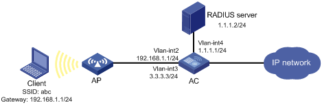
As shown in Figure 13, the wireless client belongs to VLAN 2. It accesses the network through the AP, which belongs to VLAN 3. The model and serial ID of the AP is WA2100 and 210235A29G007C00002, respectively.
AC supports the local portal server, which runs HTTPS. The local portal server can push the corresponding customized pages according to the SSID of the user logon interface.
A RADIUS server (IMC server) serves as the authentication/accounting server.
The client must pass direct portal authentication to access unrestricted Internet resources. Before authentication, the client can access only the local portal server.
Configuration prerequisites
Complete the follow tasks before you perform the portal configuration:
· Configure IP addresses for the devices as shown in Figure 13 and make sure they can reach each other.
· Configure PKI domain test, and make sure that a local certificate and a CA certificate are obtained successfully. For more information, see "Managing certificates."
· Complete the editing of the authentication page files to be bound with the client SSID.
· Configure the RADIUS server properly to provide authentication and accounting functions for users.
Configuring the AC
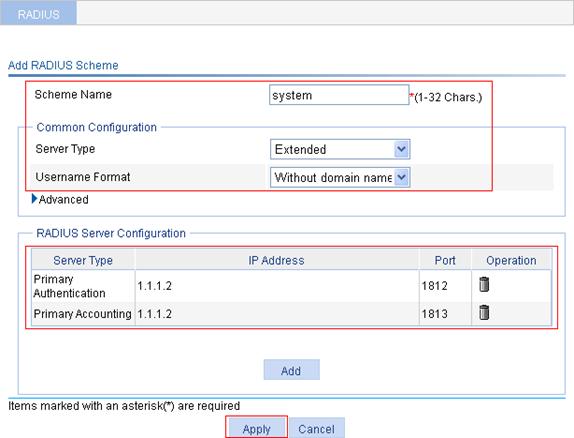
1. Configure the RADIUS scheme system:
a. From the navigation tree, select Authentication > RADIUS.
b. Click Add.
c. On the page that appears, enter the scheme name system, select the server type Extended, and select Without domain name for Username Format.
d. In the RADIUS Server Configuration area, click Add.
e. On the page that appears, select Primary Authentication as the server type, enter the IP address 1.1.1.2, the port number 1812, and the key expert, enter expert again in the Confirm Key field, and click Apply.
The RADIUS server configuration page closes, and the RADIUS Server Configuration area on the RADIUS scheme configuration page displays the authentication server you have just configured.
f. In the RADIUS Server Configuration area, click Add.
g. On the page that appears, select Primary Accounting as the server type, enter the IP address 1.1.1.2, the port number 1813, and the key expert, enter expert again in the Confirm Key field, and click Apply.
The RADIUS server configuration page closes, and the RADIUS Server Configuration area on the RADIUS scheme configuration page displays the accounting server you have just configured.
h. Click Apply.
Figure 14 Configuring the RADIUS scheme
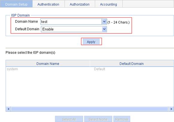
2. Create ISP domain test, and configure it as the default domain.
a. From the navigation tree, select Authentication > AAA.
The Domain Setup tab appears.
b. Enter the domain name test, and select Enable from the Default Domain list to use the domain test as the default domain.
c. Click Apply.
Figure 15 Creating an ISP domain
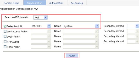
3. Configure an authentication method for the ISP domain.
a. Click the Authentication tab.
b. Select the domain name test.
c. Select the Default AuthN box and then select RADIUS as the authentication mode.
d. Select system from the Name list to use it as the authentication scheme
e. Click Apply.
A configuration progress dialog box appears.
f. After the configuration process is complete, click Close.
Figure 16 Configuring the authentication method for the ISP domain
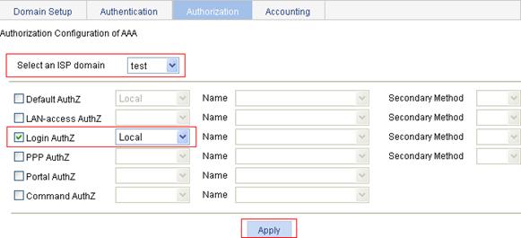
4. Configure an authorization method for the ISP domain.
a. Click the Authorization tab.
b. Select the Default AuthZ box and then select RADIUS as the authorization mode.
c. Select system from the Name list to use it as the authorization scheme
d. Click Apply.
A configuration progress dialog box appears
e. After the configuration process is complete, click Close.
Figure 17 Configuring the authorization method for the ISP domain

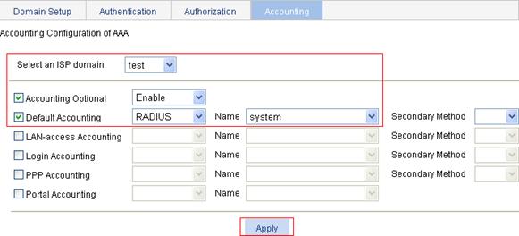
5. Configure an accounting method for the ISP domain.
a. Click the Accounting tab.
b. Select the domain name test.
c. Select the Accounting Optional box, and then select Enable for this parameter.
d. Select the Default Accounting box and then select RADIUS as the accounting mode.
e. Select system from the Name list to use it as the accounting scheme
f. Click Apply.
The configuration progress dialog box appears
g. After the configuration process is complete, click Close.
Figure 18 Configuring the accounting method for the ISP domain
6. Create an AP.
a. From the navigation tree, select AP > AP Setup.
b. Click Create.
c. Enter the AP name ap1.
d. Select model WA2100.
e. Select the manual mode for serial ID and then enter the serial ID 210235A29G007C00002.
f. Click Apply.
Figure 19 Creating an AP

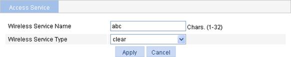
7. Create a wireless service.
a. From the navigation tree, select Wireless Service > Access Service.
b. Click New.
c. On the page that appears, enter the wireless service name abc, select clear as the wireless service type, and click Apply.
The wireless service configuration page appears.
Figure 20 Creating a wireless service
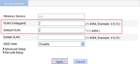
d. Enter 2 in the VLAN (Untagged) field, enter 2 in the Default VLAN field, and click Apply.
A configuration progress dialog box appears.
e. After the configuration process is complete, click Close.
Figure 21 Configuring parameters for the wireless service
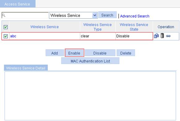
8. Enable the wireless service.
a. On wireless service list as shown in Figure 22, select the box before wireless service abc.
b. Click Enable.
A configuration progress dialog box appears.
c. After the configuration process is complete, click Close.
Figure 22 Enabling the wireless service
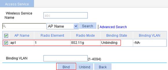
9. Bind an AP radio with the wireless service.
a. On the wireless service list, click the ![]() icon in the Operation column of wireless service abc.
icon in the Operation column of wireless service abc.
b. On the page that appears, select the box before ap1 with the radio mode of 802.11g.
c. Click Bind.
A configuration progress dialog box appears.
d. After the configuration process is complete, click Close.
Figure 23 Binding an AP radio
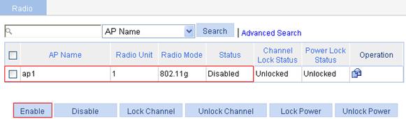
10. Enable radio.
a. From the navigation tree, select Radio > Radio.
b. Select the box before ap1 with the radio mode of 802.11g.
c. Click Enable.
Figure 24 Enabling 802.11g radio
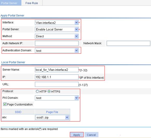
11. Configure portal authentication
a. From the navigation tree, select Authentication > Portal.
b. Click Add.
c. Select interface Vlan-interface2, select Enable Local Server for Portal Server, select Direct as the authentication method, select the authentication domain test, enter 192.168.1.1 as the server IP address, select HTTPS as the protocol type, select test as the PKI domain, select the box before Page Customization, and select the authentication page file ssid1.zip for SSID abc.
d. Click Apply.
Figure 25 Portal service application
12. Configure a portal-free rule for Ethernet port GigabitEthernet 1/0/1.
a. Click the Free Rule tab.
b. Click Add.
c. On the page that appears, enter the rule number 0, and select the source interface GigabitEthernet1/0/1.
d. Click Apply.
Verifying the configuration
When a user accesses subnet 1.1.1.0/24, the user is redirected to page https://192.168.1.1/portal/logon.htm and, after entering the correct username and password on the web page, the user passes the authentication.
AAA overview
Authentication, Authorization, and Accounting (AAA) provides a uniform framework for implementing network access management. It provides the following security functions:
· Authentication—Identifies users and determines whether a user is valid.
· Authorization—Grants different users different rights and controls their access to resources and services. For example, a user who has successfully logged in to the device can be granted read and print permissions to the files on the device.
· Accounting—Records all network service usage information of users, including the service type, start time, and traffic. The accounting function not only provides the information required for charging, but also allows for network security surveillance.
AAA usually uses a client/server model. The client runs on the network access server (NAS) and the server maintains user information centrally. In an AAA network, a NAS is a server for users but a client for the AAA servers.
Figure 26 Network diagram for AAA
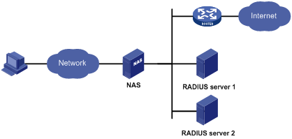
AAA can be implemented through multiple protocols. The device supports using RADIUS, the most commonly used protocol in practice. For more information about RADIUS, see "Configuring RADIUS." For more information about AAA and ISP, see H3C WA Series WLAN Access Points Security Configuration Guide.
Configuring AAA
Configuration prerequisites
· To deploy local authentication, configure local users on the access device as described in "Configuring users."
· To deploy remote authentication, authorization, or accounting, create the RADIUS schemes to be referenced as described in "Configuring RADIUS."
Recommended configuration procedure
|
Step |
Remarks |
|
|
Optional. Create ISP domains and specify one of them as the default ISP domain. By default, there is an ISP domain named system, which is the default ISP domain. |
||
|
Optional. Configure authentication methods for various types of users. By default, all types of users use local authentication. |
AAA user types include LAN access users (such as 802.1x authentication users and MAC authentication users), login users (such as SSH, Telnet, FTP, terminal access users), PPP users, Portal users, and Command users. |
|
|
Optional. Specify the authorization methods for various types of users. |
||
|
Required. Specify the accounting methods for various types of users. By default, all types of users use local accounting. |
||
Configuring an ISP domain
1. Select Authentication > AAA from the navigation tree.
The Domain Setup page appears.
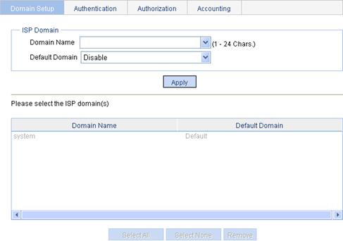
2. Configure an ISP domain as described in Table 11.
3. Click Apply.
|
Item |
Description |
|
Domain Name |
Enter the ISP domain name, which is for identifying the domain. You can enter a new domain name to create a domain, or specify an existing domain to change its status (whether it is the default domain). |
|
Default Domain |
Specify whether to use the ISP domain as the default domain. Options include: · Enable—Uses the domain as the default domain. · Disable—Uses the domain as a non-default domain. There can only be one default domain at a time. If you specify a second domain as the default domain, the original default domain will become a non-default domain. |
Configuring authentication methods for the ISP domain
1. Select Authentication > AAA from the navigation tree.
2. Click the Authentication tab to enter the authentication method configuration page.
Figure 28 Authentication method configuration page
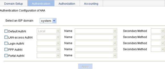
3. Configure authentication methods for different types of users in the domain, as described in Table 12.
4. Click Apply.
A configuration progress dialog box appears.
5. After the configuration progress is complete, click Close.
|
Item |
Description |
|
Select an ISP domain |
Select the ISP domain for which you want to specify authentication methods. |
|
Default AuthN |
Configure the default authentication method and secondary authentication method for all types of users. Options include: · HWTACACS—Performs HWTACACS authentication. You must specify the HWTACACS scheme to be used. · Local—Performs local authentication. · None—All users are trusted and no authentication is performed. Generally, do not use this mode. · RADIUS—Performs RADIUS authentication. You must specify the RADIUS scheme to be used. · Not Set—Restore the default, that is, local authentication. |
|
Name |
|
|
Secondary Method |
|
|
LAN-access AuthN |
Configure the authentication method and secondary authentication method for LAN access users. Options include: · Local—Performs local authentication. · None—All users are trusted and no authentication is performed. Generally, do not use this mode. · RADIUS—Performs RADIUS authentication. You must specify the RADIUS scheme to be used. · Not Set—Uses the default authentication methods. |
|
Name |
|
|
Secondary Method |
|
|
Login AuthN |
Configure the authentication method and secondary authentication method for login users. Options include: · HWTACACS—Performs HWTACACS authentication. You must specify the HWTACACS scheme to be used. · Local—Performs local authentication. · None—All users are trusted and no authentication is performed. Generally, do not use this mode. · RADIUS—Performs RADIUS authentication. You must specify the RADIUS scheme to be used. · Not Set—Uses the default authentication methods. |
|
Name |
|
|
Secondary Method |
|
|
PPP AuthN |
Configure the authentication method and secondary authentication method for PPP users. Options include: · HWTACACS—Performs HWTACACS authentication. You must specify the HWTACACS scheme to be used. · Local—Performs local authentication. · None—All users are trusted and no authentication is performed. Generally, do not use this mode. · RADIUS—Performs RADIUS authentication. You must specify the RADIUS scheme to be used. · Not Set—Uses the default authentication methods. |
|
Name |
|
|
Secondary Method |
|
|
Portal AuthN |
Configure the authentication method for Portal users. Options include: · Local—Performs local authentication. · None—All users are trusted and no authentication is performed. Generally, do not use this mode. · RADIUS—Performs RADIUS authentication. You must specify the RADIUS scheme to be used. · Not Set—Uses the default authentication methods. |
|
Name |
Configuring authorization methods for the ISP domain
1. Select Authentication > AAA from the navigation tree.
2. Click the Authorization tab to enter the authorization method configuration page.
Figure 29 Authorization method configuration page
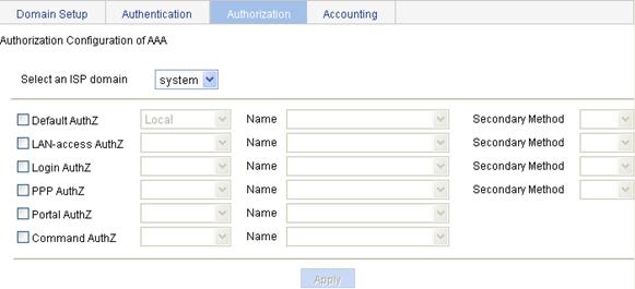
3. Configure authorization methods for different types of users in the domain, as described in Table 13.
4. Click Apply.
A configuration progress dialog box appears.
5. After the configuration progress is complete, click Close.
|
Item |
Description |
|
Select an ISP domain |
Select the ISP domain for which you want to specify authentication methods. |
|
Default AuthZ |
Configure the default authorization method and secondary authorization method for all types of users. Options include: · HWTACACS—Performs HWTACACS authorization. You must specify the HWTACACS scheme to be used. · Local—Performs local authorization. · None—All users are trusted and authorized. A user gets the default rights of the system. · RADIUS—Performs RADIUS authorization. You must specify the RADIUS scheme to be used. · Not Set—Restore the default, that is, local authorization. |
|
Name |
|
|
Secondary Method |
|
|
LAN-access AuthZ |
Configure the authorization method and secondary authorization method for LAN access users. Options include: · Local—Performs local authorization. · None—All users are trusted and authorized. A user gets the default rights of the system. · RADIUS—Performs RADIUS authorization. You must specify the RADIUS scheme to be used. · Not Set—Uses the default authorization methods. |
|
Name |
|
|
Secondary Method |
|
|
Login AuthZ |
Configure the authorization method and secondary authorization method for login users. Options include: · HWTACACS—Performs HWTACACS authorization. You must specify the HWTACACS scheme to be used. · Local—Performs local authorization. · None—All users are trusted and authorized. A user gets the default rights of the system. · RADIUS—Performs RADIUS authorization. You must specify the RADIUS scheme to be used. · Not Set—Uses the default authorization methods. |
|
Name |
|
|
Secondary Method |
|
|
PPP AuthZ |
Configure the authorization method and secondary authorization method for PPP users. Options include: · HWTACACS—Performs HWTACACS authorization. You must specify the HWTACACS scheme to be used. · Local—Performs local authorization. · None—All users are trusted and authorized. A user gets the default rights of the system. · RADIUS—Performs RADIUS authorization. You must specify the RADIUS scheme to be used. · Not Set—Uses the default authorization methods. |
|
Name |
|
|
Secondary Method |
|
|
Portal AuthZ |
Configure the authorization method for Portal users. Options include: · Local—Performs local authorization. · None—All users are trusted and authorized. A user gets the default rights of the system. · RADIUS—Performs RADIUS authorization. You must specify the RADIUS scheme to be used. · Not Set—Uses the default authorization methods. |
|
Name |
|
|
Command AuthZ |
Configure the authorization method for command users. Options include: · HWTACACS—Performs HWTACACS authorization. You must specify the HWTACACS scheme to be used. · Not Set—Uses the default authorization methods. |
|
Name |
Configuring accounting methods for the ISP domain
1. Select Authentication > AAA from the navigation tree.
2. Click the Accounting tab to enter the accounting method configuration page.
Figure 30 Accounting method configuration page
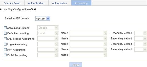
3. Configure accounting methods for different types of users in the domain, as described in Table 14.
4. Click Apply.
A configuration progress dialog box appears.
5. After the configuration progress is complete, click Close.
|
Item |
Description |
|
Select an ISP domain |
Select the ISP domain for which you want to specify authentication methods. |
|
Accounting Optional |
Specify whether to enable the accounting optional feature. With the feature enabled, a user that will be disconnected otherwise can use the network resources even when there is no accounting server available or communication with the current accounting server fails. If accounting for such a user fails, the device will not send real-time accounting updates for the user anymore. |
|
Default Accounting |
Configure the default accounting method and secondary accounting method for all types of users. Options include: · HWTACACS—Performs HWTACACS accounting. You must specify the HWTACACS scheme to be used. · Local—Performs local accounting. · None—Performs no accounting. · RADIUS—Performs RADIUS accounting. You must specify the RADIUS scheme to be used. · Not Set—Restore the default, that is, local accounting. |
|
Name |
|
|
Secondary Method |
|
|
LAN-access Accounting |
Configure the accounting method and secondary accounting method for LAN access users. Options include: · Local—Performs local accounting. · None—Performs no accounting. · RADIUS—Performs RADIUS accounting. You must specify the RADIUS scheme to be used. · Not Set—Uses the default accounting methods. |
|
Name |
|
|
Secondary Method |
|
|
Login Accounting |
Configure the accounting method and secondary accounting method for login users. Options include: · HWTACACS—Performs HWTACACS accounting. You must specify the HWTACACS scheme to be used. · Local—Performs local accounting. · None—Performs no accounting. · RADIUS—Performs RADIUS accounting. You must specify the RADIUS scheme to be used. · Not Set—Uses the default accounting methods. |
|
Name |
|
|
Secondary Method |
|
|
PPP Accounting |
Configure the accounting method and secondary accounting method for PPP users. Options include: · HWTACACS—Performs HWTACACS accounting. You must specify the HWTACACS scheme to be used. · Local—Performs local accounting. · None—Performs no accounting. · RADIUS—Performs RADIUS accounting. You must specify the RADIUS scheme to be used. · Not Set—Uses the default accounting methods. |
|
Name |
|
|
Secondary Method |
|
|
Portal Accounting |
Configure the accounting method for Portal users. Options include: · Local—Performs local accounting. · None—Performs no accounting. · RADIUS—Performs RADIUS accounting. You must specify the RADIUS scheme to be used. · Not Set—Uses the default accounting methods. |
|
Name |
AAA configuration example
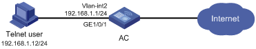
Network requirements
As shown in Figure 31, configure the AC to perform local authentication, authorization, and accounting for Telnet users.
Configuration procedure
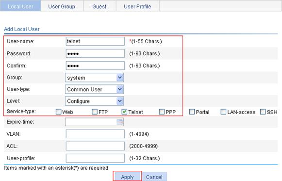
1. Configure a local user:
a. Select Authentication > Users from the navigation tree.
The local user management page appears.
b. Click Add.
c. Enter telnet the username.
d. Enter abcd as the password.
e. Enter abcd again to confirm the password.
f. Select Common User as the user type.
g. Select Configure as the level.
h. Select Telnet as the service type.
i. Click Apply.
Figure 32 Configuring the local user
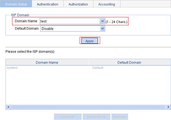
2. Configure ISP domain test.
a. Select Authentication > AAA from the navigation tree.
The Domain Setup page appears, as shown in Figure 33.
b. Enter test as the domain name.
c. Click Apply.
Figure 33 Configuring ISP domain test
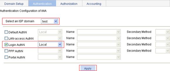
3. Configure the ISP domain to use local authentication for login users:
a. Select Authentication > AAA from the navigation tree
b. Click the Authentication tab.
c. Select the domain test.
d. Select the Login AuthN box and select the authentication method Local.
e. Click Apply.
A configuration progress dialog box appears.
f. After the configuration progress is complete, click Close.
Figure 34 Configuring the ISP domain to use local authentication
4. Configure the ISP domain to use local authorization for login users:
a. Select Authentication > AAA from the navigation tree.
b. Click the Authorization tab.
c. Select the domain test.
d. Select the Login AuthZ box and select the authorization method Local.
e. Click Apply.
A configuration progress dialog box appears.
f. After the configuration progress is complete, click Close.
Figure 35 Configuring the ISP domain to use local authorization
5. Log in to the CLI, enable Telnet service, and configure the AC to use AAA for Telnet users.
<AC> system-view
[AC] telnet server enable
[AC] user-interface vty 0 4
[AC-ui-vty0-4] authentication-mode scheme
[AC-ui-vty0-4] quit
6. Verify the configuration
Telnet to the AC and enter the username telnet@test and password abcd. You should be serviced as a user in domain test.
RADIUS overview
The Remote Authentication Dial-In User Service (RADIUS) protocol implements Authentication, Authorization, and Accounting (AAA). RADIUS uses the client/server model. It can protect networks against unauthorized access and is often used in network environments where both high security and remote user access are required. RADIUS defines the packet format and message transfer mechanism, and uses UDP as the transport layer protocol for encapsulating RADIUS packets. It uses UDP port 1812 for authentication and UDP port 1813 for accounting.
RADIUS was originally designed for dial-in user access. With the addition of new access methods, RADIUS has been extended to support additional access methods, for example, Ethernet and ADSL. RADIUS provides access authentication and authorization services, and its accounting function collects and records network resource usage information.
For more information about AAA and RADIUS, see H3C WA Series WLAN Access Points Security Configuration Guide.
Configuring a RADIUS scheme
To configure a RADIUS scheme:
1. Select Authentication > RADIUS from the navigation tree.
Figure 36 RADIUS scheme list
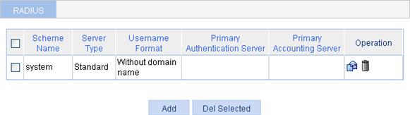
2. Click Add.
Figure 37 RADIUS scheme configuration page
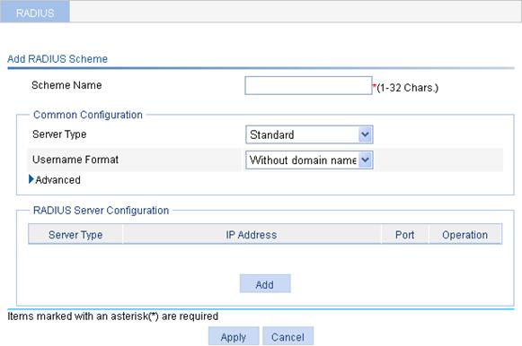
3. Enter a scheme name.
4. Select a server type and a username format.
|
Item |
Description |
|
Server Type |
Select the type of the RADIUS servers supported by the device, which can be: · Standard—Specifies the standard RADIUS server. That is, the RADIUS client and RADIUS server communicate by using the standard RADIUS protocol and packet format defined in RFC 2865/2866 or later. · Extended—Specifies an extended RADIUS server (usually running on IMC). In this case, the RADIUS client and the RADIUS server communicate by using the proprietary RADIUS protocol and packet format. |
|
Username Format |
Select the format of usernames to be sent to the RADIUS server. A username is generally in the format of userid@isp-name, of which isp-name is used by the device to determine the ISP domain to which a user belongs. If a RADIUS server (such as a RADIUS server of some early version) does not accept a username that contains an ISP domain name, you can configure the device to remove the domain name of a username before sending it to the RADIUS server. · Original format—Sends the username of a user on an "as is" basis. · With domain name—Includes the domain name in a username to be sent to the RADIUS server. · Without domain name—Removes the domain name of a username to be sent to the RADIUS server. |
5. Click the expand button before Advanced in the Common Configuration area to expand the advanced configuration area.
Figure 38 Common configuration area
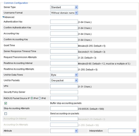
6. Configure the advanced parameters.
Table 16 Configuration items
|
Item |
Description |
|
|
Authentication Key |
Set the shared key for RADIUS authentication packets and that for RADIUS accounting packets. The RADIUS client and the RADIUS authentication/accounting server use MD5 to encrypt RADIUS packets, and they verify the validity of packets through the specified shared key. Only if the shared key of the client and that of the server are the same, will the client and the server receive and respond to packets from each other.
· The shared keys configured on the device must be consistent with those configured on the RADIUS servers. · The shared keys configured in the common configuration part are used only when no corresponding shared keys are configured in the RADIUS server configuration part. |
|
|
Confirm Authentication Key |
||
|
Accounting Key |
||
|
Confirm Accounting Key |
||
|
Quiet Time |
Set the time the device keeps an unreachable RADIUS server in blocked state. If you set the quiet time to 0, when the device needs to send an authentication or accounting request but finds that the current server is unreachable, it does not change the server's status that it maintains. It simply sends the request to the next server in active state. As a result, when the device needs to send a request of the same type for another user, it still tries to send the request to the server because the server is in active state. You can use this parameter to control whether the device changes the status of an unreachable server. For example, if you determine that the primary server is unreachable because the device's port for connecting the server is out of service temporarily or the server is busy, you can set the time to 0 so that the device uses the primary server as much. |
|
|
Server Response Timeout Time |
Set the RADIUS server response timeout time. If the device sends a RADIUS request to a RADIUS server but receives no response within the specified server response timeout time, it retransmits the request. Setting a proper value according to the network conditions helps in improving the system performance. |
The server response timeout time multiplied by the maximum number of RADIUS packet transmission attempts must not exceed 75. |
|
Request Transmission Attempts |
Set the maximum number of attempts for transmitting a RADIUS packet to a single RADIUS server. If the device does not receive a response to its request from the RADIUS server within the response timeout period, it retransmits the RADIUS request. If the number of transmission attempts exceeds the limit but the device still receives no response from the RADIUS server, the device considers the request a failure. |
|
|
Realtime Accounting Interval |
Set the interval for sending real-time accounting information. The interval must be a multiple of 3. To implement real-time accounting, the device must send real-time accounting packets to the accounting server for online users periodically. Different real-time accounting intervals impose different performance requirements on the NAS and the RADIUS server. A shorter interval helps achieve higher accounting precision but requires higher performance. Use a longer interval when a large number of users (1000 or more) exist. For more information about the recommended real-time accounting intervals, see "Configuration guidelines." |
|
|
Realtime Accounting Attempts |
Set the maximum number of attempts for sending a real-time accounting request. |
|
|
Unit for Data Flows |
Specify the unit for data flows sent to the RADIUS server, which can be byte, kilo-byte, mega-byte, or giga-byte. |
|
|
Unit for Packets |
Specify the unit for data packets sent to the RADIUS server, which can be: · One-packet. · Kilo-packet. · Mega-packet. · Giga-packet. |
|
|
Enable EAP offload |
Enable or disable the EAP offload function. Some RADIUS servers do not support EAP authentication. They cannot process EAP packets. In this case, it is necessary to preprocess the EAP packets received from clients on the access device. This is where the EAP offload function comes in. After receiving an EAP packet, the access device enabled with the EAP offload function first converts the authentication information in the EAP packet into the corresponding RADIUS attributes through the local EAP server, encapsulates the EAP packet into a RADIUS request and then sends the request to the RADIUS server for authentication. When the RADIUS server receives the request, it analyzes the carried authentication information, encapsulates the authentication result in a RADIUS packet, and then sends the packet to the local EAP server on the access device for subsequent interaction with the client. |
|
|
Security Policy Server |
Specify the IP address of the security policy server. |
|
|
RADIUS Packet Source IP |
Specify the source IP address for the device to use in RADIUS packets sent to the RADIUS server. H3C recommends you to use a loopback interface address instead of a physical interface address as the source IP address, because if the physical interface is down, the response packets from the server cannot reach the device. |
|
|
RADIUS Packet Backup Source IP |
Specify the backup source IP address for the device to use in RADIUS packets sent to the RADIUS server. In a stateful failover environment, the backup source IP address must be the source IP address for the remote device to use in RADIUS packets sent to the RADIUS server. Configuring the backup source IP address in a stateful failover environment makes sure that the backup server can receive the RADIUS packets sent from the RADIUS server when the master device fails. |
|
|
Buffer stop-accounting packets |
Enable or disable buffering of stop-accounting requests for which no responses are received. |
|
|
Stop-Accounting Attempts |
Set the maximum number of stop-accounting attempts. The maximum number of stop-accounting attempts, together with some other parameters, controls how the NAS deals with stop-accounting request packets. Suppose that the RADIUS server response timeout period is three seconds, the maximum number of transmission attempts is five, and the maximum number of stop-accounting attempts is 20. For each stop-accounting request, if the device receives no response within three seconds, it retransmits the request. If it receives no responses after retransmitting the request five times, it considers the stop-accounting attempt a failure, buffers the request, and makes another stop-accounting attempt. If 20 consecutive attempts fail, the device discards the request. |
|
|
Send accounting-on packets |
Enable or disable the accounting-on feature. The accounting-on feature enables a device to send accounting-on packets to RADIUS servers after it reboots, making the servers forcedly log out users who logged in through the device before the reboot.
When enabling the accounting-on feature on a device for the first time, you must save the configuration so that the feature takes effect after the device reboots. |
|
|
Accounting-On Interval |
Set the interval for sending accounting-on packets. This field is configurable only when the Send accounting-on packets option is selected. |
|
|
Accounting-On Attempts |
Set the maximum number of accounting-on packets transmission attempts. This field is configurable only when the Send accounting-on packets option is selected. |
|
|
Attribute |
Enable or disable the device to interpret the RADIUS class attribute as CAR parameters. |
|
|
Interpretation |
||
7. In the RADIUS Server Configuration area, click Add to enter the RADIUS server configuration page.
Figure 39 RADIUS server configuration page
8. Configure a RADIUS server for the RADIUS scheme as described in Table 17.
9. Click Apply to add the server to the RADIUS scheme.
10. Repeat step 7 through step 9 to add more RADIUS servers to the RADIUS scheme.
11. On the RADIUS scheme configuration page, click Apply.
|
Item |
Description |
|
Server Type |
Select the type of the RADIUS server to be configured. Possible values include primary authentication server, primary accounting server, secondary authentication server, and secondary accounting server. |
|
IP Address |
Specify the IP address of the RADIUS server. |
|
Port |
Specify the UDP port of the RADIUS server. |
|
Key |
Specify the shared key for communication with the RADIUS server. If no shared key is specified here, the shared key specified in the common configuration part is used. |
|
Confirm Key |
RADIUS configuration example
Network requirements
As shown in Figure 40, a RADIUS server running on IMC uses UDP ports 1812 and 1813 to provide authentication and accounting services respectively.
Configure the AC to use the RADIUS server for Telnet user authentication and accounting, and to remove domain names from the usernames sent to the server.
On the RADIUS server, configure a Telnet user account with the username hello@bbb and the password abc, and set the EXEC privilege level to 3 for the user.
Set the shared keys for packet exchange between the AC and the RADIUS server to expert.

Configuration procedure
1. Configure RADIUS scheme system:
a. Select Authentication > RADIUS from the navigation tree.
b. Click Add.
c. Enter the scheme name system, select the server type Extended, and select the username format Without domain name.
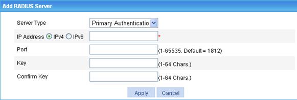
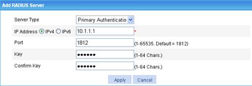
d. In the RADIUS Server Configuration area, click Add to enter the RADIUS server configuration page.
e. Select the server type Primary Authentication, enter 10.1.1.1 as the IP address of the primary authentication server, 1812 as the port number, and expert as the key, and click Apply to add the primary authentication server to the scheme.
Figure 41 RADIUS authentication server configuration page
f. In the RADIUS Server Configuration area, click Add to enter the RADIUS server configuration page again.
g. Select Primary Accounting as the server type, enter 10.1.1.1 as the IP address of the primary accounting server, enter the port number 1813, the key expert, and click Apply, as shown in Figure 42.
The RADIUS scheme configuration page refreshes and the added servers appear in the server list, as shown in Figure 43.
h. Click Apply to finish the scheme configuration.
Figure 42 RADIUS accounting server configuration page
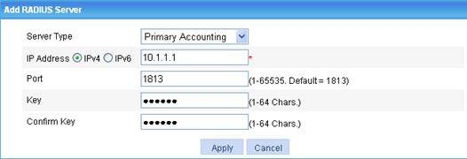
Figure 43 RADIUS scheme configuration
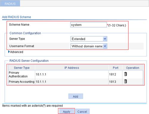
2. Create an ISP domain:
a. From the navigation tree, select Authentication > AAA.
The domain setup page appears.
b. Enter bbb in the Domain Name box.
c. Click Apply.
Figure 44 Creating an ISP domain
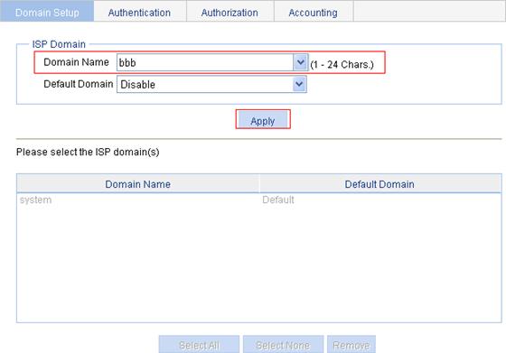
3. Configure an authentication method for the ISP domain:
a. Click the Authentication tab.
b. Select the domain name bbb.
c. Select the Default AuthN box and then select the authentication mode RADIUS.
d. Select the RADIUS scheme system from the Name list to use it as the authentication scheme.
e. Click Apply.
A configuration progress dialog box appears.
f. After the configuration progress is complete, click Close.
Figure 45 Configuring an authentication method for the ISP domain
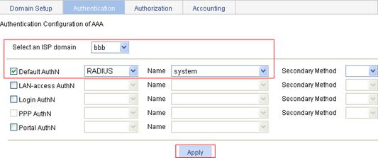
4. Configure an authorization method for the ISP domain:
a. Click the Authorization tab.
b. Select the domain name bbb.
c. Select the Default AuthZ box and select the authorization mode RADIUS.
d. Select the RADIUS scheme system from the Name list to use it as the authorization scheme.
e. Click Apply.
A configuration progress dialog box appears.
f. After the configuration progress is complete, click Close.
Figure 46 Configuring an authorization method for the ISP domain
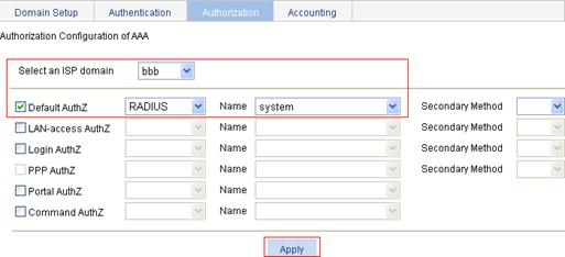
5. Configure an accounting method for the ISP domain, and enable accounting optional:
a. Click the Accounting tab.
b. Select the domain name bbb.
c. Select the Accounting Optional box and then select Enable.
d. Select the Default Accounting box and then select accounting mode RADIUS.
e. Select the RADIUS scheme system from the Name list to use it as the accounting scheme.
f. Click Apply.
A configuration progress dialog box appears.
g. After the configuration progress is complete, click Close.
Figure 47 Configuring an accounting method for the ISP domain
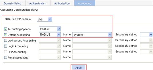
6. Enable the Telnet service.
a. From the navigation tree, select Network > Service.
b. Select the Enable Telnet service box.
c. Click Apply.
Figure 48 Enabling the Telnet service
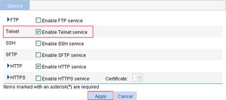
7. Log in to the CLI, and configure the VTY user interfaces to use AAA for user access control.
<AC> system-view
[AC] user-interface vty 0 4
[AC-ui-vty0-4] authentication-mode scheme
[AC-ui-vty0-4] quit
Verifying the configuration
Telnet to the AC and enter the username hello@bbb and password abc. You can log in and access commands of levels 0 through 3.
Configuration guidelines
When you configure the RADIUS client, follow these guidelines:
· Accounting for FTP users is not supported.
· If you remove the accounting server used for online users, the device cannot send real-time accounting requests and stop-accounting messages for the users to the server, and the stop-accounting messages are not buffered locally.
· The status of RADIUS servers (blocked or active) determines which servers the device will communicate with or turn to when the current servers are not available. In practice, you can specify one primary RADIUS server and multiple secondary RADIUS servers, with the secondary servers that function as the backup of the primary servers. Generally, the device chooses servers based on these rules:
¡ When the primary server is in active state, the device communicates with the primary server. If the primary server fails, the device changes the state of the primary server to blocked, starts a quiet timer for the server, and turns to a secondary server in active state (a secondary server configured earlier has a higher priority). If the secondary server is unreachable, the device changes the state of the secondary server to blocked, starts a quiet timer for the server, and continues to check the next secondary server in active state. This search process continues until the device finds an available secondary server or has checked all secondary servers in active state. If the quiet timer of a server expires or an authentication or accounting response is received from the server, the status of the server changes back to active automatically, but the device does not check the server again during the authentication or accounting process. If no server is found reachable during one search process, the device considers the authentication or accounting attempt a failure.
¡ Once the accounting process of a user starts, the device keeps sending the user's real-time accounting requests and stop-accounting requests to the same accounting server. If you remove the accounting server, real-time accounting requests and stop-accounting requests for the user cannot be delivered to the server any more.
¡ If you remove an authentication or accounting server in use, the communication of the device with the server will soon time out, and the device will look for a server in active state from scratch: it checks the primary server (if any) first and then the secondary servers in the order they are configured.
¡ When the primary server and secondary servers are all in blocked state, the device communicates with the primary server. If the primary server is available, its statues changes to active. Otherwise, its status remains to be blocked.
¡ If one server is in active state but all the others are in blocked state, the device only tries to communicate with the server in active state, even if the server is unavailable.
¡ After receiving an authentication/accounting response from a server, the device changes the status of the server identified by the source IP address of the response to active if the current status of the server is blocked.
· It is a good practice to use the recommended real-time accounting intervals listed in Table 18.
Table 18 Recommended real-time accounting intervals
|
Number of users |
Real-time accounting interval (in minutes) |
|
1 to 99 |
3 |
|
100 to 499 |
6 |
|
500 to 999 |
12 |
|
≥1000 |
≥15 |
In some simple application environments, you may want to use an access device to authenticate users locally, instead of deploying AAA servers for user authentication. When the Extensible Authentication Protocol (EAP) is used for user authentication, configure the local EAP authentication server to cooperate with local authentication method of AAA for local EAP authentication. For more information about AAA, see "Configuring AAA."
Configuration procedure
1. Select Authentication > Local EAP Server from the navigation.
The Local EAP service configuration page appears.
Figure 49 Local EAP service configuration page
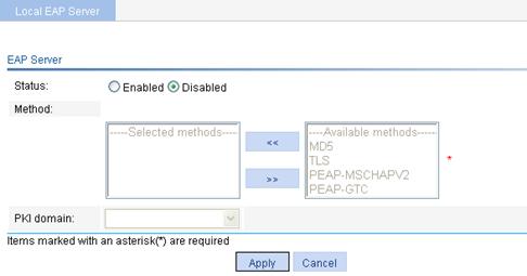
2. Configure the local EAP service as described in Table 19.
3. Click Apply.
|
Item |
Description |
|
Status |
Enable or disable the EAP server. If the EAP server is enabled, the EAP authentication method and PKI domain configurations are required. |
|
Method |
Specify the EAP authentication methods, including: · MD5—Uses Message Digest 5 (MD5) for authentication. · TLS—Uses the Transport Layer Security (TLS) protocol for authentication. · PEAP-MSCHAPV2—Uses the Protected Extensible Authentication Protocol (PEAP) for authentication and uses the Microsoft Challenge Handshake Authentication Protocol version 2 (MSCHAPv2) for authentication in the established TLS tunnel. · PEAP-GTC—Uses the Protected Extensible Authentication Protocol (PEAP) for authentication and uses the Microsoft Generic Token Card (GTC) for authentication in the established TLS tunnel. When an EAP client and the local server communicate for EAP authentication, they first negotiate the EAP authentication method to be used. During negotiation, the local server prefers the authentication method with the highest priority from the EAP authentication method list. If the client supports the authentication method, the negotiation succeeds and they proceed with the authentication process. Otherwise, the local server tries the one with the next highest priority until a supported one is found, or if none of the authentication methods are found supported, the local server sends an EAP-Failure packet to the client for notification of the authentication failure.
· You can select more than one authentication method. An authentication method selected earlier has a higher priority. · PEAP-MSCHAPV2 and PEAP-GTC are mutually exclusive. |
|
PKI domain |
Specify the PKI domain for EAP authentication. The available PKI domains are those configured on the page you enter by selecting Authentication > Certificate Management. For more information, see "Managing certificates." NOTE: The service management, local portal authentication, and local EAP service modules always reference the same PKI domain. Changing the referenced PKI domain in any of the three modules will also change that referenced in the other two modules. |
Local EAP service configuration example
Network requirements
As shown in Figure 50, configure the AC to perform local EAP authentication and authorization for 802.1X users by using the authentication method EAP-TLS.
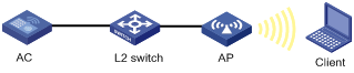
Configuration procedure
|
|
NOTE: · To implement local EAP authentication and authorization for 802.1X users, make sure that port security is enabled and 802.1X authentication uses the EAP authentication mode. · To use the authentication method of EAP-TLS, configure the network properties of the connection and the client certificate properly on the client. · For more information about how to configure PKI domain test, requesting a local certificate, and retrieving a CA certificate, see "Managing certificates." |
1. Configure local user usera:
a. Select Authentication > Users from the navigation tree.
b. Click Add.
c. Enter the username usera and password 1234, and select the service type LAN-Access.
d. Click Apply.
Figure 51 Local user configuration page
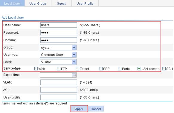
2. Configure the ISP domain system to use local authentication and local authorization.
The ISP domain system uses local authentication and local authorization by default. For the configuration procedure, see "Configuring AAA."
3. Enable the EAP server, configure the authentication method as TLS, and the PKI domain as test:
a. Select Authentication > Local EAP Server from the navigation tree.
b. Select Enabled for Status.
c. Select TLS from the Available methods list and click << to add TLS to the Selected methods list.
d. Select test from the PKI domain list.
e. Click Apply.
Figure 52 Configuring a local EAP server
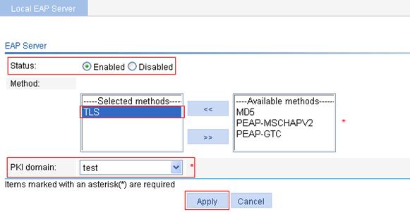
4. Configure the AP:
a. Select AP > AP Setup from the navigation tree.
b. Click Add.
c. Enter the AP name ap1.
d. Select the device model WA2620-AGN.
e. Select manual and enter the serial number in the following box.
f. Click Apply.
Figure 53 Configuring the AP
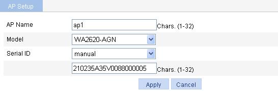
5. Create the wireless service:
a. Select Wireless Service > Access Service from the navigation tree.
b. Click Add.
c. Enter the wireless service name 802.1x-auth.
d. Select the service type crypto.
e. Click Apply.
The wireless service configuration page appears.
Figure 54 Creating a wireless service
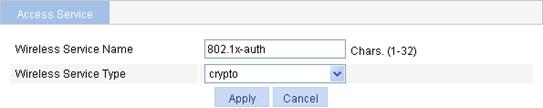
6. Configure the wireless service:
a. Click the expand button before Security Setup to expand the configuration items.
b. Select the authentication type Open-System.
c. Select the Cipher Suite box, and then select AES-CCMP and TKIP (select a cipher suite according to your actual network requirements). Select WPA as the security IE.
d. Click the expand button before Port Security to expand the configuration items.
e. Select the Port Set box and Select the port mode userlogin-secure-ext.
f. Select the Mandatory Domain box, and then select system.
g. Select the authentication method EAP.
h. Disable handshake and multicast trigger.
i. Click Apply.
A configuration progress dialog box appears.
j. When a dialog box appears asking for your confirmation to enable the EAP service, confirm the operation to proceed.
k. After the configuration process is complete, click Close.
Figure 55 Wireless service configuration page
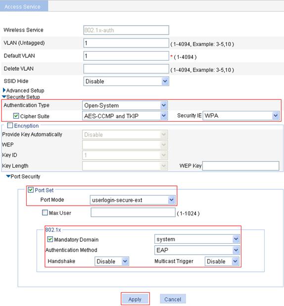
7. Enable the wireless service:
a. On the access service list page, select the wireless service 802.1x-auth.
b. Click Enable.
A progress dialog box appears.
c. After the configuration process is complete, click Close.
Figure 56 Enabling the wireless service
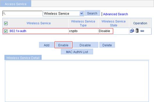
8. Bind the AP's radio mode with the wireless service:
a. In the wireless service list, click the ![]() icon of wireless service 802.1x-auth.
icon of wireless service 802.1x-auth.
b. Select the AP of ap1 with the radio mode 802.11n(2.4GHz).
c. Click Bind. A progress dialog box appears.
d. After the configuration process is complete, click Close.
Figure 57 Binding the radio mode with the wireless service

9. Enable 802.11n(2.4GHz).
a. Select Radio > Radio from the navigation tree.
b. Select the AP of ap1 with the radio mode 802.11n(2.4GHz).
c. Click Enable.
Figure 58 Enabling 802.11n(2.4GHz)

Verifying the configuration
After the configuration, a client should be able to pass EAP authentication and access the wireless network. You can ping the client successfully from the AC.
Overview
This module allows you to configure local users, user groups, guests, and user profiles.
Local user
A local user represents a set of user attributes configured on a device (such as the user password, user type, service type, and authorization attribute), and is uniquely identified by the username. For a user requesting a network service to pass local authentication, you must add an entry as required in the local user database of the device. For more information about local authentication, see "Configuring AAA."
User group
A user group consists of a group of local users and has a set of local user attributes. You can configure local user attributes for a user group to implement centralized management of user attributes for the local users in the group. All local users in a user group inherit the user attributes of the group, but if you configure user attributes for a local user, the settings of the local user take precedence over the settings for the user group.
By default, every newly added local user belongs to a user group named system, which is automatically created by the system.
Guest
A guest is a local user for specific applications. If Portal or LAN-access users need to access the network temporarily, you can establish a guest account for them and control access of the users as required.
User profile
A user profile is a configuration template for saving predefined configurations. You can configure different items such as Quality of Service (QoS) policy, rate limit, wireless service, and AP group for different user profiles to accommodate to different application scenarios.
When accessing the device, a user needs to be authenticated. During the authentication process, the authentication server sends the user profile name to the device, which then enables the configurations in the user profile. After the user passes the authentication and accesses the device, the device restricts the user's access based on the configurations in the user profile. When the user logs out, the device automatically disables the configurations in the user profile, removing the restrictions on the user as a result. As the mechanism indicates, user profiles are for restricting online users' access. If no user is online (no user is accessing the network, no user has passed authentication, or all users have logged out), user profiles do not take effect.
With user profiles, you can:
· Restrict users' access rate more flexibly. For example, you can deploy traffic policing on a per-user basis by defining a rate limit in user profiles.
· Restrict users' access more specifically. For example, you can deploy user access control on a per-wireless service basis by defining an SSID in user profiles. Or you can deploy user access control on a per-AP basis by defining APs in the user profiles.
Configuring a local user
1. Select Authentication > Users from the navigation tree.
The local user management page appears, displaying information about all local users including common users, security log administrator, guest administrator, and guests.
|
|
NOTE: On the Local User tab, you can modify a guest user, but the user type changes to another one after your modification. |
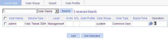
2. Click Add.
The local user configuration page appears. On this page, you can create a local user of any type except guest.
Figure 60 Local user configuration page
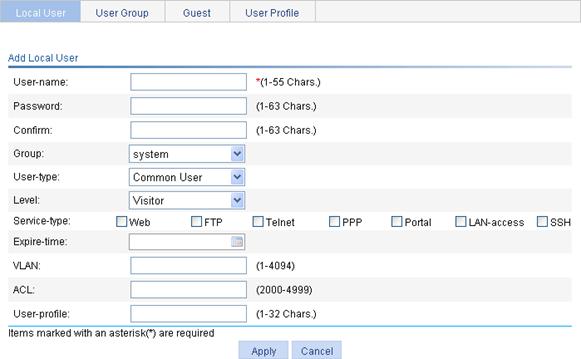
3. Configure a local user as described in Table 20.
4. Click Apply.
|
Item |
Description |
|
Username |
Specify a name for the local user. |
|
Password |
Specify a password for the local user and confirm the password. The two passwords must be identical.
It is a good practice to specify a password with no leading spaces. The spaces will be ignored, but they count at the user login page. |
|
Confirm |
|
|
Group |
Select a user group for the local user. For information about user group configuration, see "Configuring a user group." |
|
User Type |
Specify the user type for the local user: · Common User. · Security Log Admin—Users of this type can only manage security log files through the web interface. Only Users of this type can manage security log files. · Guest Admin—Users of this type can only manage guest accounts through the web interface, log in to the Authentication > User > Guest page to add, modify, or delete a guest user. |
|
Level |
Select an authorization level for the local user, which can be Visitor, Monitor, Configure, or Management, in ascending order of priority. A local user has the rights of the specified level and all levels lower than the specified level (if any). · Visitor—A user of this level can perform ping and trace route operations but cannot read any data from the device or configure the device. · Monitor—A user of this level can read data from the device but cannot configure the device. · Configure—A user of this level can read data from the device and configure the device but cannot upgrade the device software, add/delete/modify users, or backup/restore configuration files. · Management—A user of this level can perform all operations except for security log file reading and management.
This option is effective only for web, FTP, Telnet, and SSH users. |
|
Service Type |
Select the service types for the local user to use, including FTP, Telnet, PPP, Portal, LAN access (accessing through the Ethernet, such as 802.1X users), and SSH.
· If you do not specify any service type for a local user who uses local authentication, the user cannot pass authentication and cannot log in. · The service type of the guest administrator and security log administrator is web. · The service type of the guest administrator and security log administrator is Portal and LAN-Access. |
|
Expire-time |
Specify an expiration time for the local user. When authenticating a local user with the expiration time argument configured, the access device checks whether the expiration time has elapsed. If not, the device permits the user to log in. |
|
VLAN |
Specify the VLAN to be authorized to the local user after the user passes authentication.
This option is effective only for Portal and LAN-access users. |
|
ACL |
Specify the ACL to be used by the access device to restrict the access of the local user after the user passes authentication.
This option is effective only for PPP, Portal, and LAN-access users. |
|
User-profile |
Specify the user profile for the local user.
This option is effective only for PPP, Portal, and LAN-access users. |
Configuring a user group
1. Select Authentication > Users from the navigation tree.
2. Click the User Group tab to display the existing user groups.
Figure 61 User group list
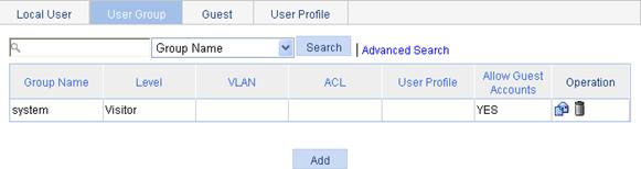
3. Click Add to enter the user group configuration page.
Figure 62 User group configuration page
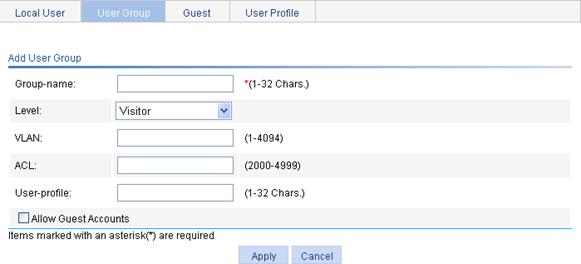
4. Add a user group as described in Table 21.
5. Click Apply.
|
Item |
Description |
|
Group-name |
Specify a name for the user group. |
|
Level |
Select an authorization level for the user group, which can be Visitor, Monitor, Configure, or Management, in ascending order of priority. |
|
VLAN |
Specify the VLAN to be authorized to a user in the user group after the user passes authentication. |
|
ACL |
Specify the ACL to be used by the access device to restrict the access of a user in the user group after the user passes authentication. |
|
User-profile |
Specify the user profile for the user group. |
|
Allow Guest Accounts |
Specify whether to allow a guest to join the user group.
User group system is an optional group of guest accounts by default, and cannot be modified. |
Configuring a guest
Two categories of administrators can configure guests: guest administrators and administrators of the management level.
|
|
NOTE: For information about user type and authorization level, see Table 20. |
Procedure for a management level administrator to configure a guest
1. Select Authentication > Users from the navigation tree.
2. Click the Guest tab to display the guest information.
Figure 63 Guest list
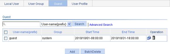
3. Click Add to enter the guest configuration page.
Figure 64 Guest configuration page
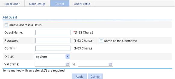
4. Configure a single guest or a batch of guests as described in Table 22.
5. Click Apply.
|
Item |
Description |
|
Create Users in a Batch |
Specify whether to create guests in a batch. |
|
Username |
Specify a name for the guest when users are not created in a batch. |
|
User-name(prefix) |
Specify the username prefix and number for guests to be created in a batch. For example, if you specify the username prefix as abc and number as 50, 50 guests will be created, with the usernames abc0 through abc49. |
|
Password |
Specify a password for the guest. If you select this option, you do not need to enter the password and confirm password, and the guest password is the same as the username. If you do not select this option, you must enter the password and confirm password, and they must be the same.
If the password starts with a space, the space will be omitted. |
|
Same as the Username |
|
|
Confirm |
|
|
Group |
Select a user group for the guest. For information about user group configuration, see "Configuring a user group." |
|
ValidTime |
Specify a valid time range for the guest, including the start time and end time. When authenticating a local user with the valid time argument configured, the access device checks whether the valid time has elapsed. If not, the device permits the user to log in. |
Procedure for a guest administrator to configure a guest
|
|
NOTE: A guest administrator can only manage guests through the web interface. |
1. Log in to the AC as a guest administrator and select Authentication > User from the navigation tree.
The guest management page appears.
Figure 65 Guest management page
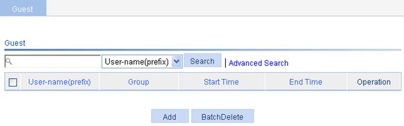
2. Click Add to enter the guest configuration page.
Figure 66 Guest configuration page
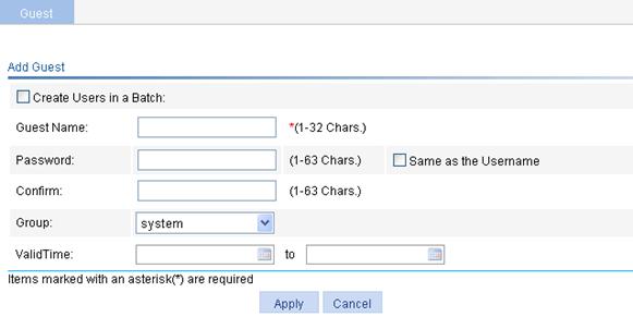
3. Configure the guest as described in Table 22.
4. Click Apply.
|
|
NOTE: The guest accounts are also displayed in
the local user list. You can click the icon |
Configuring a user profile
1. Select Authentication > Users from the navigation tree.
2. Click the User Profile tab to display the existing user profiles
Figure 67 User profile list
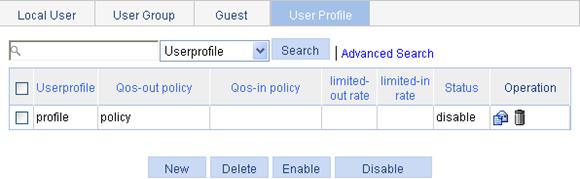
3. Click Add to enter the user profile name configuration page.
Figure 68 User profile name configuration item

4. Enter a profile name profile.
5. Click Apply.
The user profile configuration page appears.
Figure 69 User profile configuration page
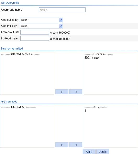
6. Configure the profile as described in Table 23.
7. Click Apply.
|
Item |
Description |
|
Userprofile name |
This field displays the user profile name. |
|
Qos-out policy |
Select a QoS policy in the outbound direction. |
|
Qos-in policy |
Select a QoS policy in the inbound direction. |
|
limited-out rate |
Specify the rate limit in the outbound direction. |
|
limited-in rate |
Specify the rate limit in the inbound direction. |
|
Services permitted |
Specify the wireless services permitted in the user profile: Select the services in the Services list box and click the < button to add them to the Selected services list box. The available wireless services are those configured on the page you enter by selecting Wireless Service > Access Service. For more information, see "Access service configuration." |
|
APs permitted |
Specify the APs permitted in the user profile: Select the APs in the APs list box and click the < button to add them to the Selected APs list box. The available APs are those you configured on the page you enter by selecting AP > AP Group. For more information, see "AP configuration." |
8. From the page displaying the existing user profiles, select the option before the user profile to be enabled.
9. Click Enable.
|
|
NOTE: · By default, a newly added user profile is disabled. · A user profile takes effect and the authentication server notifies users of authentication results only after the user profile is enabled. Therefore, if you do not enable the user profile, users using the user profile will not be able to get online. · Only enabled user profiles can be referenced by users. Disabling a user profile logs out all users using the user profile. · Enabled user profiles cannot be modified or removed. To modify or remove an enabled user profile, you must disable it first. |
PKI overview
The Public Key Infrastructure (PKI) is a general security infrastructure for providing information security through public key technologies, and it is the most widely applied encryption mechanism currently. H3C's PKI system provides certificate management for IP Security (IPsec), and Secure Sockets Layer (SSL).
PKI, also called asymmetric key infrastructure, uses a key pair to encrypt and decrypt data. The key pair consists of a private key and a public key. The private key must be kept secret but the public key needs to be distributed. Data encrypted by one of the two keys can only be decrypted by the other.
A key problem of PKI is how to manage the public keys. Currently, PKI employs the digital certificate mechanism to solve this problem. The digital certificate mechanism binds public keys to their owners, helping distribute public keys in large networks securely.
With digital certificates, the PKI system provides network communication and e-commerce with security services such as user authentication, data non-repudiation, data confidentiality, and data integrity.
The PKI technology can satisfy the security requirements of online transactions. As an infrastructure, PKI has a wide range of applications. Here are some application examples:
· Secure email—Emails require confidentiality, integrity, authentication, and non-repudiation. PKI can address these needs. The secure email protocol that is currently developing rapidly is Secure/Multipurpose Internet Mail Extensions (S/MIME), which is based on PKI and allows for transfer of encrypted mails with signature.
· Web security—For Web security, two peers can establish a Secure Sockets Layer (SSL) connection first for transparent and secure communications at the application layer. With PKI, SSL enables encrypted communications between a browser and a server. Both the communication parties can verify the identity of each other through digital certificates.
|
|
NOTE: For more information about PKI, see Security Configuration Guide. |
Configuring PKI
The system supports the following PKI certificate request modes:
· Manual—In manual mode, you must retrieve a CA certificate, generate a local RSA key pair, and submit a local certificate request for an entity.
· Auto—In auto mode, an entity automatically requests a certificate through the Simple Certification Enrollment Protocol (SCEP) when it has no local certificate or the present certificate is about to expire.
You can specify the PKI certificate request mode for a PKI domain. Different PKI certificate request modes require different configurations.
Recommended configuration procedure for manual request
|
Step |
Remarks |
|
Required. Create a PKI entity and configure the identity information. A certificate is the binding of a public key and an entity, where an entity is the collection of the identity information of a user. A CA identifies a certificate applicant by entity. The identity settings of an entity must be compliant to the CA certificate issue policy. Otherwise, the certificate request might be rejected. |
|
|
Required. Create a PKI domain, setting the certificate request mode to Manual. Before requesting a PKI certificate, an entity needs to be configured with some enrollment information, which is referred to as a PKI domain. A PKI domain is intended only for convenience of reference by other applications like IKE and SSL, and has only local significance. |
|
|
Required. Generate a local RSA key pair. By default, no local RSA key pair exists. Generating an RSA key pair is an important step in certificate request. The key pair includes a public key and a private key. The private key is kept by the user, and the public key is transferred to the CA along with some other information.
If a local certificate already exists, you must remove the certificate before generating a new key pair, so as to keep the consistency between the key pair and the local certificate. |
|
|
4. Retrieving the CA certificate |
Required. Certificate retrieval serves the following purposes: · Locally store the certificates associated with the local security domain for improved query efficiency and reduced query count, · Prepare for certificate verification.
If a local CA certificate already exists, you cannot perform the CA certificate retrieval operation. This will avoid possible mismatch between certificates and registration information resulting from relevant changes. To retrieve the CA certificate, you must remove the CA certificate and local certificate first. |
|
Required. When requesting a certificate, an entity introduces itself to the CA by providing its identity information and public key, which will be the major components of the certificate. A certificate request can be submitted to a CA in online mode or offline mode. · In online mode, if the request is granted, the local certificate will be retrieved to the local system automatically. · In offline mode, you must retrieve the local certificate by an out-of-band means.
If a local certificate already exists, you cannot perform the local certificate retrieval operation. This will avoid possible mismatch between the local certificate and registration information resulting from relevant changes. To retrieve a new local certificate, you must remove the CA certificate and local certificate first. |
|
|
Optional. If the certificate to be retrieved contains an RSA key pair, you must destroy the existing RSA key pair. Otherwise, the certificate cannot be retrieved. Destroying the existing RSA key pair also destroys the corresponding local certificate. |
|
|
Required if you request a certificate in offline mode. Retrieve an existing certificate and display its contents.
· If you request a certificate in offline mode, you must retrieve the CA certificate and local certificate by an out-of-band means. · Before retrieving a local certificate in online mode, be sure to complete LDAP server configuration. |
|
|
Optional. Retrieve a CRL and display its contents. |
Recommended configuration procedure for automatic request
|
Step |
Remarks |
|
Required. Create a PKI entity and configure the identity information. A certificate is the binding of a public key and an entity, where an entity is the collection of the identity information of a user. A CA identifies a certificate applicant by entity. The identity settings of an entity must be compliant to the CA certificate issue policy. Otherwise, the certificate request might be rejected. |
|
|
Required. Create a PKI domain, setting the certificate request mode to Auto. Before requesting a PKI certificate, an entity needs to be configured with some enrollment information, which is referred to as a PKI domain. A PKI domain is intended only for convenience of reference by other applications like IKE and SSL, and has only local significance. |
|
|
Optional. If the certificate to be retrieved contains an RSA key pair, you must destroy the existing RSA key pair. Otherwise, the certificate cannot be retrieved. Destroying the existing RSA key pair also destroys the corresponding local certificate. |
|
|
Optional. Retrieve an existing certificate and display its contents.
· Before retrieving a local certificate in online mode, be sure to complete LDAP server configuration. · If a CA certificate already exists, you cannot retrieve another CA certificate. This restriction avoids inconsistency between the certificate and registration information due to related configuration changes. To retrieve a new CA certificate, remove the existing CA certificate and local certificate first. |
|
|
Optional. Retrieve a CRL and display its contents. |
Creating a PKI entity
1. Select Authentication > Certificate Management from the navigation tree.
The PKI entity list page is displayed by default.
Figure 70 PKI entity list
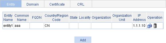
2. Click Add to enter the PKI entity configuration page.
Figure 71 PKI entity configuration page
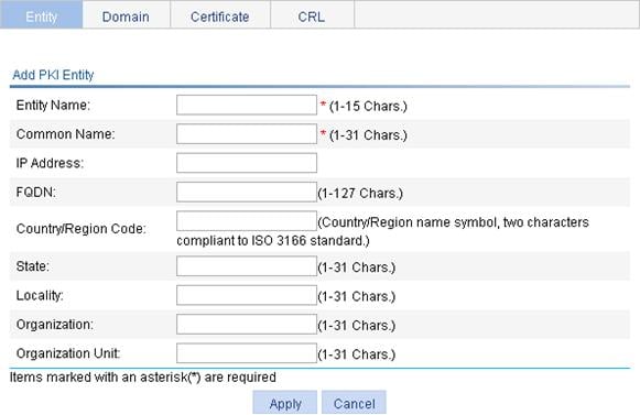
3. Configure the parameters as described in Table 24.
4. Click Apply.
|
Item |
Description |
|
Entity Name |
Enter the name for the PKI entity. |
|
Common Name |
Enter the common name for the entity. |
|
IP Address |
Enter the IP address of the entity. |
|
FQDN |
Enter the fully qualified domain name (FQDN) for the entity. An FQDN is a unique identifier of an entity on the network. It consists of a host name and a domain name and can be resolved to an IP address. For example, www.whatever.com is an FQDN, where www indicates the host name and whatever.com the domain name. |
|
Country/Region Code |
Enter the country or region code for the entity. |
|
State |
Enter the state or province for the entity. |
|
Locality |
Enter the locality for the entity. |
|
Organization |
Enter the organization name for the entity. |
|
Organization Unit |
Enter the unit name for the entity. |
Creating a PKI domain
1. Select Authentication > Certificate Management from the navigation tree.
2. Click the Domain tab.
Figure 72 PKI domain list
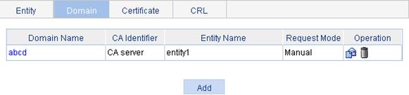
3. Click Add to enter the PKI domain configuration page.
Figure 73 PKI domain configuration page
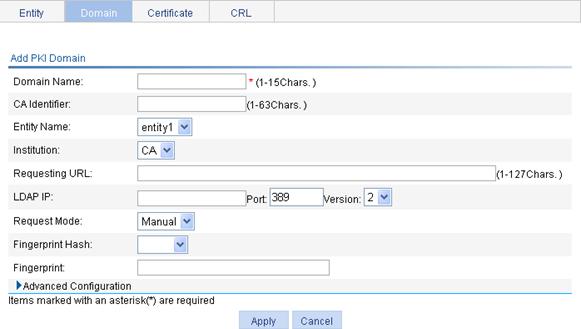
4. Configure the parameters as described in Table 25.
5. Click Apply.
|
Item |
Description |
|
Domain Name |
Enter the name for the PKI domain. |
|
CA Identifier |
Enter the identifier of the trusted CA. An entity requests a certificate from a trusted CA. The trusted CA takes the responsibility of certificate registration, distribution, and revocation, and query. In offline mode, this item is optional. In other modes, this item is required. |
|
Entity Name |
Select the local PKI entity. When submitting a certificate request to a CA, an entity needs to show its identity information. Available PKI entities are those that have been configured. |
|
Institution |
Select the authority for certificate request. · CA—Indicates that the entity requests a certificate from a CA. · RA—Indicates that the entity requests a certificate from an RA. RA is recommended. |
|
Requesting URL |
Enter the URL of the RA. The entity will submit the certificate request to the server at this URL through the SCEP protocol. The SCEP protocol is intended for communication between an entity and an authentication authority. In offline mode, this item is optional. In other modes, this item is required.
This item does not support domain name resolution. |
|
LDAP IP |
Enter the IP address, port number and version of the LDAP server. In a PKI system, the storage of certificates and CRLs is a crucial problem, which is usually addressed by deploying an LDAP server. |
|
Port |
|
|
Version |
|
|
Request Mode |
Select the online certificate request mode, which can be auto or manual. |
|
Password Encrypt |
Select this box to display the password in cipher text. This box is available only when the certificate request mode is set to Auto. |
|
Password |
Enter the password for certificate revocation. This item is available only when the certificate request mode is set to Auto. |
|
Fingerprint Hash |
Specify the fingerprint used for verifying the CA root certificate. After receiving the root certificate of the CA, an entity needs to verify the fingerprint of the root certificate, namely, the hash value of the root certificate content. This hash value is unique to every certificate. If the fingerprint of the root certificate does not match the one configured for the PKI domain, the entity will reject the root certificate. · If you specify MD5 as the hash algorithm, enter an MD5 fingerprint. The fingerprint must a string of 32 characters in hexadecimal notation. · If you specify SHA1 as the hash algorithm, enter an SHA1 fingerprint. The fingerprint must a string of 40 characters in hexadecimal notation. · If you do not specify the fingerprint hash, do not enter any fingerprint. The entity will not verify the CA root certificate, and you yourself must make sure that the CA server is trusted.
The fingerprint must be configured if you specify the certificate request mode as Auto. If you specify the certificate request mode as Manual, you can leave the fingerprint settings null. If you do not configure the fingerprint, the entity will not verify the CA root certificate and you yourself must make sure that the CA server is trusted. |
|
Fingerprint |
|
|
Polling Count |
Set the polling interval and attempt limit for querying the certificate request status. After an entity makes a certificate request, the CA might need a long period of time if it verifies the certificate request in manual mode. During this period, the applicant needs to query the status of the request periodically to get the certificate as soon as possible after the certificate is signed. |
|
Polling Interval |
|
|
Enable CRL Checking |
Click this box to specify that CRL checking is required during certificate verification. |
|
CRL Update Period |
Enter the CRL update period, that is, the interval at which the PKI entity downloads the latest CRLs. This item is available when the Enable CRL Checking box is selected. By default, the CRL update period depends on the next update field in the CRL file. |
|
CRL URL |
Enter the URL of the CRL distribution point. This item is available when the Enable CRL Checking box is selected. When the URL of the CRL distribution point is not set, you should acquire the CA certificate and a local certificate, and then acquire a CRL through SCEP.
This item does not support domain name resolution. |
Generating an RSA key pair
1. Select Authentication > Certificate Management from the navigation tree
2. Click the Certificate tab.
Figure 74 Certificate configuration page
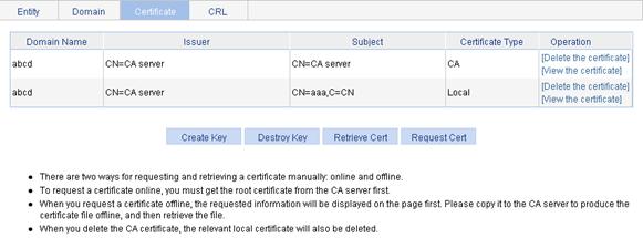
3. Click Create Key to enter RSA key pair parameter configuration page.
Figure 75 Key pair parameter configuration page
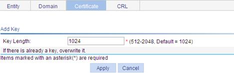
4. Set the key length.
5. Click Apply.
Destroying the RSA key pair
1. Select Authentication > Certificate Management from the navigation tree.
2. Click the Certificate tab.
3. Click Destroy Key to enter RSA key pair destruction page.
4. Click Apply to destroy the existing RSA key pair and the corresponding local certificate.
Figure 76 Key pair destruction page
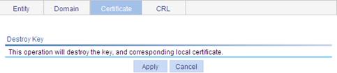
Retrieving and displaying a certificate
You can download an existing CA certificate or local certificate from the CA server and save it locally. To do so, you can use offline mode or online mode. In offline mode, you can retrieve a certificate by an out-of-band means like FTP, disk, email and then import it into the local PKI system.
To retrieve a certificate:
1. Select Authentication > Certificate Management from the navigation tree.
2. Click the Certificate tab.
3. Click Retrieve Cert to enter PKI certificate retrieval page.
Figure 77 PKI certificate retrieval page
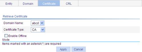
4. Configure the parameters as described in Table 26.
5. Click Apply.
|
Item |
Description |
|
Domain Name |
Select the PKI domain for the certificate. |
|
Certificate Type |
Select the type of the certificate to be retrieved, which can be CA or local. |
|
Enable Offline Mode |
Click this box to retrieve a certificate in offline mode (that is, by an out-of-band means like FTP, disk, or email) and then import the certificate into the local PKI system. |
|
Get File From Device |
Specify the path and name of the certificate file if you retrieve the certificate in offline mode. · If the certificate file is saved on the device, select Get File From Device and then specify the path of the file on the device. · If the certificate file is saved on a local PC, select Get File From PC and. then specify the path to the file and select the partition of the device for saving the file. |
|
Get File From PC |
|
|
Password |
Enter the password for protecting the private key if you retrieve the certificate in offline mode. The password was specified when the certificate was exported. |
6. After retrieving a certificate, click View Cert corresponding to the certificate from the PKI certificates list to display the contents of the certificate.
Figure 78 Certificate information
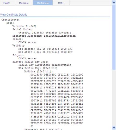
Requesting a local certificate
1. Select Authentication > Certificate Management from the navigation tree.
2. Click the Certificate tab.
3. Click Request Cert to enter the local certificate request page.
Figure 79 Local certificate request page
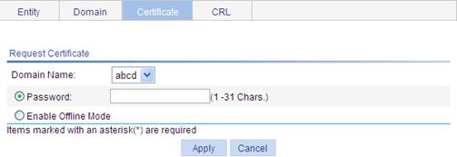
4. Configure the parameters as described in Table 27.
|
Item |
Description |
|
Domain Name |
Select the PKI domain for the certificate. |
|
Password |
Enter the password for certificate revocation. |
|
Enable Offline Mode |
Click this box to request a certificate in offline mode, that is, by an out-of-band means like FTP, disk, or email. |
5. Click Apply.
If you request the certificate in online mode, the system displays "Certificate request has been submitted." Click OK. If you request the certificate in offline mode, the system displays the offline certificate request information. You can submit the information to the CA by an out-of-band means.
Figure 80 Offline certificate request information page
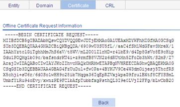
Retrieving and displaying a CRL
1. Select Authentication > Certificate Management from the navigation tree.
2. Click the CRL tab.
Figure 81 CRL page
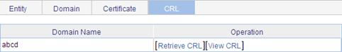
3. Click Retrieve CRL to retrieve the CRL of a domain.
4. Click View CRL for the domain to display the contents of the CRL.
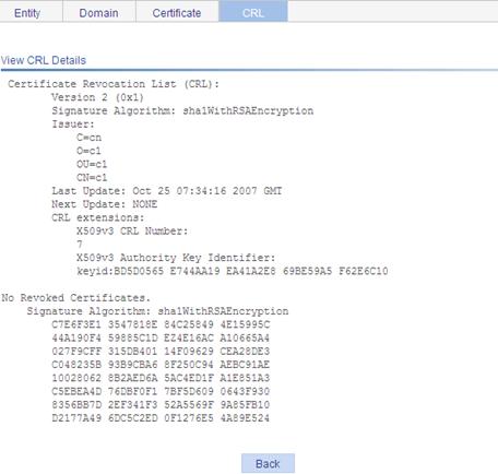
Certificate management configuration example
Network requirements
As shown in Figure 83, configure the AC as the PKI entity, so that:
· The AC submits a local certificate request to the CA server, which runs the RSA Keon software.
· The AC acquires CRLs for certificate verification.
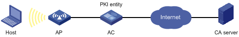
Configuring the CA server
1. Create a CA server named myca.
In this example, you must first configure the basic attributes of Nickname and Subject DN on the CA server: the nickname is the name of the trusted CA, and the subject DN is the DN attributes of the CA, including the common name (CN), organization unit (OU), organization (O), and country (C). Leave the default values of the other attributes.
2. Configure extended attributes.
After you configure the basic attributes, perform configuration on the Jurisdiction Configuration page of the CA server. This includes selecting the proper extension profiles, enabling the SCEP autovetting function, and adding the IP address list for SCEP autovetting.
3. Configure the CRL publishing behavior
After you complete the previous configuration, perform CRL related configurations.
In this example, select the local CRL publishing mode of HTTP and set the HTTP URL to http://4.4.4.133:447/myca.crl.
After this configuration, make sure that the system clock of the AC is synchronous to that of the CA, so that the AC can request certificates and retrieve CRLs properly.
Configuring the AC
1. Create a PKI entity.
a. Select Authentication > Certificate Management from the navigation tree.
The PKI entity list page is displayed by default.
b. Click Add.
c. Enter aaa as the PKI entity name.
d. Enter ac as the common name.
e. Click Apply.
Figure 84 Configuring a PKI entity
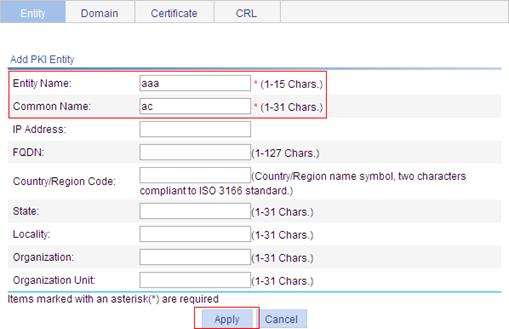
2. Create a PKI domain.
a. Click the Domain tab.
b. Click Add.
c. Enter torsa as the PKI domain name.
d. Enter myca as the CA identifier.
e. Select aaa as the local entity.
f. Select CA as the authority for certificate request.
g. Enter http://4.4.4.133:446/c95e970f632d27be5e8cbf80e971d9c4a9a93337 as the URL for certificate request. The URL must be in the format of http://host:port/Issuing Jurisdiction ID, where Issuing Jurisdiction ID is the hexadecimal string generated on the CA.
h. Select Manual as the certificate request mode.
i. Click the expansion button before Advanced Configuration to display the advanced configuration items.
j. Click the Enable CRL Checking box.
k. Enter http://4.4.4.133:447/myca.crl as the CRL URL.
l. Click Apply.
The system displays "Fingerprint of the root certificate not specified. No root certificate validation will occur. Continue?"
m. Click OK.
Figure 85 Configuring a PKI domain
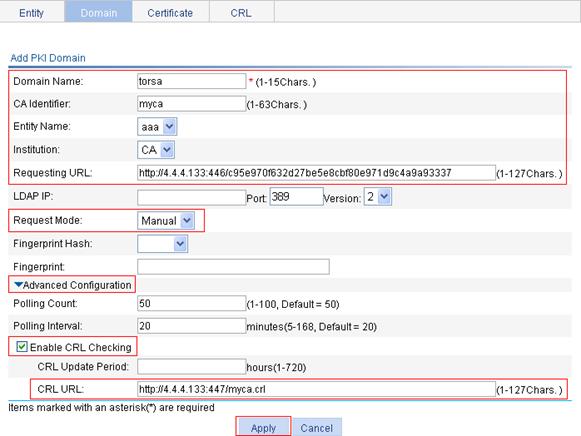
3. Generate an RSA key pair.
a. Click the Certificate tab.
b. Click Create Key to enter the page.
c. Enter 1024 for the key length.
d. Click Apply to generate an RSA key pair.
Figure 86 Generating an RSA key pair
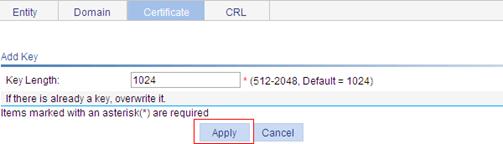
4. Retrieve the CA certificate.
a. Click the Certificate tab.
b. Click Retrieve Cert.
c. Select torsa as the PKI domain.
d. Select CA as the certificate type.
e. Click Apply.
Figure 87 Retrieving the CA certificate
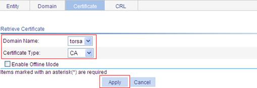
5. Request a local certificate.
a. Click the Certificate tab.
b. Click Request Cert.
c. Select torsa for the PKI domain.
d. Select Password and then enter challenge-word as the password.
e. Click Apply.
The system displays "Certificate request has been submitted".
f. Click OK.
Figure 88 Requesting a local certificate
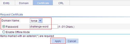
6. Retrieve the CRL.
a. Click the CRL tab.
b. Click Retrieve CRL of the PKI domain of torsa.
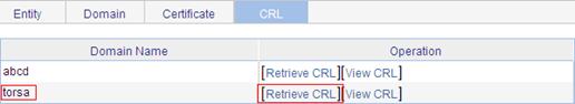
Verifying the configuration
After the configuration, you can select Certificate Management > Certificate from the navigation tree to view detailed information about the retrieved CA certificate and local certificate, or select Certificate Management > CRL from the navigation tree to view detailed information about the retrieved CRL.
Configuration guidelines
When you configure PKI, note the following guidelines:
· Make sure the clocks of entities and the CA are synchronous. Otherwise, the validity period of certificates will be abnormal.
· The Windows 2000 CA server has some restrictions on the data length of a certificate request. If the PKI entity identity information in a certificate request goes beyond a certain limit, the server will not respond to the certificate request.
· The SCEP plug-in is required when you use the Windows Server as the CA. In this case, you need to specify RA as the authority for certificate request when you configure the PKI domain.
· The SCEP plug-in is not required when you use the RSA Keon software as the CA. In this case, you need to specify CA as the authority for certificate request when you configure the PKI domain.
