- Table of Contents
-
- H3C WX Series Access Controllers Web-Based Configuration Guide(R3308 R2308)-6W107
- 00-Preface
- 01-About the WX Series Access Controllers Web Configuration Guide
- 02-Quick Start
- 03-Web Overview
- 04-Summary
- 05-Device
- 06-Network
- 07-AP Configuration
- 08-Wireless Service
- 09-WLAN Roaming Configuration
- 10-Radio Configuration
- 11-Authentication
- 12-Security
- 13-QoS configuration
- 14-Advanced Settings
- 15-Stateful Failover Configuration
- Related Documents
-
| Title | Size | Download |
|---|---|---|
| 14-Advanced Settings | 927.81 KB |
Configuring WLAN advanced settings
Setting a country/region code·
Configuring continuous transmitting mode
Configuring a channel busy test
Advanced settings configuration examples
1+1 fast backup configuration example
1+N backup configuration example
AP-based session-mode load balancing configuration example
AP-based traffic-mode load balancing configuration example
Group-based session-mode load balancing configuration example
Group-based traffic-mode load balancing configuration example
Wireless location configuration example
Wireless sniffer configuration example
Band navigation configuration example
Advanced settings overview
Country/Region code
Radio frequencies for countries and regions vary based on country regulations. A country/region code determines characteristics such as frequency range, channel, and transmit power level. Configure the valid country/region code for a WLAN device to meet the specific country regulations.
1+1 AC backup
|
|
NOTE: Support for the 1+1 backup feature may vary depending on your device model. For more information, see "Feature matrixes." |
Dual-link backup
1. Dual links
Dual links allow for AC backup. An AP establishes links with two different ACs. The active AC provides services for APs in the network and the standby AC provides backup service for the active AC. If the active AC fails, the standby AC takes over to provide services for the APs.
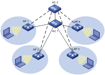
AC 1 is operating in active mode and providing services to AP 1, AP 2, AP 3, and AP 4. AC 2 is operating in standby mode. APs are connected to AC 2 through backup links. When AC 1 is down, AC 2 converts to operate in active mode even when AC 1 is up again, in which case, AC 1 is in standby mode. However, this is not so if an AC is configured as the primary AC. For more information about primary AC, see "Primary AC recovery."
2. Using fast link fault detection, you can configure 1+1 fast backup (see "1+1 fast backup") to provide uninterrupted services.
Primary AC provides a mechanism to make sure the primary AC is chosen in precedence by APs as an active AC. When the primary AC goes down, the APs switch to connect to the standby AC. As soon as the active AC recovers, the APs automatically connect to the primary AC again.
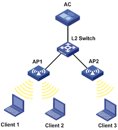
Figure 2 Primary AC recovery
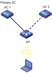
AC 1 is the primary AC with the connection priority of 7, and it establishes a connection with the AP. AC 2 acts as the secondary AC. If AC 1 goes down, AC 2 takes over to provide services to AP until AC 1 recovers. Once the primary AC is reachable again, the AP automatically establishes a connection with the primary AC. For more information about priority configuration, see "Configuring AP connection priority."
1+1 fast backup
Fast link fault detection allows two ACs in 1+1 backup to detect the failure of each other in time. To achieve this, a heartbeat detection mechanism is used. When the active AC goes down, the standby AC can quickly detect the faults and become the new active AC.
|
|
NOTE: Support for the 1+1 fast backup feature may vary depending on your device model. For more information, see "Feature matrixes." |
1+N AC backup
1+N AC backup allows an AC to operate as a backup for multiple ACs. The active ACs independently provide services for APs that connect to them, and the only one standby AC provides backup service for the active ACs. If an active AC goes down, the APs connecting to it can detect the failure quickly and make connections to the standby AC. As soon as the active AC recovers, the APs automatically connect to the original active AC again. This makes sure the standby AC operates as a dedicated backup for the active ACs. 1+N AC backup delivers high reliability and saves network construction cost greatly.
Continuous transmitting mode
The continuous transmitting mode is used for test only. Do not use the function unless necessary.
Channel busy test
The channel busy test is a tool to test how busy a channel is. It tests channels supported by the country/region code one by one, and provides a busy rate for each channel. This avoids the situation that some channels are heavily loaded and some are idle.
During a channel busy test, APs do not provide any WLAN services. All the connected clients are disconnected and WLAN packets are discarded.
WLAN load balancing
WLAN load balancing dynamically adjusts loads among APs to ensure adequate bandwidth for clients. It is mainly used in high-density WLAN networks.
Requirement of WLAN load-balancing implementation
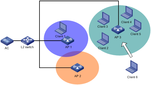
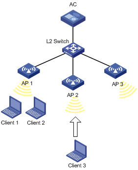
As shown in Figure 3, Client 6 wants to associate with AP 3. AP 3 has reached its maximum load, so it rejects the association request. Then, Client 6 tries to associate with AP 1 or AP 2, but it cannot receive signals from these two APs, so it has to resend an association request to AP 3.
Therefore, to implement load-balancing, the APs must be managed by the same AC, and the clients can find the APs.
Figure 3 Requirement of WLAN load-balancing implementation
Load-balancing modes
The AC supports two load balancing modes, session mode and traffic mode.
· Session mode load-balancing
Session-mode load balancing is based on the number of clients associated with the AP/radio.
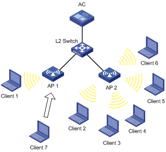
As shown in Figure 4, Client 1 is associated with AP 1, and Client 2 through Client 6 are associated with AP 2. The AC has session-mode load balancing configured: the maximum number of sessions is 5 and the maximum session gap is 4. Then, Client 7 sends an association request to AP 2. The maximum session threshold and session gap have been reached on AP 2, so it rejects the request. At last, Client 7 associates with AP 1.
Figure 4 Network diagram for session-mode load balancing
· Traffic mode load-balancing
Traffic snapshot is considered for traffic mode load balancing.
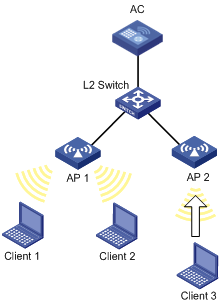
As shown in Figure 5, Client 1 and Client 2 that run 802.11g are associated with AP 1. The AC has traffic-mode load balancing configured: the maximum traffic threshold is 10% and the maximum traffic gap is 20%. Then, Client 3 wants to access the WLAN through AP 1. The maximum traffic threshold and traffic gap (between AP 1 and AP 2) have been reached on AP 1, so it rejects the request. At last, Client 3 associates with AP 2.
Figure 5 Network diagram for traffic-mode load balancing
Load-balancing methods
The AC supports AP-based load balancing and group-based load balancing.
AP-based load balancing can be either implemented among APs or among the radios of an AP.
¡ AP-based load balancing—APs can carry out either session-mode or traffic-mode load balancing as configured. An AP starts load balancing when the maximum threshold and gap are reached, and does not accept any association requests unless the load decreases below the maximum threshold or the gap is less than the maximum gap. However, if a client has been denied more than the specified maximum times, the AP considers that the client is unable to associate to any other AP and accepts the association request from the client.
¡ Radio-based load balancing—The radios of an AP that is balanced can carry out either session-mode or traffic-mode load balancing as configured. A radio starts load balancing when the maximum threshold and gap are reached and will reject any association requests unless the load decreases below the maximum threshold or the gap is less than the maximum gap. However, if a client has been denied more than the specified maximum times, the AP considers that the client is unable to associate to any other AP and accepts the association request from the client.
To balance loads among the radios of different APs, you can add them to the same load balancing group.
The radios in a load balancing group can carry out either session-mode or traffic-mode load balancing as configured. The radios that are not added to any load balancing group do not carry out load balancing. A radio in a load balancing group starts load balancing when the maximum threshold and gap are reached on it, and the radio does not accept any association requests unless the load decreases below the maximum threshold or the gap is less than the maximum gap. However, if a client has been denied more than the specified maximum times, the AP considers that the client is unable to associate to any other AP and accepts the association request from the client.
AP version setting
A fit AP is a zero-configuration device. It can automatically discover an AC after power-on. To make sure a fit AP can associate with an AC, their software versions must be consistent by default, which complicates maintenance. This task allows you to designate the software version of an AP on the AC, so that they can associate with each other even if their software versions are inconsistent.
Switching to fat AP
You can switch the working mode of an AP between the fit mode and the fat mode.
Wireless location
Wireless location is a technology to locate, track and monitor specified devices by using WiFi-based Radio Frequency Identification (RFID) and sensors. With this function enabled, APs send Tag or MU messages to an AeroScout Engine (referred to as AE hereinafter), which performs location calculation and then sends the data to the graphics software. You can get the location information of the assets by maps, forms, or reports. Meanwhile, the graphics software provides the search, alert and query functions to facilitate your operations.
Wireless location can be applied to medical monitoring, asset management, and logistics, helping users effectively manage and monitor assets.
Architecture of the wireless location system
A wireless location system is composed of three parts: devices or sources to be located, location information receivers and location systems.
· Devices or sources to be located, which can be Tags (small, portable RFIDs, which are usually placed or glued to the assets to be located) of Aero Scout or Mobile Units (MU). The MUs are wireless terminals or devices running 802.11. The tags and MUs can send wireless messages periodically.
· Location information receivers, for example, 802.11 APs, and AeroScout Exciters that are standard compliant Tags to send wireless messages but do not collect location information.
· Location systems, including location server, AE calculation software, and different types of graphics software.
Wireless locating process
A wireless location system can locate wireless clients, APs, rogue APs, rogue clients, Tags and other devices supporting WLAN protocols. Except Tags, all wireless devices will be identified as MUs by the wireless location system.
1. Send Tag and MU messages
A Tag message is a message sent by an RFID. A Tag message contains the channel number so that an AP can filter Tag messages whose channel numbers are not consistent with the AP's operating channel. To make sure more Tags can be detected by the AP, a Tag sends messages on different channels. A Tag periodically sends messages on one or multiple pre-configured channels, and then sends location messages on channels 1, 6, and 11 in turn periodically.
MU messages are sent by standard wireless devices. An MU message does not contain the channel number, so an AP cannot filter MU messages whose channel numbers are not consistent with the AP's operating channel or illegal packets, which is done by the location server according to a certain algorithm and rules.
2. Collect Tag and MU messages
The working mode of an AP determines how it collects Tag and MU messages:
¡ When the AP operates in monitor mode or hybrid mode, it can locate wireless clients or other wireless devices that are not associated with it.
¡ When the AP operates in normal mode, it can only locate wireless clients associated with it. The wireless location system considers wireless clients associated with the AP as wireless clients, and considers wireless clients or other wireless devices not associated with the AP as unknown devices.
|
|
NOTE: · For more information about monitor mode and hybrid mode, see "WLAN security configuration." · An AP operates in normal mode when it functions as a WLAN access point. For more information, see "Configuring access services." |
After the processes, the AP begins to collect Tag and MU messages.
· Upon receiving Tag messages (suppose that the Tags mode has been configured on the AC, and the location server has notified the AP to report Tag messages), the AP checks the Tag messages, encapsulates those passing the check and reports them to the location server. The AP encapsulates Tag messages by copying all the information (message header and payload inclusive) except the multicast address, and adding the BSSID, channel, timestamp, data rate, RSSI, SNR and radio mode of the radio on which the relevant Tag messages were received.
· Upon receiving MU messages (suppose that the MUs mode has been configured on the AC, and the location server has notified the AP to report MU messages), the AP checks the messages, encapsulates those that pass the check and reports the messages to the location server. The AP encapsulates an MU message by copying its source address, Frame Control field and Sequence Control field, and adding the BSSID, channel, timestamp, data rate, RSSI, SNR and radio mode of the radio on which the relevant Tag messages were received.
3. Calculate the locations of Tags or MUs
After receiving Tag and MU messages from APs, the location server uses an algorithm to calculate the locations of the Tag and MU devices according to the RSSI, SNR, radio mode and data rate carried in the messages, and displays the locations on the imported map. Typically, a location server can calculate the locations as long as more than 3 APs operating in monitor or hybrid report Tag or MU messages.
Wireless sniffer
In a wireless network, it is difficult to locate signal interference or packet collision by debugging information or terminal display information of WLAN devices. To facilitate the troubleshooting, configure an AP as a packet sniffer to listen to, capture, and record wireless packets. The sniffed packets are recorded in the .dmp file for troubleshooting.
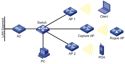
As shown in Figure 6, enable wireless sniffer on the Capture AP. The Capture AP is able to listen to the wireless packets in the network, including the packets from other APs, rouge APs, and clients. Administrators can download the .dmp file to the PC and make further analysis.
Band navigation
The 2.4 GHz band is often congested. Band navigation enables APs to accept dual-band (2.4 GHz and 5 GHz) clients on their 5 GHz radio, increasing overall network performance.
When band navigation is enabled, the AP directs clients to its 2.4 GHz or 5 GHz radio by following these principles:
· For a 2.4 GHz client, the AP associates to the client after rejecting it several times.
· For a dual-band client, the AP directs the client to its 5 GHz radio.
· For a 5 GHz- client, the AP associates to the client on its 5 GHz radio.
The AP checks the RSSI of a dual-band client before directing the client to the 5 GHz radio. If the RSSI is lower than the value, the AP does not direct the client to the 5 GHz band.
If the number of clients on the 5 GHz radio reaches the upper limit, and the gap between the number of clients on the 5 GHz radio and that on the 2.4 GHz radio reaches the upper limit, the AP denies the client’s association to the 5 GHz radio, and allows new clients to associate to the 2.4 GHz radio. If a client has been denied more than the maximum times on the 5 GHz radio, the AP considers that the client is unable to associate to any other AP, and allows the 5 GHz radio to accept the client.
Configuring WLAN advanced settings
Setting a country/region code
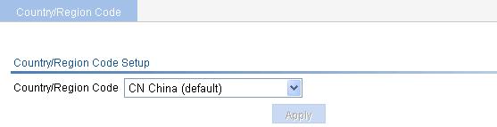
1. Select Advanced > Country/Region Code from the navigation tree to enter the page for setting a country/region code.
Figure 7 Setting a country/region code
2. Configure a country/region code as described in Table 1.
3. Click Apply.
|
Item |
Description |
|
Country/Region Code |
Select a country/region code. Configure the valid country/region code for a WLAN device to meet the country regulations. If the list is grayed out, the setting is preconfigured to meet the requirements of the target market and is locked. It cannot be changed. |
If you do not specify a country/region code for an AP, the AP uses the global country/region code configured on this page. For how to specify the country/region code for an AP, see "Quick start." If an AP is configured with a country/region code, the AP uses its own country code.
Some ACs and fit APs have fixed country/region codes, whichever is used is determined as follows: An AC's fixed country/region code cannot be changed, and all managed fit APs whose country/region codes are not fixed must use the AC's fixed country/region code. A fit AP's fixed country/region code cannot be changed and the fit AP can only use the country/region code. If an AC and a managed fit AP use different fixed country/region codes, the fit AP uses its own fixed country/region code.
Configuring 1+1 AC backup
Configuring AP connection priority
1. Select AP > AP Setup from the navigation tree.
2.
Click the icon ![]() corresponding to the target AP to enter the configuration page.
corresponding to the target AP to enter the configuration page.
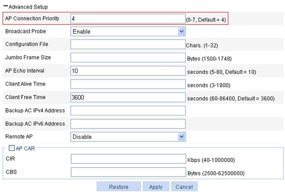
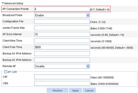
3. Expand the Advanced Setup area.
Figure 8 Configuring connection priority
4. Configure an AP connection priority as described in Table 2.
5. Click Apply.
|
Item |
Description |
|
AP Connection Priority |
Set the priority for the AP connection to the AC. |
Configure 1+1 AC backup
1. Select Advanced > AC Backup from the navigation tree.
Figure 9 Configuring AC backup
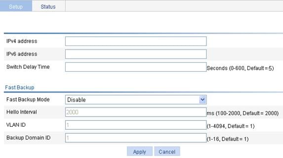
2. Configure an IP address and switch delay time for the backup AC as described in Table 3.
3. Click Apply.
|
Item |
Description |
|
|
IPv4 |
Select IPv4, and enter the IPv4 address of the backup AC. |
If the backup AC is configured on the page you enter by selecting AP > AP Setup, the configuration is used in precedence. For more information, see "AP configuration." The access mode configuration on the two ACs should be the same. Specify the IP address of one AC on the other AC in an AC backup. |
|
IPv6 |
Select IPv6, and enter the IPv6 address of the backup AC. |
|
|
Switch Delay Time |
Delay time for the AP to switch from the primary AC to the backup AC. |
|
Configuring 1+1 fast backup
1. Select Advanced > AC Backup from the navigation tree.
Figure 10 Configuring fast backup
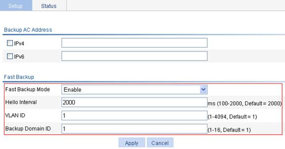
2. Configure fast backup as described in Table 4.
3. Click Apply.
|
Item |
Description |
|
Fast Backup Mode |
· disable—Disable fast backup. · enable—Enable fast backup. By default, fast backup is disabled. |
|
Hello Interval |
Heartbeat interval for an AC connection. If no heartbeat is received during the continuous three intervals, the device considers the peer is down. The value range varies with devices. For more information, see "Feature matrixes." |
|
VLAN ID |
ID of the VLAN to which the port where the backup is performed belongs. |
|
Backup Domain ID |
ID of the domain to which the AC belongs. |
Displaying status information of 1+1 fast backup
1. Select Advanced > AC Backup from the navigation tree.
2. Click the Status tab to enter the page as shown in Figure 11.
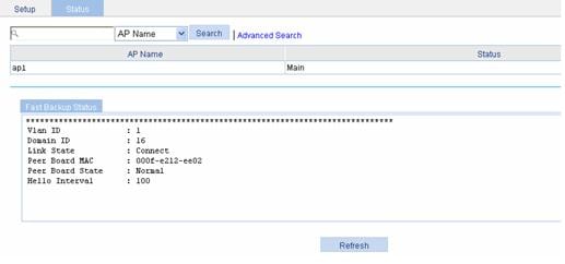
Table 5 Field description
|
Field |
Description |
|
AP Name |
Select to display the AP connecting to the AC. |
|
Status |
Current status of the current AC. |
|
Vlan ID |
ID of the VLAN to which the port belongs. |
|
Domain ID |
Domain to which the AC belongs. |
|
Link State |
Link status of the AC connection: · Close—No connection is established. · Init—The connection is being set up. · Connect—The connection has been established. |
|
Peer Board MAC |
MAC address of the peer AC. |
|
Peer Board State |
Status of the peer AC. · Normal—The peer AC is normal. · Abnormal—The peer AC is malfunctioning. · Unknown—No connection is present. |
|
Hello Interval |
Heartbeat interval for an AC connection. |
Configuring 1+N AC backup
Configuring AP connection priority
1. Select AP > AP Setup from the navigation tree.
2.
Click the icon ![]() corresponding to the target AP to enter the configuration page.
corresponding to the target AP to enter the configuration page.
3. Expand Advanced Setup.
Figure 12 Configuring connection priority
4. Configure a connection priority as described in Table 6.
5. Click Apply.
|
Item |
Description |
|
AP Connection Priority |
Set the priority for the AP connection to the AC. |
Configuring 1+N AC backup
1. Select AP > AP Setup from the navigation tree.
2.
Click the ![]() icon corresponding to the target AP to enter the configuration
page.
icon corresponding to the target AP to enter the configuration
page.
3. Expand Advanced Setup.
Figure 13 Configuring 1+N AC backup
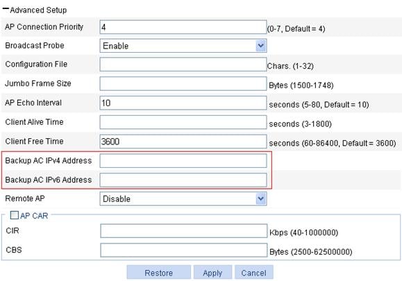
4. Configure 1+N back as described in Table 7.
5. Click Apply.
|
Item |
Description |
|
|
Backup AC IPv4 Address |
Set the IPv4 address of the backup AC. |
If the global backup AC is also configured on the page you enter by selecting Advanced > AC Backup, this configuration is used in precedence. |
|
Backup AC IPv6 Address |
Set the IPv6 address of the backup AC. |
|
Configuring continuous transmitting mode
1. Select Advanced > Continuous Transmit from the navigation tree to enter the continuous transmitting mode configuration page.
Figure 14 Configuring continuous transmitting mode
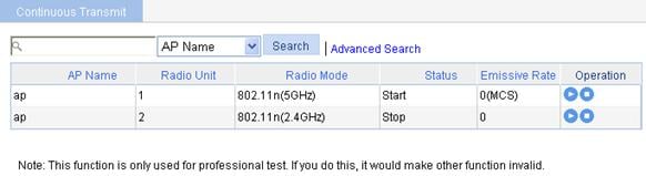
2.
Click the ![]() icon corresponding
to the target radio to enter the page for configuring transmission
rate. The transmission rate varies with radio mode.
icon corresponding
to the target radio to enter the page for configuring transmission
rate. The transmission rate varies with radio mode.
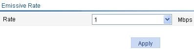
¡ When the radio mode is 802.11a/b/g, the page as shown in Figure 15 appears. Select a transmission rate from the list.
Figure 15 Selecting a transmission rate (802.11b/g)
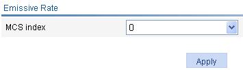
¡ When the radio mode is 802.11n, the page as shown in Figure 16 appears. Select an MCS index value to specify the 802.11n transmission rate. For more information about MCS, see "Radio configuration."
Figure 16 Selecting an MCS index (802.11n)
3. Click Apply.
To stop the continuous transmitting mode, click
the ![]() icon of the
target radio. After the continuous transmit is stopped, the transmission rate
value on the page as shown in Figure
15 displays as 0.
icon of the
target radio. After the continuous transmit is stopped, the transmission rate
value on the page as shown in Figure
15 displays as 0.
|
|
NOTE: When the continuous transmit is enabled, do not make any operations other than transmission rate configuration. |
Configuring a channel busy test
1. Select Advanced > Channel Busy Test from the navigation tree to enter the channel busy test configuration page.
Figure 17 Configuring channel busy test
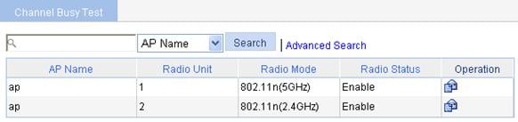
2.
Click the ![]() icon corresponding to a target AP to enter channel busy testing page.
icon corresponding to a target AP to enter channel busy testing page.
Figure 18 Test busy rate of channels
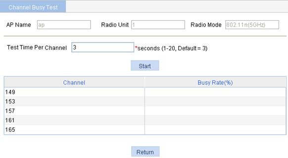
3. Configure channel busy test as described in Table 8.
4. Click Start to start the testing.
|
Item |
Description |
|
AP Name |
Display the AP name. |
|
Radio Unit |
Display the radio unit of the AP. |
|
Radio Mode |
Display the radio mode of the AP. |
|
Test time per channel |
Set a time period in seconds within which a channel is tested. It defaults to 3 seconds. |
|
|
NOTE: · During a channel busy test, the AP does not provide any WLAN services. All the connected clients are disconnected. · Before the channel busy test completes, do not start another test for the same channel. |
Configuring load balancing
Band navigation and load balancing can be used simultaneously.
Configuration prerequisites
Before you configure load balancing, make sure:
· The target APs are associated with the same AC.
· The clients can find the APs.
· The fast association function is disabled. By default, the fast association function is disabled. For more information about fast association, see "Configuring access services."
Recommended configuration procedure
|
Task |
Remarks |
|
Required. |
|
|
2. Configuring AP-based load balancing |
Required. Use either approach. · AP-based load balancing—After you complete Configuring a load balancing mode, the AC adopts AP-based load balancing by default. · Group-based load balancing—H3C recommends that you complete Configuring a load balancing mode first. A load balancing group takes effect only when a load balancing mode is configured. |
|
Optional. This configuration takes effect for both AP-based load balancing and radio group based load balancing. |
Configuring a load balancing mode
|
|
NOTE: If the AC has a load balancing mode configured but has no load balancing group created, it uses AP-based load balancing by default. |
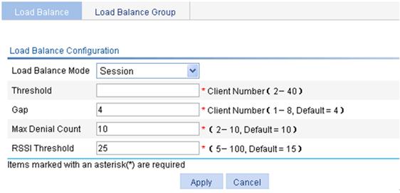
1. Configure session-mode load balancing
a. Select Advanced > Load Balance from the navigation tree to enter the page for setting load balancing.
b. Select Session from the Loadbalance Mode list.
c. Click Apply.
Figure 19 Setting session-mode load balancing
|
Item |
Description |
|
Loadbalance Mode |
Select Session. The function is disabled by default. |
|
Threshold |
Load balancing is carried out for a radio when the session threshold and session gap threshold are reached. |
|
Gap |
Load balancing is carried out for a radio when the session threshold and session gap threshold are reached. |
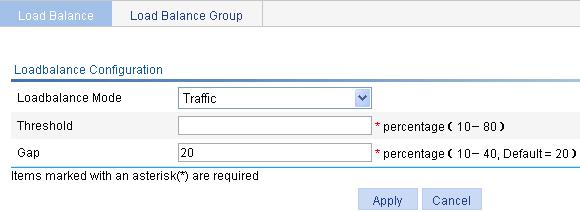
2. Configure traffic-mode load balancing
a. Select Advanced > Load Balance from the navigation tree to enter the page for setting load balancing.
b. Select Traffic from the Loadbalance Mode list.
c. Click Apply.
Figure 20 Setting traffic-mode load balancing
|
Item |
Description |
|
Loadbalance Mode |
Select Traffic. The function is disabled by default. |
|
Traffic |
Load balancing is carried out for a radio when the traffic threshold and traffic gap threshold are reached. |
|
Gap |
Load balancing is carried out for a radio when the traffic threshold and traffic gap threshold (the traffic gap between the two APs) are reached. |
|
|
NOTE: If you select the traffic-mode load balancing, the maximum throughput of 802.11g/802.11a is 30 Mbps. |
Configuring group-based load balancing
|
|
NOTE: H3C recommends you to complete Configuring a load balancing mode on the Load Balance tab page. A load balancing group takes effect only when a load balancing mode is configured. |
1. Select Advanced > Load Balance from the navigation tree.
2. Click the Load Balance Group tab to enter the page for configuring a load balancing group.
3. Click Add.
Figure 21 Configuring a load balancing group
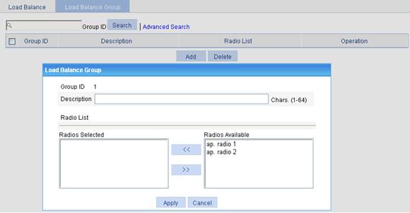
4. Configure a load balancing group as described in Table 11.
5. Click Apply.
|
Item |
Remarks |
|
Group ID |
Display the ID of the load balancing group |
|
Description |
Configure a description for the load balancing group. By default, the load balancing group has no description. |
|
Radio List |
· In the Radios Available area, select the target radios, and then click << to add them into the Radios Selected area. · In the Radios Selected area, select the radios to be removed, and then click >> to remove them from the load balancing group. |
Configuring parameters that affect load balancing
1. Select Advanced > Load Balance from the navigation tree. See Figure 19.
2. Configure parameters that affect load balancing as described in Table 12.
3. Click Apply.
|
Item |
Remarks |
|
Max Denial Count |
Maximum denial count of client association requests. If a client has been denied more than the specified maximum times, the AP considers that the client is unable to associate to any other AP and accepts the association request from the client. |
|
RSSI Threshold |
Load balancing RSSI threshold. A client may be detected by multiple APs. An AP considers a client whose RSSI is lower than the load balancing RSSI threshold as not detected. If only one AP can detect the client, the AP increases the access probability for the client even if it is over-loaded. |
Configuring AP
Upgrading AP version
1. Select Advanced > AP from the navigation tree.
2. On the AP Module tab, select the desired AP.
3. Click Version Update to enter the page for AP version upgrade.
Figure 22 AP version update
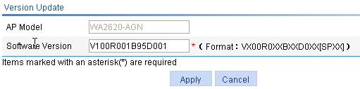
4. Configure AP upgrade as described in Table 13.
5. Click Apply.
|
Item |
Description |
|
AP Model |
Display the selected AP model. |
|
Software Version |
Enter the software version of the AC in a correct format. |
Switching to fat AP
1. Select Advanced > AP Setup from the navigation tree.
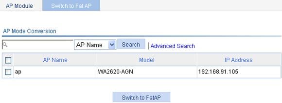
2. Click the Switch to Fat AP tab.
3. Select the desired AP.
4. Click Switch to Fat AP to perform AP working mode switchover.
Figure 23 Switching to fat AP
|
|
NOTE: Before you switch the work mode, you must download the fat AP software to the AP. |
Configuring wireless location
1. Select Advanced > Wireless Location from the navigation tree to enter the page for displaying and configuring wireless location on an AC.
Figure 24 Configuring wireless location

2. Configure wireless location as described in Table 14.
3. Click Apply.
|
Item |
Description |
|
Location Function |
· Enable—Enables the wireless location function globally. The device begins to listen to packets when wireless location is enabled. · Disable—Disables wireless location globally. To ensure the location function, complete the configuration on the location server and AC: · On the location server—Configure whether to locate Tags or MUs, Tag message multicast address, and dilution factor on the location server. These settings will be notified to the APs through the configuration message. For more information about location server and configuration parameters, see the location server manuals. · On the AC—Configure the AP mode settings, and enable the wireless location function. When configurations are correctly made, APs wait for the configuration message sent by the location server, and after receiving that message, start to receive and report Tag and MU messages. |
|
Vendor Port |
Set listening port number for vendors. The port number must be the same as that defined in AE. |
|
Tag Mode |
Select this option to enable the Tag report function on the radio (you also need to enable Tags mode on the AE). |
|
MU Mode |
Select this option to enable the MU report function on the radio (you also need to enable the MUs mode on the AE). |
An AP reports IP address change and device reboot events to the location server so that the location server is able to respond in time. The AP reports a reboot message according to the IP address and port information of the location server recorded in its flash.
· The AP updates the data in the flash after receiving a configuration message. To protect the flash, the AP does not update the flash immediately after receiving a configuration message, but waits for 10 minutes. If receiving another configuration message within 10 minutes, the AP only updates the configuration information in the cache, and when the 10-minute timer is reached, saves the cache information in the flash.
· If the AP reboots within 10 minutes after receiving the first configuration message, and no configuration is saved in the flash, it does not send a reboot message to the location server.
Configuring wireless sniffer
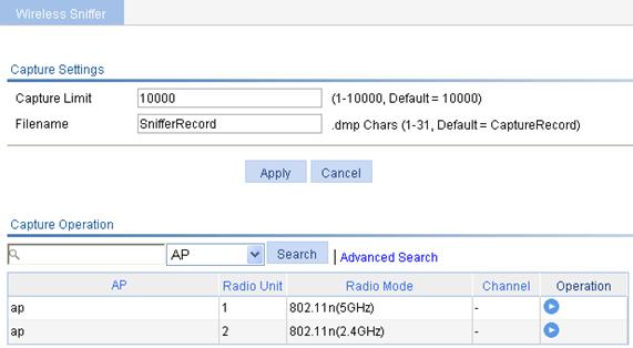
1. Select Advanced > Wireless Sniffer from the navigation tree to enter the wireless sniffer configuration page.
Figure 25 Configuring wireless sniffer
2.
To enable the wireless sniffer function for a
specified radio, click the ![]() icon of the radio.
icon of the radio.
Before you enable wireless sniffer, make sure the AP operates in normal mode and in run state. Wireless sniffer can be enabled for only one radio configured with a fixed channel.
When you configure wireless sniffer, follow these guidelines:
· Auto APs do not support wireless sniffer.
· Wireless sniffer can be enabled for one radio at one time.
· When the Capture AP is capturing packets, if the radio for which the wireless sniffer is disabled, the Capture AP is deleted, the Capture AP is disconnected from the AC, or the number of captured packets reaches the upper limit, the sniffer operation is stopped and the packets are saved to the specified .dmp file. The default storage medium varies with device models.
· You can click Stop to stop the wireless sniffer, and choose whether to save the packets to a CAP file. If not, no CAP file is generated.
· The working mode of the AP cannot be changed when it is capturing packets.
|
|
NOTE: Do not enable or run wireless services for the radio with wireless sniffer enabled. Disable all wireless services before enabling wireless sniffer. |
3. Configure wireless sniffer as described in Table 15.
4. Click Apply.
|
Item |
Description |
|
Capture Limit |
The maximum number of packets that can be captured. Once the limit is exceeded, the device stops capturing packets.
You cannot change the value when the device is capturing packets. |
|
Filename |
Name of the CAP file to which the packets are saved. By default, the name is SnifferRecord.
You cannot change the fine name when the device is capturing packets. |
Configuring band navigation
When band navigation is enabled, the client association efficiency is affected, so this feature is not recommended in a scenario where most clients use 2.4 GHz.
Band navigation is not recommended in a delay-sensitive network.
Band navigation and load balancing can be used simultaneously.
Configuration prerequisites
To enable band navigation to operate properly, make sure of the following:
· The fast association function is disabled. By default, the fast association function is disabled. For more information about fast association, see "Configuring access services."
· Band navigation is enabled for the AP. By default, band navigation is enabled for the AP.
· The SSID is bound to the 2.4 GHz and 5 GHz radios of the AP.
Configuring band navigation
1. Select Advance > Band Navigation from the navigation tree.
Figure 26 Configuring band navigation
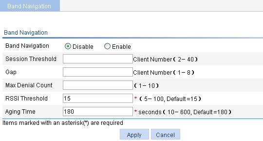
2. Configure band navigation as described in Table 16.
3. Click Apply.
|
Item |
Description |
|
Band Navigation |
· Enable—Enable band navigation. · Disable—Disable band navigation. By default, band navigation is disabled globally. |
|
Session Threshold |
· Session Threshold—Session threshold for clients on the 5 GHz band. · Gap—Session gap, which is the number of clients on the 5 GHz band minus the number of clients on the 2.4 GHz band. If the number of clients on the 5 GHz radio has reached the upper limit, and the gap between the number of clients on the 5 GHz radio and that on the 2.4 GHz radio has reached the upper limit, the AP denies the client’s association to the 5 GHz radio, and allows new clients to associate to the 2.4 GHz radio. When band navigation is enabled, the value is 0 by default. To restore the default value 0, delete the configured number. |
|
Gap |
|
|
Max Denial Count |
Maximum denial count of client association requests. If a client has been denied more than the maximum times on the 5 GHz radio, the AP considers that the client is unable to associate to any other AP, and allows the 5 GHz radio to accept the client. When band navigation is enabled, the value is 0 by default. To restore the default value 0, delete the configured number. |
|
RSSI Threshold |
Band navigation RSSI threshold. The AP checks the RSSI of a dual-band client before directing the client to the 5 GHz radio. If the RSSI is lower than the value, the AP does not direct the client to the 5 GHz band. |
|
Aging Time |
Client information aging time. The AP records the client information when a client tries to associate to it. If the AP receives the probe request or association request sent by the client before the aging time expires, the AP refreshes the client information and restarts the aging timer. If not, the AP removes the client information, and does not count the client during band navigation. |
Advanced settings configuration examples
1+1 fast backup configuration example
Network requirements
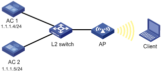
As shown in Figure 27, AC 1 and AC 2 backing up each other, with AC 1 acting as the active AC. When the active AC fails, the standby AC takes over to provide services, ensuring no service interruption.
· Assign a higher priority to the AP connection to AC 1, 6 in this example, to make sure AP will first establish a connection with AC 1. In this way, AC 1 acts as the active AC.
· When AC 1 is down, AC 2 becomes the new active AC.
· When the AC 1 recovers, no switchover to AC 1 occurs, in which case AC 2 remains the active and AC 1 acts as the standby AC. This is because the AP connection priority on AC 1 is not the highest.
Configuring AC 1
1. Configure AP to establish a connection between AC 1 and AP. For more information about configurations, see "Configuring access services."
2. Select AP > AP Setup from the navigation tree.
3.
Click the icon ![]() corresponding to the target AP to enter the configuration page.
corresponding to the target AP to enter the configuration page.
4. Expand Advanced Setup.
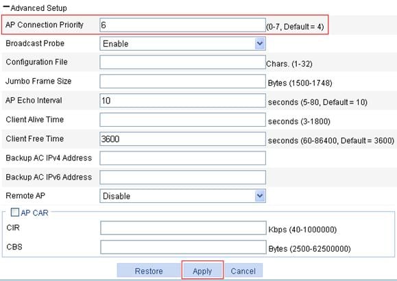
5. Set the connection priority to 6.
6. Click Apply.
Figure 28 Configuring the AP connection priority
7. Select Advance > AC Backup from the navigation tree.
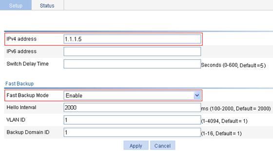
8. On the page that appears, set the IP address of the backup AC to 1.1.1.5 and select enable to enable the fast backup mode.
9. Click Apply.
Figure 29 Configuring the IP address of the backup AC
Configuring AC 2
1. Configure AP to establish a connection between AC 2 and AP.
For more information about configurations, see "Configuring access services."
2. Leave the default value of the AP connection priority unchanged. (Details not shown.)
3. Select Advanced > AC Backup from the navigation tree.
4. On the page that appears, set the address of the backup AC to 1.1.1.4 and select enable to enable the fast backup mode.
5. Click Apply.
Figure 30 Configuring the address of the backup AC

Verifying the configuration
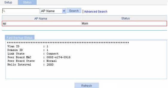
1. When AC 1 operates properly, view the AP status on AC 1 and AC 2 respectively. The AP connection priority on AC 1 is set to 6, the higher one, so AC 1 become the active AC. The AP establishes a connection to AC 1 in precedence.
a. On AC 1, select Advanced > AC Backup from the navigation tree.
b. Click the Status tab to enter the page as shown in Figure 31.
The status information shows that AC 1 is the active AC.
Figure 31 Displaying the AP status on AC 1
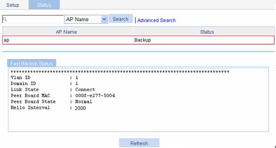
c. On AC 2, select Advanced > AC Backup from the navigation tree.
d. Click the Status tab.
The information shows that AC 1 is acting as the standby AC.
Figure 32 Displaying the AP status on AC 2
2. When AC 1 operates properly, display the client status on AC 1 and AC 2. Client establish connections with the AP through AC 1 and AC 2 has backed up the client status.
a. On AC 1, select Summary > Client from the navigation tree.
b. Click the Detail Information tab.
c. Click the name of the specified client to view the detailed information of the client.
The information shows that Client is running and is connecting to AC 1 through an active link.
Figure 33 Displaying the client information on AC 1
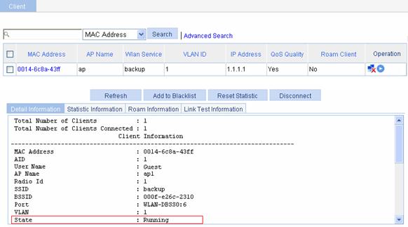
d. On AC 2, select Summary > Client from the navigation tree.
e. Click the Detail Information tab.
f. Click the name of the specified client to view the detailed information of the client.
The information shows that Client is running and is connecting to AC 2 through a standby link.
Figure 34 Displaying the client information on AC 2
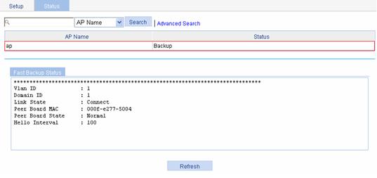
3. When AC 1 goes down, the standby AC, AC 2 detects the failure immediately through the heartbeat detection mechanism. Then AC 2 takes over to become the new active AC, providing services to AP.
¡ On AC 2 (the new active AC), display the AP status. (Details not shown.)
The information shows that AC 2 has become the active AC.
¡ On AC 2, display the client information. (Details not shown.)
The value for the State field becomes Running, which indicates that Client is connecting to AC 2 through an active link.
4. When AC 1 recovers, AC 2 still acts as the active AC and AC 1 becomes the standby AC. AC 1 establishes a backup link with the AP and backs up the client status.
Configuration guidelines
· The wireless services configured on the two ACs should be consistent.
· Specify the IP address of the backup AC on each AC.
· AC backup has no relation with the access authentication method; however, the authentication method of the two ACs must be the same.
1+N backup configuration example
Network requirements
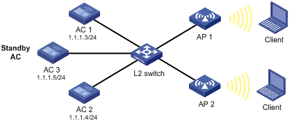
As shown in Figure 35, AC 1 and AC 2 are active ACs and AC 3 acts as the standby AC. When an active AC fails, AC 3, the standby AC, takes over to provide services. As soon as the active AC recovers, the AP connects to the original active AC again.
· AP connects to AC 1, AC 2, and AC 3 through a Layer 2 switch. The IP addresses of AC 1, AC 2 and AC 3 are 1.1.1.3, 1.1.1.4, and 1.1.1.5 respectively.
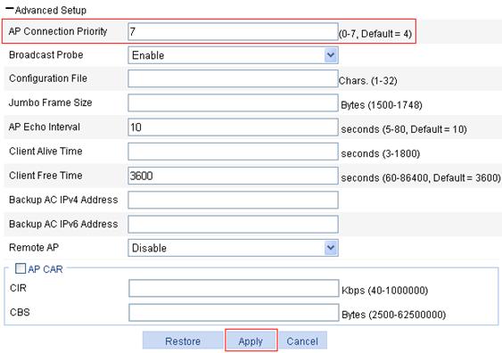
· Assign the highest AP connection priority of 7 on AC 1 and AC 2, to make sure AP 1 establishes a connection with AC 1, and AP 2 establishes a connection with AC 2.
· If any of the two active AC is down, AC 3 becomes the new active AC.
· When the faulty AC recovers, AP that connects to AC 3 automatically connects to the original active AC. This is because the AP connection priority on the active AC is the highest. In this way, AC 3 can always act as a dedicated standby AC to provide backup services for AC 1 and AC 2.
Configuring AC 1
1. Configure AC 1 so that a connection is set up between AC 1 and AP 1.
For more information about configurations, see "Configuring access services."
2. Select AP > AP Setup from the navigation tree.
3.
Click the icon ![]() corresponding to the target AP to enter the configuration page.
corresponding to the target AP to enter the configuration page.
4. Expand Advanced Setup.
5. Set the connection priority to 7.
6. Click Apply.
Figure 36 Configuring the AP connection priority for AP 1
Configuring AC 2
1. Configure AC 2 so that a connection is set up between AC 2 and AP 2.
For more information about configurations, see "Configuring access services."
2. Set the AP connection priority to 7.
The configuration steps are the same as those on AC 1 (Details not shown.).
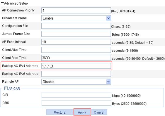
3. Configure AC 3 (the backup AC)
a. Configure the related information of AP 1 and AP 2.
For more information about configurations, see "Configuring access services."
b. Select AP > AP Setup from the navigation tree.
c.
Click the ![]() icon corresponding to the target AP to enter the configuration
page.
icon corresponding to the target AP to enter the configuration
page.
d. Expand Advanced Setup.
e. Enter 1.1.1.3 in the Backup AC IPv4 Address field.
f. Click Apply.
Figure 37 Backing up the IP address of AC 1
g. Select AP > AP Setup from the navigation tree.
h. Click the icon ![]() corresponding to the target AP to enter the configuration page.
corresponding to the target AP to enter the configuration page.
i. Expand Advanced Setup.
j. Enter 1.1.1.4 in the Backup AC IPv4 Address field.
k. Click Apply.
Figure 38 Backing up the IP address of AC 2

Verifying the configuration
1. When AC 1 goes down, AC 3 becomes the new active AC.
2. When AC 1 recovers, the AP connecting to AC 3 connects to AC 1 again. This is because the highest AP connection priority of 7 on AC 1 ensures an automatic switchover.
AP-based session-mode load balancing configuration example
Network requirements
· As shown in Figure 39, all APs operate in 802.11g mode. Client 1 is associated with AP 1. Client 2 through Client 6 are associated with AP 2.
· Configure session-mode load balancing on the AC. The threshold, that is, the maximum number of sessions, is 5, and the session gap is 4.
Configuration procedure
1. Before you configure load balancing, configure AP 1 and AP 2 on the AC to establish a connection between the AC and each AP.
For the related configuration, see "Configuring access services."
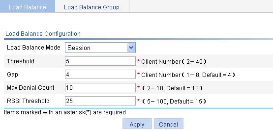
2. Configure session-mode load balancing:
a. Select Advanced > Load Balance from the navigation tree.
b. On the Load Balance tab, select the Session mode, enter the threshold 5, and use the default value for the gap.
c. Use the default values for Max Denial Count and RSSI Threshold.
d. Click Apply.
Figure 40 Setting session-mode load balancing
Verifying the configuration
Client 1 is associated with AP 1, and Client 2 through Client 6 are associated with AP 2. Because the number of clients associated with AP 1 reaches 5, and the session gap between AP 2 and AP 1 reaches 4, Client 7 is associated with AP 1.
Configuration guidelines
An AP starts session-mode load balancing only when both the maximum sessions and maximum session gap are reached.
AP-based traffic-mode load balancing configuration example
Network requirements
· As shown in Figure 41, all APs operate in 802.11g mode. Client 1 and Client 2 are associated with AP 1, and no client is associated with AP 2.
· Configure traffic-mode load balancing on the AC. The traffic threshold is 3 Mbps that corresponds to the threshold value of 10 in percentage, and the traffic gap is 12 Mbps that corresponds to the traffic gap value 40 in percentage.
Configuration procedure
1. Before you configure load balancing, configure AP 1 and AP 2 on the AC to establish a connection between the AC and each AP.
For the related configuration, see "Configuring access services."
2. Configure traffic-mode load balancing:
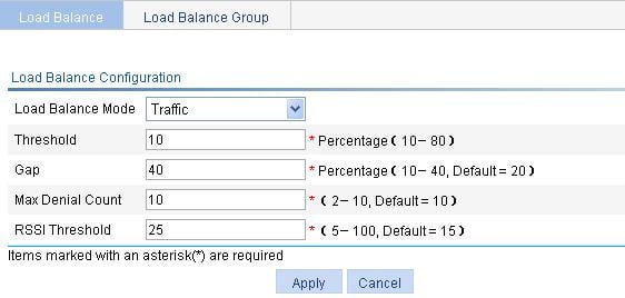
a. Select Advanced > Load Balance from the navigation tree.
b. On the Load Balance tab, select the Traffic mode, enter the threshold 10, and the traffic gap 40.
c. Use the default values for Max Denial Count and RSSI Threshold.
d. Click Apply.
Figure 42 Setting traffic-mode load balancing
Verifying the configuration
Client 1 and Client 2 are associated with AP 1. Add Client 3 to the network. When the maximum traffic threshold and traffic gap are reached on AP 1, Client 3 is associated with AP 2.
Configuration guidelines
An AP starts traffic-mode load balancing only when both the maximum traffic threshold and maximum traffic gap are reached.
Group-based session-mode load balancing configuration example
Network requirements
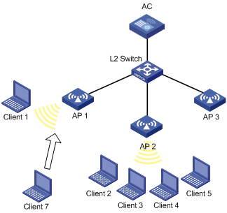
· As shown in Figure 43, all APs operate in 802.11g mode. Client 1 is associated with AP 1. Client 2 through Client 6 are associated with AP 2, and no client is associated with AP 3.
· Configure session-mode load balancing on the AC. The maximum number of sessions is 5 and the maximum session gap is 4.
· Session-mode load balancing is required on only radio 2 of AP 1 and radio 2 of AP 2. Therefore, add them into a load balancing group.
Configuration procedure
1. Before you configure load balancing, configure AP 1 and AP 2 on the AC to establish a connection between the AC and each AP.
For the related configuration, see "Configuring access services."
2. Configure load balancing:
a. Select Advanced > Load Balance from the navigation tree.
b. On the Load Balance tab, select Session from the Loadbalance Mode list, enter the threshold 5, and use the default value for the gap.
c. Use the default values for Max Denial Count and RSSI Threshold.
d. Click Apply..
Figure 44 Configuring session-mode load balancing
3. Configure a load balancing group:
a. Select Advanced > Load Balance from the navigation tree.
b. Click the Load Balance Group tab to enter the load balancing group configuration page.
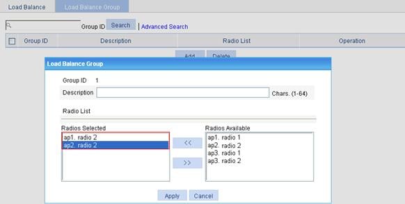
c. Click Add.
d. On the page that appears, select ap1. radio 2 and ap2. radio 2 in the Radios Available area, and click << to add them into the Radios Selected area and click Apply.
Figure 45 Configuring a load balancing group
Verifying the configuration
· Radio 2 of AP 1 and radio 2 of AP 2 are in the same load balancing group, and the radio of AP 3 does not belong to any load balancing group. Because load balancing takes effect on only radios in a load balancing group, AP 3 does not take part in load balancing.
· Assume Client 7 wants to associate with AP 2. The number of clients associated with radio 2 of AP 2 reaches 5 and the session gap between radio 2 of AP 2 and AP 1 reaches 4, so Client 7 is associated with AP 1.
Group-based traffic-mode load balancing configuration example
Network requirements
· As shown in Figure 46, all APs operate in 802.11g mode. Client 1 and Client 2 are associated with AP 1, and no client is associated with AP 2 and AP 3.
· Configure traffic-mode load balancing on the AC. The maximum traffic threshold is 10% and the maximum traffic gap is 20%.
· Traffic-mode load balancing is required on only radio 2 of AP 1 and radio 2 of AP 2. Therefore, add them to a load balancing group.
Configuration procedure
1. Before you configure load balancing, configure AP 1 and AP 2 on the AC to establish a connection between the AC and each AP.
For the related configuration, see "Configuring access services."
2. Configure load balancing:
a. Select Advanced > Load Balance from the navigation tree.
b. On the Load Balance tab, select Traffic from the Loadbalance Mode list, enter the threshold 10 and the gap 40.
c. Use the default values for Max Denial Count and RSSI Threshold.
d. Click Apply.
Figure 47 Configuring traffic load balancing
3. Configure a load balancing group:
a. Select Advanced > Load Balance from the navigation tree.
b. Click the Load Balance Group tab to enter the load balancing group configuration page.
c. Click Add.
d. On the page that appears, select ap1. radio 2 and ap2. radio 2 in the Radios Available area, click << to add them into the Radios Selected area, and click Apply.
Figure 48 Configuring a load balancing group

Verifying the configuration
· Radio 2 of AP 1 and radio 2 of AP 2 are in the same load balancing group, and the radio of AP 3 does not belong to any load balancing group. Because load balancing takes effect on only radios in a load balancing group, AP 3 does not take part in load balancing.
· Assume Client 3 wants to associate with AP 1. Because the maximum traffic threshold and traffic gap have been reached on radio 2 of AP 1, Client 3 is associated with AP 2.
Wireless location configuration example
Network requirements
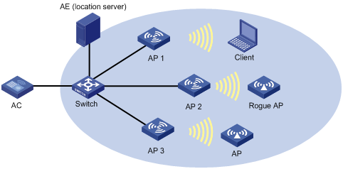
As shown in Figure 49, AP 1, AP 2, and AP 3 operate in monitor mode, and send the collected tag and MU messages to an AE (the location server), which performs location calculation and then sends the data to the graphics software. You can get the location information of the rogue AP, APs, and clients by maps, forms or reports.
Configuring the AE
1. Configure the IP addresses of AP 1, AP 2, and AP 3 on the AE, or select broadcast for the AE to discover APs.
2. Perform configuration related to wireless location on the AE.
Configuring AP 1 to operate in monitor mode
AP 1, AP 2, and AP 3 are configured similarly, and the following only describes how to configure AP 1 for illustration.
1. Select AP > AP Setup from the navigation tree.
2. Click Add.
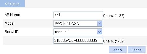
3. On the page that appears, enter the AP name ap1, select the model WA2620-AGN, select manual from the Serial ID list, enter the AP serial ID in the field, and click Apply.
4. Select Security > Rogue Detection from the navigation tree.
5.
On the AP Monitor tab, click the icon ![]() corresponding to the target AP to enter the page for configuring
the work mode.
corresponding to the target AP to enter the page for configuring
the work mode.
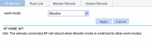
6. Select the work mode Monitor.
7. Click Apply.
Figure 51 Setting the work mode
Enabling 802.11n
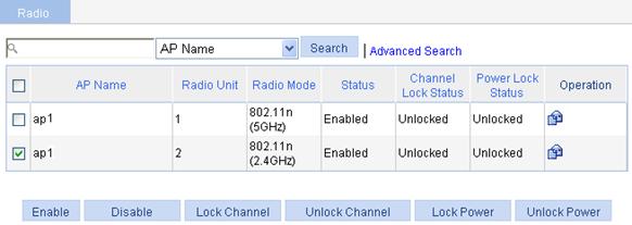
1. Select Radio > Radio from the navigation tree to enter the page for configuring radio.
2. Select the target AP.
3. Click Enable.
Figure 52 Enabling 802.11n (2.4 GHz)
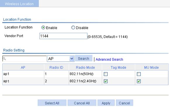
Enabling wireless location.
1. Select Advanced > Wireless Location from the navigation tree.
2. On the page that appears, select Enable, select the tag mode and MU mode for 802.11n (2.4 GHz).
3. Click Apply.
Figure 53 Enabling wireless location
Verifying the configuration
You can display the location information of the rogue AP, APs, and clients by maps, forms or reports.
Configuration guidelines
· Before you enable the wireless location function, make sure at least three APs operate in monitor or hybrid mode so that the APs can detect Tags and clients not associated with them, and the AE can implement location calculation.
· An AP monitors clients on different channels periodically, so if the Tag message sending interval is configured as 1 second, the AP scans and reports Tag messages every half a minute. If higher location efficiency is required, you can set the Tag sending interval to the smallest value, 124 milliseconds.
Wireless sniffer configuration example
Network requirements
As shown in Figure 54, configure a Capture AP, and enable wireless sniffer on this AP to capture wireless packets. The captured packets are then saved in a .dmp file for troubleshooting.
Configuring Capture_AP
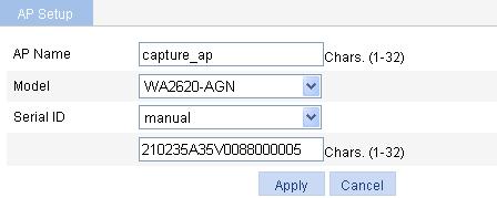
1. Select AP > AP Setup from the navigation tree.
2. Click Add.
3. On the page that appears, enter the AP name capture_ap, select the model WA2620-AGN., select manual from the Serial ID list, enter the AP serial ID in the field, and click Apply.
Figure 55 Creating a Capture AP
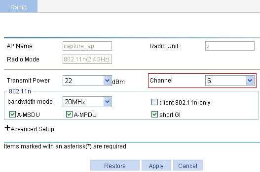
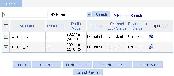
4. Select Radio > Radio from the navigation tree.
5.
Click the ![]() icon of the Capture_AP to enter the radio configuration page.
icon of the Capture_AP to enter the radio configuration page.
6. Select 6 from the Channel list.
7. Click Apply.
8. Select Radio > Radio from the navigation tree.
9. Select the target AP.
10. Click Enable.
Figure 57 Enabling 802.11n (2.4 GHz)
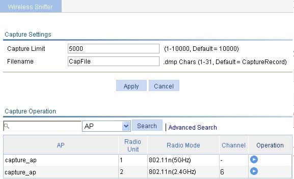
Configuring and enabling wireless sniffer
1. Select Advanced > Wireless Sniffer from the navigation tree.
2. On the page that appears, enter the capture limit 5000, enter the file name CapFile, and click Apply.
3.
Click the ![]() icon corresponding to the target radio to
enable wireless sniffer for the radio.
icon corresponding to the target radio to
enable wireless sniffer for the radio.
Figure 58 Configuring and enabling wireless sniffer
Verifying the configuration
· Capture AP captures wireless packets and saves the packets to a CAP file in the default storage medium. Administrators can download the file to the PC and get the packet information by using tools like Ethereal.
· When the total number of captured packets reaches the upper limit, Capture AP stops capturing packets.
Band navigation configuration example
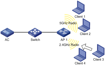
Network requirements
As shown in Figure 59, Client 1 through Client 4 try to associate to AP 1, and the two radios of AP 1 operate at 5 GHz and 2.4 GHz. Client 1, Client 2, and Client 3 are dual-band clients, and Client 4 is a single-band (2.4 GHz) client. Configure band navigation to direct clients to different radios of the AP.
Configuring the AC
To enable band navigation to operate properly, make sure of the following:
· The fast association function is disabled. By default, the fast association function is disabled.
· Band navigation is enabled for the AP. By default, band navigation is enabled for the AP.
1. Create an AP:
a. Select AP > AP Setup from the navigation tree.
b. Click New.
c. On the page that appears, enter the AP name ap 1, select the model WA2620E-AGN, select manual from the Serial ID list, and enter the AP serial ID in the field.
d. Click Apply.
2. Configure wireless service:
a. Select Wireless Service > Access Service from the navigation tree.
b. Click Add.
c. On the page that appears, set the service name to band-navigation, select the wireless service type Clear, and click Apply.
3. Enable wireless service:
a. Select Wireless Service > Access Service from the navigation tree.
b. Set the band-navigation box.
c. Click Enable.
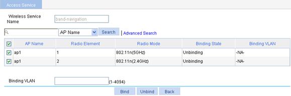
4. Bind an AP radio to the wireless service:
a. Select Wireless Service > Access Service from the navigation tree.
b. Click the ![]() icon for the wireless service band-navigation
to enter the page for binding an AP radio.
icon for the wireless service band-navigation
to enter the page for binding an AP radio.
c. Select the boxes before ap1 with radio types 802.11n(2.4GHz) and 802.11n(5GHz).
d. Click Bind.
5. Enable 802.11n(2.4GHz) and 802.11n(5GHz) radios:
a. Select Radio > Radio Setup from the navigation tree.
b. Select the boxes before ap1 with the radio mode 802.11n(2.4GHz) and 802.11n(5GHz).
c. Click Enable.
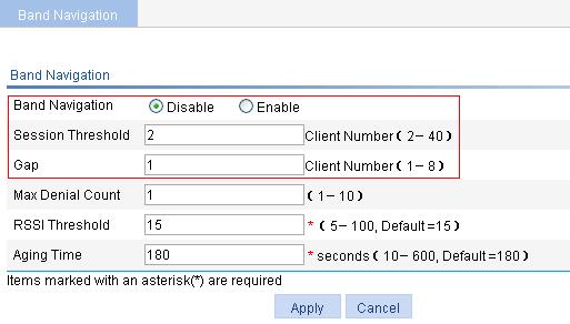
6. Configure band navigation:
a. Select Advance > Band Navigation from the navigation tree.
b. On the page that appears, click Enable, and type the Session Threshold 2 and Gap 1. Use the default values for other options.
c. Click Apply.
Figure 61 Configuring band navigation
Verifying the configuration
Client 1 and Client 2 are associated to the 5 GHz radio of AP 1, and Client 4 can only be associated to the 2.4 GHz radio of AP 1. Because the number of clients on the 5 GHz radio has reached the upper limit 2, and the gap between the number of clients on the 5 GHz radio and 2.4 GHz radio has reached the session gap 1, Client 3 will be associated to the 2.4 GHz radio of AP 1.
