- Table of Contents
-
- H3C WX Series Access Controllers Web-Based Configuration Guide(R3308 R2308)-6W107
- 00-Preface
- 01-About the WX Series Access Controllers Web Configuration Guide
- 02-Quick Start
- 03-Web Overview
- 04-Summary
- 05-Device
- 06-Network
- 07-AP Configuration
- 08-Wireless Service
- 09-WLAN Roaming Configuration
- 10-Radio Configuration
- 11-Authentication
- 12-Security
- 13-QoS configuration
- 14-Advanced Settings
- 15-Stateful Failover Configuration
- Related Documents
-
| Title | Size | Download |
|---|---|---|
| 08-Wireless Service | 1.93 MB |
Recommended configuration procedure
Configuring clear type wireless service
Configuring crypto type wireless service
Security parameter dependencies
Binding an AP radio to a wireless service
Displaying the detailed information of a wireless service
Wireless service configuration example
WPA-PSK authentication configuration example
Local MAC authentication configuration example
Remote MAC authentication configuration example
Remote 802.1X authentication configuration example
Dynamic WEP encryption-802.1X authentication configuration example
Configuring a peer MAC address
Displaying the mesh link status
Normal WLAN mesh configuration example
Subway WLAN mesh configuration example
Mesh point-to-multipoint configuration example
Tri-radio mesh configuration example
Mesh DFS configuration example
Wireless Local Area Networks (WLAN) provide the following services:
· Connectivity to the Internet
· Secured WLAN access with different authentication and encryption methods
· Seamless roaming of WLAN clients in a mobility domain
Access service overview
Terminology
Wireless client
A handheld computer or laptop with a wireless Network Interface Card (NIC) or a terminal supporting WiFi can be a WLAN client.
Access point (AP)
An AP bridges frames between wireless and wired networks.
Access controller (AC)
An AC can control and manage APs associated with it in a WLAN. The AC communicates with an authentication server for WLAN client authentication.
SSID
The service set identifier. A client scans all networks at first, and then selects a specific SSID to connect to a specific wireless network.
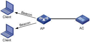
Client access
A client access process involves three steps: active/passive scanning surrounding wireless services, authentication, and association, as shown in Figure 1.
Figure 1 Establishing a client access
Scanning
Wireless clients can get the surrounding wireless network information in two ways, active scanning and passive scanning. With active scanning, a wireless client actively sends probe requests during scanning, and receives probe responses. With passive scanning, a wireless client listens to Beacon frames sent by surrounding APs.
A wireless client usually uses both passive scanning and active scanning to get information about surrounding wireless networks.
1. Active scanning
When a wireless client operates, it periodically searches for (that is, scans) surrounding wireless networks. Active scanning falls into two modes according to whether a specified SSID is carried in a probe request.
· Mode 1—A client sends a probe request without any SSID on supported channels to scan wireless networks. APs that receive the probe request frame send a probe response frame. The client associates with the AP with the strongest signal.
Figure 2 Active scanning (no SSID in the probe request)
· Mode 2—When a wireless client is configured to access a specific wireless network or has already been connected to a wireless network, the client periodically sends a probe request carrying the specified SSID. When an AP that can provide the wireless service with the specified SSID receives the probe request, it sends a probe response. This active scanning mode enables a client to access a specified wireless network. The active scanning process is as shown in Figure 3.
Figure 3 Active scanning (the probe request carries the specified SSID AP 1)
2. Passive scanning
Passive scanning is used by clients to discover surrounding wireless networks through listening to the beacon frames periodically sent by an AP. All APs providing wireless services periodically send beacons frames, so that wireless clients can listen to beacon frames on the supported channels to get information about surrounding wireless networks. Passive scanning is used by a client when it wants to save battery power. Typically, VoIP clients adopt the passive scanning mode. The passive scanning process is as shown in Figure 4.
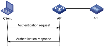
Authentication
To secure wireless links, the wireless clients must be authenticated before accessing an AP. 802.11 links define two authentication mechanisms: open system authentication and shared key authentication.
· Open system authentication
Open system authentication is the default authentication algorithm. This is the simplest of the available authentication algorithms. Essentially it is a null authentication algorithm. Any client that requests authentication with this algorithm can become authenticated. Open system authentication is not required to be successful as an AP may decline to authenticate the client. Open system authentication involves a two-step authentication process. In the first step, the wireless client sends a request for authentication. In the second step, the AP returns the result to the client.
Figure 5 Open system authentication process
· Shared key authentication
Figure 6 shows a shared key authentication process. The two parties have the same shared key configured.
a. The client sends an authentication request to the AP.
b. The AP randomly generates a challenge and sends it to the client.
c. The client uses the shared key to encrypt the challenge and sends it to the AP.
d. The AP uses the shared key to encrypt the challenge and compares the result with that received from the client. If they are identical, the client passes the authentication. If not, the authentication fails.
Figure 6 Shared key authentication process

Association
A client that wants to access a wireless network via an AP must be associated with that AP. Once the client chooses a compatible network with a specified SSID and authenticates to an AP, it sends an association request frame to the AP. The AP sends an association response to the client and adds the client's information in its database. At a time, a client can associate with only one AP. An association process is always initiated by the client, but not by the AP.
WLAN data security
Compared with wired networks, WLAN networks are more susceptible to attacks because all WLAN devices share the same medium and thus every device can receive data from any other sending device. If no security service is provided, plain-text data is transmitted over the WLAN.
To secure data transmission, 802.11 protocols provide some encryption methods to ensure that devices without the right key cannot read encrypted data.
1. WEP encryption
Wired Equivalent Privacy (WEP) was developed to protect data exchanged among authorized users in a wireless LAN from casual eavesdropping. WEP uses RC4 encryption (a stream encryption algorithm) for confidentiality. WEP encryption falls into static and dynamic encryption according to how a WEP key is generated.
· Static WEP encryption
With Static WEP encryption, all clients using the same SSID must use the same encryption key. If the encryption key is deciphered or lost, attackers will get all encrypted data. In addition, periodical manual key update brings great management workload.
· Dynamic WEP encryption
Dynamic WEP encryption is a great improvement over static WEP encryption. With dynamic WEP encryption, WEP keys are negotiated between client and server through the 802.1X protocol so that each client is assigned a different WEP key, which can be updated periodically to further improve unicast frame transmission security.
Although WEP encryption increases the difficulty of network interception and session hijacking, it still has weaknesses due to limitations of RC4 encryption algorithm and static key configuration.
2. TKIP encryption
Temporal key integrity Protocol (TKIP) and WEP both use the RC4 algorithm, but TKIP has many advantages over WEP, and provides more secure protection for WLAN as follows:
¡ First, TKIP provides longer IVs to enhance encryption security. Compared with WEP encryption, TKIP encryption uses 128–bit RC4 encryption algorithm, and increases the length of IVs from 24 bits to 48 bits.
¡ Second, TKIP allows for dynamic key negotiation to avoid static key configuration. TKIP replaces a single static key with a base key generated by an authentication server. TKIP dynamic keys cannot be easily deciphered.
¡ Third, TKIP offers Message Integrity Check (MIC) and countermeasures. If a packet fails the MIC, the data may be tampered, and the system may be attacked. If two packets fail the MIC in a certain period, the AP automatically takes countermeasures. It will not provide services in a certain period to prevent attacks.
3. CCMP encryption
CTR with CBC-MAC protocol (CCMP) is based on the CCM of the AES encryption algorithm. CCM combines CTR for confidentiality and CBC-MAC for authentication and integrity. CCM protects the integrity of both the MPDU Data field and selected portions of the IEEE 802.11 MPDU header. The AES block algorithm in CCMP uses a 128-bit key and a 128-bit block size. Similarly, CCMP contains a dynamic key negotiation and management method, so that each wireless client can dynamically negotiate a key suite, which can be updated periodically to further enhance the security of the CCMP encryption mechanism. During the encryption process, CCMP uses a 48-bit packet number (PN) to ensure that each encrypted packet uses a different PN, thus improving the security to a certain extent.
Client access authentication
1. PSK authentication
To implement PSK authentication, the client and the authenticator must have the same shared key configured. Otherwise, the client cannot pass pre-shared key (PSK) authentication.
2. 802.1X authentication
As a port-based access control protocol, 802.1X authenticates and controls accessing devices at the port level. A device connected to an 802.1X-enabled port of a WLAN access control device can access the resources on the WLAN only after passing authentication.
The administrators of access devices can select to use RADIUS or local authentication to cooperate with 802.1X for authenticating users. For more information about remote/local 802.1X authentication, see "802.1X configuration."
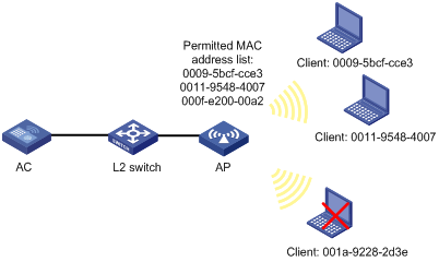
3. MAC authentication
MAC authentication provides a way for authenticating users based on ports and MAC addresses. You can configure permitted MAC address lists to filter MAC addresses of clients. However, the efficiency will be reduced when the number of clients increases. Therefore, MAC authentication is applicable to environments without high security requirements, for example, SOHO and small offices.
MAC authentication falls into two modes:
¡ Local MAC authentication—When this authentication mode is adopted, you need to configure a permitted MAC address list on the device. If the MAC address of a client is not in the list, its access request will be denied.
Figure 7 Local MAC authentication
¡ Remote MAC authentication—Remote Authentication Dial-In User Service (RADIUS) based MAC authentication. If the device finds that the current client is an unknown client, it sends an unsolicited authentication request to the RADIUS server. After the client passes the authentication, the client can access the WLAN network and the corresponding authorized information.
Figure 8 Remote MAC authentication
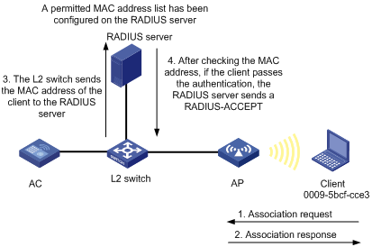
When a RADIUS server is used for MAC authentication, you can specify a domain for each wireless service, and thus send MAC authentication information of different SSIDs to different remote RADIUS servers.
802.11n
As the next generation wireless LAN technology, 802.11n supports both 2.4GHz and 5GHz bands. It provides higher throughput to customers by using the following methods:
1. Increasing bandwidth: 802.11n can bond two adjacent 20-MHz channels together to form a 40-MHz channel. During data forwarding, the two 20-MHz channels can work separately with one acting as the primary channel and the other acting as the secondary channel or work together as a 40-MHz channel. This provides a simple way of doubling the data rate.
2. Improving channel utilization through the following ways:
¡ 802.11n introduces the A-MPDU frame format. By using only one PHY header, each A-MPDU can accommodate multiple Message Protocol Data Units (MPDUs) which have their PHY headers removed. This reduces the overhead in transmission and the number of ACK frames to be used, and thus improves network throughput.
¡ Similar with MPDU aggregation, multiple MAC Service Data Units (MSDU) can be aggregated into a single A-MSDU. This reduces the MAC header overhead and thus improves MAC layer forwarding efficiency.
¡ To improve physical layer performance, 802.11n introduces the short GI function, which shortens the GI interval of 800 us in 802.11a/g to 400 us. This can increase the data rate by 10 percent.
Configuring access service
Recommended configuration procedure
|
Step |
Remarks |
|
Required. |
|
|
2. Configuring wireless service |
Required. Use either approach. Complete the security settings as needed. |
|
Required. |
|
|
Required. |
|
|
Optional. |
|
|
6. Displaying the detailed information of a wireless service |
Optional. |
Creating a WLAN service
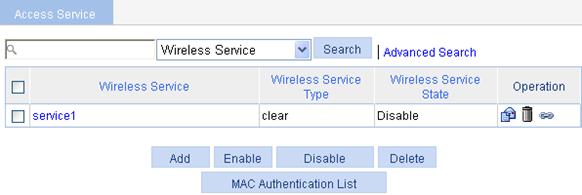
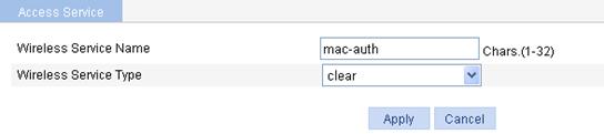
1. Select Wireless Service > Access Service from the navigation tree.
Figure 9 Configuring access service
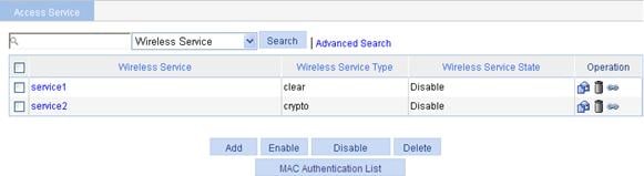
2. Click Add.
Figure 10 Creating a wireless service
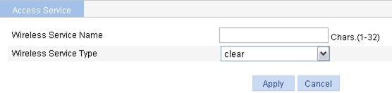
3. Configure the wireless service as described in Table 1.
4. Click Apply.
|
Item |
Description |
|
Wireless Service Name |
Set the Service Set Identifier (SSID), a case-sensitive string of 1 to 32 characters, which can include letters, digits, underlines, and spaces. An SSID should be as unique as possible. For security, the company name should not be contained in the SSID. Meanwhile, it is not recommended to use a long random string as the SSID, because a long random string only adds payload to the header field, without any improvement to wireless security. |
|
Wireless Service Type |
Select the wireless service type: · clear—Indicates the SSID will not be encrypted. · crypto—Indicates the SSID will be encrypted. |
Configuring clear type wireless service
Configuring basic settings for a clear type wireless service
|
|
NOTE: Before configuring a clear-type wireless service, disable it first and then click
the corresponding |
1. Select Wireless Service > Access Service from the navigation tree.
2.
Click the ![]() icon corresponding to the target clear type
wireless service to enter the page for configuring
wireless service.
icon corresponding to the target clear type
wireless service to enter the page for configuring
wireless service.
Figure 11 Configuring clear type wireless service
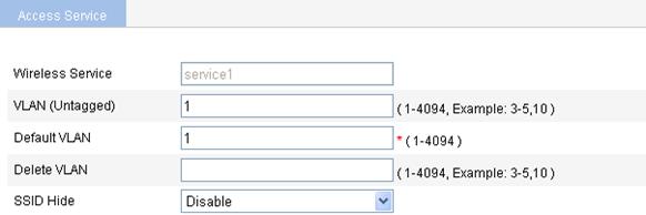
3. Configure basic settings for the clear type wireless service as described in Table 2.
4. Click Apply.
|
Item |
Description |
|
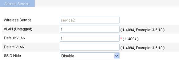
Wireless Service |
Display the selected Service Set Identifier (SSID). |
|
VLAN (Untagged) |
Enter the ID of the VLAN whose packets are to be sent untagged. VLAN (Untagged) indicates that the port sends the traffic of the VLAN with the VLAN tag removed. |
|
Default VLAN |
Set the default VLAN of a port. By default, the default VLAN of all ports is VLAN 1. After you set the new default VLAN, VLAN 1 is the ID of the VLAN whose packets are to be sent untagged. |
|
Delete VLAN |
Remove the IDs of the VLANs whose packets are to be sent untagged and tagged. |
|
SSID HIDE |
· Enable—Disable the advertisement of the SSID in beacon frames. · Disable—Enable the advertisement of the SSID in beacon frames. By default, the SSID is advertised in beacon frames.
· If the advertising of the SSID in beacon frames is disabled, the SSID must be configured for the clients to associate with the AP. · Disabling the advertising of the SSID in beacon frames does little good to wireless security. Allowing the advertising of the SSID in beacon frames enables a client to discover an AP more easily. |
Configuring advanced settings for the clear type wireless service
1. Select Wireless Service > Access Service from the navigation tree.
2.
Click the ![]() icon corresponding to the target clear type
wireless service to enter the page for configuring advanced settings for a clear type wireless service.
icon corresponding to the target clear type
wireless service to enter the page for configuring advanced settings for a clear type wireless service.
Figure 12 Advanced settings for the clear type wireless service
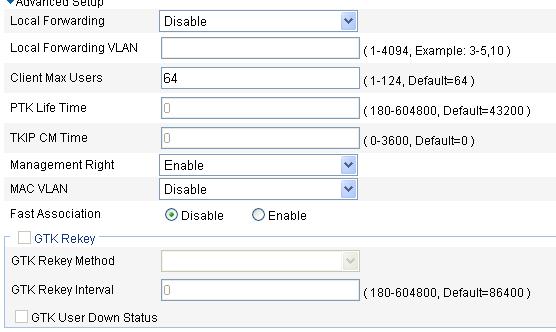
3. Configure advanced settings for the clear type wireless service as described in Table 3.
4. Click Apply.
|
Item |
Description |
|
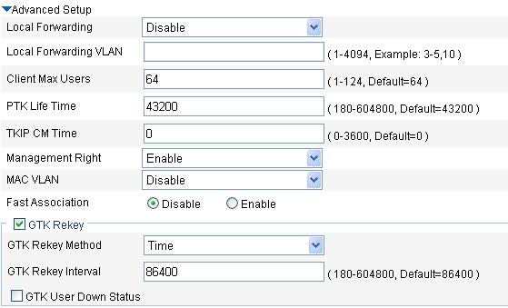
Local Forwarding |
Local forwarding enables an AP to forward data frames between clients. In a centralized WLAN architecture, an AP transparently transmits data frames to an AC for processing. With the increase of clients, the forwarding load of the AC increases either. With local forwarding enabled, an AP, rather the AC forwards client data, greatly reducing the load of the AC. · Enable—If local forwarding is enabled, data frames from an associated station will be forwarded by the AP itself. · Disable—If local forwarding is disabled, data frames from an associated station will be handled by the AC. |
|
Local Forwarding VLAN |
Clients using the same SSID may belong to different VLANs. You can configure a local forwarding VLAN when configuring a local forwarding policy. |
|
Client Max Users |
Maximum number of clients of an SSID to be associated with the same radio of the AP.
When the number of clients of an SSID to be associated with the same radio of the AP reaches the maximum, the SSID is automatically hidden. |
|
Management Right |
Web interface management right of online clients. · Disable—Disable the web interface management right of online clients. · Enable—Enable the web interface management right of online clients. |
|
MAC VLAN |
· Enable—Enable the MAC VLAN feature for the wireless service. · Disable—Disable the MAC VLAN feature for the wireless service.
Before binding an AP radio to a VLAN, a step of enabling AP-based access VLAN recognition, enable the MAC VLAN feature first. |
|
Fast Association |
· Enable—Enable fast association. · Disable—Disable fast association. By default, fast association is disabled. When fast association is enabled, the device does not perform band navigation and load balancing calculations for associated clients. |
Configuring security settings for a clear type wireless service
1. Select Wireless Service > Access Service from the navigation tree.
2.
Click the ![]() icon corresponding to the target clear type wireless service to enter the page for
configuring security settings for the clear type wireless service.
icon corresponding to the target clear type wireless service to enter the page for
configuring security settings for the clear type wireless service.
Figure 13 Security settings for the clear-type wireless service
3. Configure security settings for the clear type wireless service as described in Table 4.
4. Click Apply.
|
Item |
Description |
|
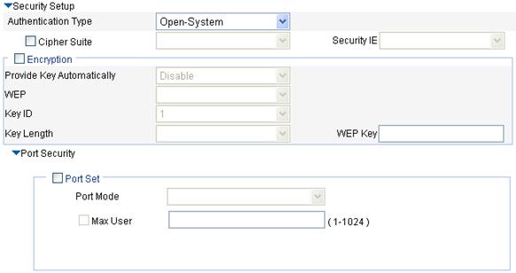
Authentication Type |
For the clear type wireless service, you can select Open-System only. |
|
Port Mode |
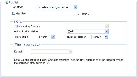
· mac-authentication—Perform MAC address authentication on users. · mac-else-userlogin-secure—This mode is the combination of the mac-authentication and userlogin-secure modes, with MAC authentication having a higher priority. Upon receiving a non-802.1X frame, a port in this mode performs only MAC authentication; upon receiving an 802.1X frame, the port performs MAC authentication and then, if MAC authentication fails, 802.1X authentication. · mac-else-userlogin-secure-ext—This mode is similar to the mac-else-userlogin-secure mode, except that it supports multiple 802.1X and MAC authentication users on the port. · userlogin-secure—In this mode, MAC-based 802.1X authentication is performed for users; multiple 802.1X authenticated users can access the port, but only one user can be online. · userlogin-secure-or-mac—This mode is the combination of the userlogin-secure and mac-authentication modes, with 802.1X authentication having a higher priority. For a wireless user, 802.1X authentication is performed first. If 802.1X authentication fails, MAC authentication is performed. · userlogin-secure-or-mac-ext—This mode is similar to the userlogin-secure-or-mac mode, except that it supports multiple 802.1X and MAC authentication users on the port. · userlogin-secure-ext—In this mode, a port performs 802.1X authentication on users in macbased mode and supports multiple 802.1X users.
There are multiple security modes. To remember them easily, follow these rules to understand part of the port security mode names: · userLogin indicates port-based 802.1X authentication. · mac indicates MAC address authentication. · The authentication mode before Else is used preferentially. If the authentication fails, the authentication after Else may be used depending on the protocol type of the packets to be authenticated. · The authentication mode before Or and that after Or have the same priority. The device determines the authentication mode according to the protocol type of the packets to be authenticated. For wireless users, the 802.1X authentication mode is used preferentially. · userLogin together with Secure indicates MAC-based 802.1X authentication. · A security mode with Ext allows multiple 802.1X users to pass the authentication. A security mode without Ext allows only one 802.1X user to pass the authentication. |
|
Max User |
Maximum number of users that can be connected to the network through a specific port. |
a. Configure mac-authentication
Figure 14 mac-authentication port security configuration page
|
Item |
Description |
|
Port Mode |
mac-authentication—MAC-based authentication is performed on access users. Select Wireless Service > Access Service from the navigation tree, click MAC Authentication List, and enter the MAC address of the client. |
|
Max User |
Control the maximum number of users allowed to access the network through the port. |
|
MAC Authentication |
Select MAC Authentication. |
|
Domain |
Select an existing domain from the list. The default domain is system. To create a domain, select Authentication > AAA from the navigation tree, click the Domain Setup tab, and enter a new domain name in the Domain Name field. · The selected domain name applies to only the current wireless service, and all clients accessing the wireless service use this domain for authentication, authorization, and accounting. · Do not delete a domain name in use. Otherwise, the clients that access the wireless service will be logged out. |
b. Configure userlogin-secure/userlogin-secure-ext
Figure 15 userlogin-secure/userlogin-secure-ext port security configuration page (userlogin-secure is taken for example)
|
Item |
Description |
|
Port Mode |
· userlogin-secure—Perform MAC-based 802.1X authentication for access users. In this mode, multiple 802.1X authenticated users can access the port, but only one user can be online. · userlogin-secure-ext—Perform MAC-based 802.1X authentication for access users. In this mode, the port supports multiple 802.1X users. |
|
Max User |
Control the maximum number of users allowed to access the network through the port. |
|
Mandatory Domain |
Select an existing domain from the list. The default domain is system. To create a domain, select Authentication > AAA from the navigation tree, click the Domain Setup tab, and enter a new domain name in the Domain Name field. · The selected domain name applies to only the current wireless service, and all clients accessing the wireless service use this domain for authentication, authorization, and accounting. · Do not delete a domain name in use. Otherwise, the clients that access the wireless service will be logged out. |
|
Authentication Method |
· EAP—Use the Extensible Authentication Protocol (EAP). With EAP authentication, the authenticator encapsulates 802.1X user information in the EAP attributes of RADIUS packets and sends the packets to the RADIUS server for authentication; it does not need to repackage the EAP packets into standard RADIUS packets for authentication. · CHAP—Use the Challenge Handshake Authentication Protocol (CHAP). By default, CHAP is used. CHAP transmits usernames in simple text and passwords in cipher text over the network. Therefore this method is safer. · PAP—Use the Password Authentication Protocol (PAP). PAP transmits passwords in plain text. |
|
Handshake |
· Enable—Enable the online user handshake function so that the device can periodically send handshake messages to a user to check whether the user is online. By default, the function is enabled. · Disable—Disable the online user handshake function. |
|
Multicast Trigger |
· Enable—Enable the multicast trigger function of 802.1X to send multicast trigger messages to the clients periodically for initiating authentication. By default, the multicast trigger function is enabled. · Disable—Disable the 802.1X multicast trigger function.
For a WLAN, the clients can actively initiate authentication, or the AP can discover users and trigger authentication. Therefore, the ports do not need to send 802.1X multicast trigger messages for initiating authentication periodically. H3C recommends that you disable the multicast trigger function in a WLAN because the multicast trigger messages consume bandwidth. |
c. Configure the other four port security modes
Figure 16 Port security configuration page for the other four security modes (mac-else-userlogin-secure is taken for example)
|
Item |
Description |
|
Port Mode |
· mac-else-userlogin-secure—This mode is the combination of the mac-authentication and userlogin-secure modes, with MAC authentication having a higher priority. Upon receiving a non-802.1X frame, a port in this mode performs only MAC authentication; upon receiving an 802.1X frame, the port performs MAC authentication and then, if MAC authentication fails, 802.1X authentication. · mac-else-userlogin-secure-ext—This mode is similar to the mac-else-userlogin-secure mode, except that it supports multiple 802.1X and MAC authentication users on the port. · userlogin-secure-or-mac—This mode is the combination of the userlogin-secure and mac-authentication modes, with 802.1X authentication having a higher priority. For a wireless user, 802.1X authentication is performed first. If 802.1X authentication fails, MAC authentication is performed. · userlogin-secure-or-mac-ext—This mode is similar to the userlogin-secure-or-mac mode, except that it supports multiple 802.1X and MAC authentication users on the port. Select Wireless Service > Access Service from the navigation tree, click MAC Authentication List, and enter the MAC address of the client. |
|
Max User |
Control the maximum number of users allowed to access the network through the port. |
|
Mandatory Domain |
Select an existing domain from the list. After a mandatory domain is configured, all 802.1X users accessing the port are forced to use the mandatory domain for authentication, authorization, and accounting. The default domain is system. To create a domain, select Authentication > AAA from the navigation tree, click the Domain Setup tab, and enter a new domain name in the Domain Name field. |
|
Authentication Method |
· EAP—Use the Extensible Authentication Protocol (EAP). With EAP authentication, the authenticator encapsulates 802.1X user information in the EAP attributes of RADIUS packets and sends the packets to the RADIUS server for authentication; it does not need to repackage the EAP packets into standard RADIUS packets for authentication. · CHAP—Use the Challenge Handshake Authentication Protocol (CHAP). By default, CHAP is used. CHAP transmits usernames in simple text and passwords in cipher text over the network. Therefore this method is safer. · PAP—Use the Password Authentication Protocol (PAP). PAP transmits passwords in plain text. |
|
Handshake |
· Enable—Enable the online user handshake function so that the device can periodically send handshake messages to a user to check whether the user is online. By default, the function is enabled. · Disable—Disable the online user handshake function. |
|
Multicast Trigger |
· Enable—Enable the multicast trigger function of 802.1X to send multicast trigger messages to the clients periodically for initiating authentication. By default, the multicast trigger function is enabled. · Disable—Disable the 802.1X multicast trigger function.
For a WLAN, the clients can actively initiate authentication, or the AP can discover users and trigger authentication. Therefore, the ports do not need to send 802.1X multicast trigger messages periodically for initiating authentication. You are recommended to disable the multicast trigger function in a WLAN because the multicast trigger messages consume bandwidth. |
|
MAC Authentication |
Select MAC Authentication. |
|
Domain |
Select an existing domain from the list. The default domain is system. To create a domain, select Authentication > AAA from the navigation tree, click the Domain Setup tab, and enter a new domain name in the Domain Name field. · The selected domain name applies to only the current wireless service, and all clients accessing the wireless service use this domain for authentication, authorization, and accounting. · Do not delete a domain name in use. Otherwise, the clients that access the wireless service will be logged out. |
Configuring crypto type wireless service
Configuring basic settings for a crypto type wireless service
1. Select Wireless Service > Access Service from the navigation tree.
2.
Click the ![]() icon corresponding to the target crypto type wireless service to enter the page for
configuring wireless service.
icon corresponding to the target crypto type wireless service to enter the page for
configuring wireless service.
Figure 17 Crypto type wireless service
3. Configure basic settings for the crypto type wireless service as described in Table 2.
4. Click Apply.
Configuring advanced settings for a crypto type wireless service
1. Select Wireless Service > Access Service from the navigation tree.
2.
Click the ![]() icon corresponding to the target crypto type wireless service to enter the page for
configuring wireless service.
icon corresponding to the target crypto type wireless service to enter the page for
configuring wireless service.
Figure 18 Advanced settings for the crypto type wireless service
3. Configure advanced settings for the crypto type wireless service as described in Table 8.
4. Click Apply.
|
Item |
Description |
|
Local Forwarding |
Local forwarding enables an AP to forward data frames between clients. In a centralized WLAN architecture, an AP transparently transmits data frames to an AC for processing. With the increase of clients, the forwarding load of the AC increases either. With local forwarding enabled, an AP, rather the AC, forwards client data, greatly reducing the load of the AC. · Enable—If local forwarding is enabled, data frames from an associated station will be forwarded by the AP itself. · Disable—If local forwarding is disabled, data frames from an associated station will be handled by the AC. |
|
Local Forwarding VLAN |
Clients using the same SSID may belong to different VLANs. You can configure a local forwarding VLAN when configuring a local forwarding policy. |
|
Client Max Users |
Maximum number of clients of an SSID to be associated with the same radio of the AP.
When the number of clients of an SSID to be associated with the same radio of the AP reaches the maximum, the SSID is automatically hidden. |
|
PTK Life Time |
Set the pairwise transient key (PTK) lifetime. A PTK is generated through a four-way handshake. |
|
TKIP CM Time |
Set the TKIP countermeasure time. By default, the TKIP countermeasure time is 0 seconds, that is, the TKIP countermeasure policy is disabled. Message integrity check (MIC) is designed to avoid hacker tampering. It uses the Michael algorithm and is extremely secure. When failures occur to MIC, the data may have been tampered, and the system may be under attack. With the countermeasure policy enabled, if more than two MIC failures occur within the specified time, the TKIP associations are disassociated and no new associations are allowed within the TKIP countermeasure time. |
|
Management Right |
Web interface management right of online clients. · Disable—Disable the web interface management right of online clients. · Enable—Enable the web interface management right of online clients. |
|
MAC VLAN |
· Enable—Enable the MAC VLAN feature for the wireless service. · Disable—Disable the MAC VLAN feature for the wireless service.
Before you bind an AP radio to a VLAN, a step of enabling AP-based access VLAN recognition, enable the MAC VLAN feature first. |
|
Fast Association |
· Enable—Enable fast association. · Disable—Disable fast association. By default, fast association is disabled. When fast association is enabled, the device does not perform band navigation and load balancing calculations for associated clients. |
|
GTK Rekey Method |
An AC generates a group transient key (GTK) and sends the GTK to a client during the authentication process between an AP and the client through group key handshake/the 4-way handshake. The client uses the GTK to decrypt broadcast and multicast packets. · If Time is selected, the GTK will be refreshed after a specified period of time. · If Packet is selected, the GTK will be refreshed after a specified number of packets are transmitted. By default, the GTK rekeying method is time-based, and the interval is 86400 seconds. |
|
GTK User Down Status |
Enable refreshing the GTK when some client goes offline. By default, the GTK is not refreshed when a client goes off-line. |
Configuring security settings for a crypto type wireless service
1. Select Wireless Service > Access Service from the navigation tree.
2.
Click the ![]() icon corresponding to the target crypto type wireless service to enter the page for
configuring crypto type wireless service.
icon corresponding to the target crypto type wireless service to enter the page for
configuring crypto type wireless service.
Figure 19 Security settings for the crypto type wireless service
3. Configure security settings for the crypto type wireless service as described in Table 9.
4. Click Apply.
|
Item |
Description |
|
Authentication Type |
· Open-System—No authentication. With this authentication mode enabled, all the clients will pass the authentication. · Shared-Key—The two parties need to have the same shared key configured for this authentication mode. You can select this option only when WEP encryption mode is used. · Open-System and Shared-Key—It indicates that you can select both open-system and shared-key authentication.
WEP encryption can be used together with open system and shared-key authentication. · Open system authentication—When this authentication mode is used, a WEP key is used for encryption only. If the two parities do not use the same key, a wireless link can still be established, but all data will be discarded. · Shared-key authentication—When this authentication mode is used, a WEP key is used for both authentication and encryption. If the two parties do not use the same key, the client cannot pass the authentication, and thus cannot access the wireless network. |
|
Cipher Suite |
Encryption mechanisms supported by the wireless service, which can be: · AES-CCMP—Encryption mechanism based on the AES encryption algorithm. · TKIP—Encryption mechanism based on the RC4 algorithm and dynamic key management. · AES-CCMP and TKIP—It indicates that you can select both CCMP and TKIP encryption. |
|
Security IE |
Wireless service type (IE information carried in the beacon or probe response frame): · WPA—Wi-Fi Protected Access. · RSN—An RSN is a security network that allows only the creation of robust security network associations (RSNAs). It provides greater protection than WEP and WPA. · WPA and RSN—It indicates that you can select both WPA and RSN.. |
|
Encryption |
|
|
Provide Key Automatically |
· Enable—A WEP key is dynamically assigned. · Disable—A static WEP key is used. By default, a static WEP key is used. When you enable this function, the WEP option is automatically set to wep104.
· This function must be used together with 802.1X authentication. · With dynamic WEP encryption configured, the WEP key used to encrypt unicast frames is negotiated between client and server. If the WEP default key is configured, the WEP default key is used to encrypt multicast frames. If not, the device randomly generates a multicast WEP key. |
|
WEP |
· wep40—Indicates the WEP40 key option. · wep104—Indicates the WEP104 key option. · wep128—Indicates the WEP128 key option. |
|
Key ID |
· 1—Key index 1. · 2—Key index 2. · 3—Key index 3. · 4—Key index 4. There are 4 static keys in WEP. The key index can be 1, 2, 3 or 4. The key corresponding to the specified key index will be used for encrypting and decrypting broadcast and multicast frames. |
|
Key Length |
Key length. · For wep40, the key is a string of 5 alphanumeric characters or a 10-digit hexadecimal number. · For wep104, the key is a string of 13 alphanumeric characters or a 26-digit hexadecimal number. · For wep128, the key is a string of 16 alphanumeric characters or a 32-digit hexadecimal number. |
|
WEP Key |
Configure the WEP key. |
|
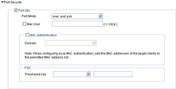
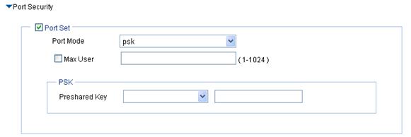
Port Security |
See Table 4. Parameters such as authentication type and encryption type determine the port mode. For more information, see Table 12. After you select the Cipher Suite option, the following three port security modes are added: · mac and psk—MAC-based authentication must be performed on access users first. If MAC-based authentication succeeds, an access user has to use the pre-configured PSK to negotiate with the device. Access to the port is allowed only after the negotiation succeeds. · psk—An access user must use the pre-shared key (PSK) that is pre-configured to negotiate with the device. The access to the port is allowed only after the negotiation succeeds. · userlogin-secure-ext—Perform MAC-based 802.1X authentication for access users. In this mode, the port supports multiple 802.1X users. |
a. Configure mac and psk
Figure 20 mac and psk port security configuration page
|
Item |
Description |
|
Port Mode |
mac and psk: MAC-based authentication must be performed on access users first. If MAC-based authentication succeeds, an access user has to use the pre-configured PSK to negotiate with the device. Access to the port is allowed only after the negotiation succeeds. Select Wireless Service > Access Service from the navigation tree, click MAC Authentication List, and enter the MAC address of the client. |
|
Max User |
Control the maximum number of users allowed to access the network through the port. |
|
MAC Authentication |
Select MAC Authentication. |
|
Domain |
Select an existing domain from the list. The default domain is system. To create a domain, select Authentication > AAA from the navigation tree, click the Domain Setup tab, and enter a new domain name in the Domain Name field. · The selected domain name applies to only the current wireless service, and all clients accessing the wireless service use this domain for authentication, authorization, and accounting. · Do not delete a domain name in use. Otherwise, the clients that access the wireless service will be logged out. |
|
Pre-shared Key |
· pass-phrase—Enter a PSK in the form of a character string. You must enter a string that can be displayed and is of 8 to 63 characters. · raw-key—Enter a PSK in the form of a hexadecimal number. You must enter a valid 64-bit hexadecimal number. |
b. Configure psk
Figure 21 psk port security configuration page
|
Item |
Description |
|
Port Mode |
psk—An access user must use the pre-shared key (PSK) that is pre-configured to negotiate with the device. The access to the port is allowed only after the negotiation succeeds. |
|
Max User |
Control the maximum number of users allowed to access the network through the port. |
|
Pre-shared Key |
· pass-phrase—Enter a PSK in the form of a character string. You must enter a string that can be displayed and is of 8 to 63 characters. · raw-key—Enter a PSK in the form of a hexadecimal number. You must enter a valid 64-bit hexadecimal number. |
c. Configure userlogin-secure-ext
Perform the configurations as shown in Configure userlogin-secure/userlogin-secure-ext.
Security parameter dependencies
For a clear-type wireless service or crypto-type wireless service, the security parameter dependencies are as shown in Table 12.
Table 12 Security parameter dependencies
|
Service type |
Authentication mode |
Encryption type |
Security IE |
WEP encryption/key ID |
Port mode |
|
Clear |
Open-System |
Unavailable |
Unavailable |
Unavailable |
· mac-authentication · mac-else-userlogin-secure · mac-else-userlogin-secure-ext · userlogin-secure · userlogin-secure-ext · userlogin-secure-or-mac · userlogin-secure-or-mac-ext |
|
Crypto |
Open-System |
Selected |
Required |
WEP encryption is available The key ID can be 2, 3, or 4. |
· mac and psk · psk · userlogin-secure-ext |
|
Unselected |
Unavailable |
WEP encryption is required The key ID can be 1, 2, or 3. |
· mac-authentication · userlogin-secure · userlogin-secure-ext |
||
|
Shared-Key |
Unavailable |
Unavailable |
WEP encryption is required The key ID can be 1, 2, 3 or 4. |
mac-authentication |
|
|
Open-System and Shared-Key |
Selected |
Required |
WEP encryption is required The key ID can be 1, 2, 3 or 4. |
· mac and psk · psk · userlogin-secure-ext |
|
|
Unselected |
Unavailable |
WEP encryption is required The key ID can be 1, 2, 3 or 4. |
· mac-authentication · userlogin-secure · userlogin-secure-ext |
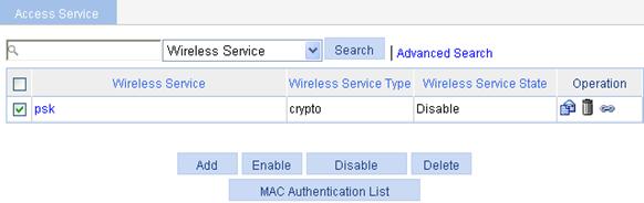
Enabling a wireless service
1. Select Wireless Service > Access Service from the navigation tree.
Figure 22 Enabling a wireless service
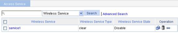
2. Select the wireless service to be bound.
3. Click Enable.
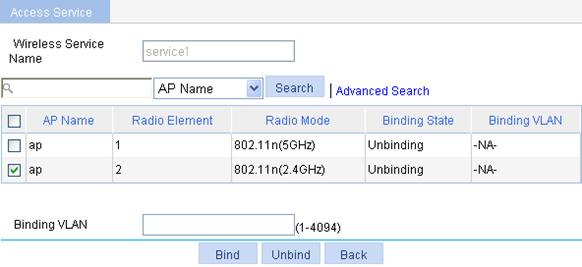
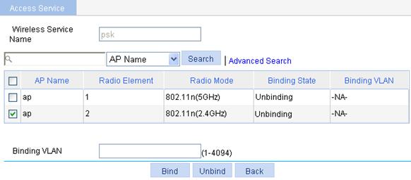
Binding an AP radio to a wireless service
Binding an AP radio to a wireless service
1. Select Wireless Service > Access Service from the navigation tree.
2.
Click the ![]() icon corresponding to the target wireless service
to enter the page for binding an AP radio to a wireless service.
icon corresponding to the target wireless service
to enter the page for binding an AP radio to a wireless service.
Figure 23 Binding an AP radio to a wireless service
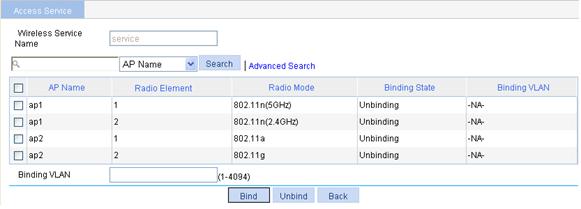
3. Select the AP radio to be bound.
4. Click Bind.
A configuration progress dialog box appears.
5. After the configuration process is complete, click Close.
Binding an AP radio to a VLAN
Traffic of different services is identified by SSIDs. Locations are identified by APs. Users at different locations access different services. For a user roaming between different APs, you can provide services for the user based on its access AP. The detailed requirements are as follows:
· Users with the same SSID but accessing through different APs can be assigned to different VLANs based on their configurations.
· A roaming user always belongs to the same VLAN.
· For a user roaming between ACs, if the local AC does not have a VLAN-interface, the user needs to use an HA in the AC group for forwarding packets to avoid packet loss.
Figure 24 Schematic diagram for WLAN support for AP-based access VLAN recognition
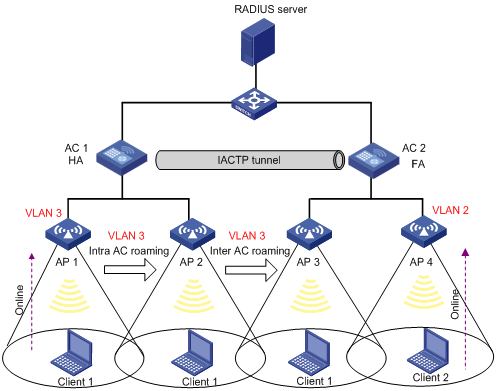
As shown in Figure 24, Client 1 goes online through AP 1 and belongs to VLAN 3. When Client 1 roams within an AC or between ACs, Client 1 always belongs to VLAN 3. When Client 1 roams between ACs, if FA, that is, AC 2, has VLAN-interface 3, AC 2 forwards packets from Client 1. Otherwise, packets from Client 1 are sent to HA (AC 1) through the data tunnel and then HA forwards these packets.
Client 2 goes online through AP 4 and belongs to VLAN 2. That is, a client going online through a different AP is assigned to a different VLAN.
1. Select Wireless Service > Access Service from the navigation tree.
2.
Click the ![]() icon corresponding
to the target wireless service to enter the AP radio
setup page, as shown in Figure 23.
icon corresponding
to the target wireless service to enter the AP radio
setup page, as shown in Figure 23.
3. Select the box corresponding to the AP radio mode to be bound.
4. Enter the VLAN to be bound in the Binding VLAN field.
5. Click Bind.
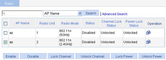
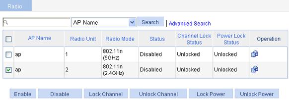
Enabling a radio
1. Select Radio > Radio from the navigation tree.
Figure 25 Enabling 802.11n radio
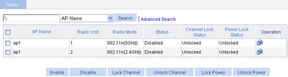
2. Select the box of the target radio.
3. Click Enable.
A configuration progress dialog box appears.
4. After the configuration process is complete, click Close.
Displaying the detailed information of a wireless service
Displaying the detailed information of a clear-type wireless service
1. Select Wireless Service > Access Service from the navigation tree.
2. Click the specified clear-type wireless service to see its detailed information.
Figure 26 Displaying the detailed information of a clear-type wireless service
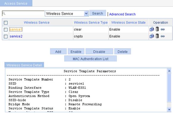
Table 13 Field description
|
Field |
Description |
|
Service Template Number |
Current service template number. |
|
SSID |
Service set identifier. |
|
Binding Interface |
Name of the WLAN-ESS interface bound with the service template. |
|
Service Template Type |
Service template type. |
|
Authentication Method |
Type of authentication used. A clear-type wireless service can use only Open System authentication. |
|
SSID-hide |
· Disable—Indicates that SSID advertisement is enabled. · Enable—Indicates that SSID advertisement is disabled, that is, the AP does not advertise the SSID in the beacon frames. |
|
Bridge Mode |
Forwarding mode, which can be: · Local Forwarding—Use the local forwarding mode. · Remote Forwarding—Use the remote forwarding mode, that is, uses the AC to forward data. |
|
Service Template Status |
Service template status, which can be: · Enable—Indicates that the wireless service is enabled. · Disable—Indicates that the wireless service is disabled. |
|
Maximum clients per BSS |
Maximum number of associated clients per BSS. |
Displaying the detailed information of a crypto-type wireless service
1. Select Wireless Service > Access Service from the navigation tree.
2. Click a crypto-type wireless service to see its detailed information.
Figure 27 Displaying the detailed information of a crypto-type wireless service
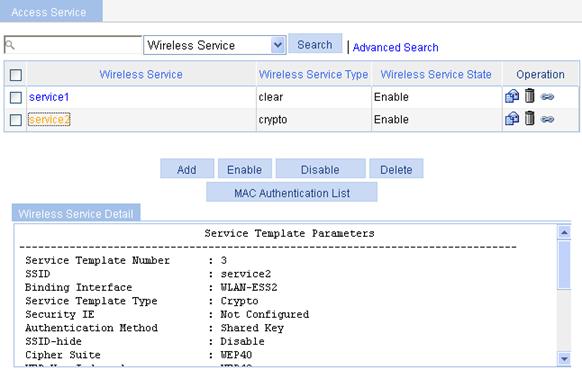
Table 14 Field description
|
Field |
Description |
|
Service Template Number |
Current service template number. |
|
SSID |
Service set identifier. |
|
Binding Interface |
Name of WLAN-ESS the interface bound with the service template. |
|
Service Template Type |
Service template type. |
|
Security IE |
Security IE, which can be WPA or WPA2. |
|
Authentication Method |
Type of authentication used, which can be Open System or Shared Key. |
|
SSID-hide |
· Disable—Indicates that SSID advertisement is enabled. · Enable—Indicates that SSID advertisement is disabled, that is, the AP does not advertise the SSID in the beacon frames. |
|
Cipher Suite |
Cipher suite, which can be CCMP, TKIP, or WEP40/WEP104/WEP128. |
|
WEP Key Index |
WEP key index for encryption or de-encryption frames. |
|
WEP Key Mode |
WEP key mode: · HEX—WEP key in hexadecimal format. · ASCII—WEP key in the format of string. |
|
WEP Key |
WEP key. |
|
TKIP Countermeasure Time(s) |
TKIP MIC failure holdtime, in seconds. |
|
PTK Life Time(s) |
PTK lifetime in seconds. |
|
GTK Rekey |
GTK rekey configured. |
|
GTK Rekey Method |
GTK rekey method configured, which can be: · Time-based, which displays the GTK rekey time in seconds. · Packet-based, which displays the number of packets. |
|
GTK Rekey Time |
Time for GTK rekey in seconds. |
|
Bridge Mode |
Forwarding mode, which can be: · Local Forwarding—Use the local forwarding mode. · Remote Forwarding—Use the remote forwarding mode, that is, uses the AC to forward data. |
|
Service Template Status |
Service template status, which can be: · Enable—Indicates that the wireless service is enabled. · Disable—Indicates that the wireless service is disabled. |
|
Maximum clients per BSS |
Maximum number of associated clients per BSS. |
Wireless service configuration example
Network requirements
As shown in Figure 28, an AP is required to enable employees to access the internal resources at any time. More specifically:
· An AC and the AP (serial ID 210235A29G007C000020) is connected through a Layer 2 switch.
· The AP provides clear type wireless access service with SSID service1.
· 802.11n (2.4GHz) radio mode is adopted.

Configuring the AC
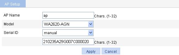
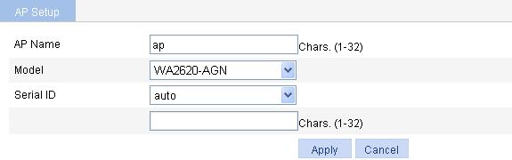
1. Create an AP:
a. Select AP > AP Setup from the navigation tree.
b. Click Add.
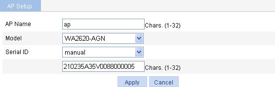
c. On the page that appears, set the AP name to ap, select the AP model WA2620-AGN, select the serial ID manual, and enter the serial ID of the AP.
d. Click Apply.
Figure 29 Creating an AP
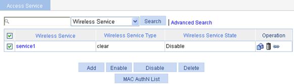
2. Configure a wireless service:
a. Select Wireless Service > Access Service from the navigation tree.
b. Click Add.
c. On the page that appears, set the service name to service1 and select the wireless service type clear.
d. Click Apply.
Figure 30 Creating a wireless service

3. Enable the wireless service:
a. Select Wireless Service > Access Service from the navigation tree.
b. On the page that appears, select the service1 box and click Enable.
Figure 31 Enabling wireless service
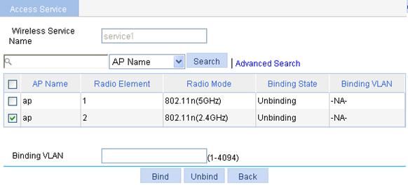
4. Bind an AP radio to a wireless service:
a. Select Wireless Service > Access Service from the navigation tree.
b. Click the ![]() icon corresponding to the wireless service
service1.
icon corresponding to the wireless service
service1.
c. On the page that appears, select the box before ap with radio type 802.11n(2.4GHz).
d. Click Bind.
Figure 32 Binding an AP radio
5. Enable 802.11n(2.4GHz) radio
a. Select Radio > Radio from the navigation tree.
b. Select the box before ap with the radio mode 802.11n(2.4GHz).
c. Click Enable.
Figure 33 Enabling 802.11n(2.4GHz) radio
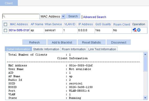
Verifying the configuration
· The client can successfully associate with the AP and access the WLAN network.
· You can view the online clients on the page that you enter by selecting Summary > Client from the navigation tree.
Figure 34 Viewing the online clients
Configuration guidelines
Select a correct district code.
Auto AP configuration example
Network requirements
As shown in Figure 35, enable the auto-AP function to enable APs to automatically connect to the AC.
· The AP provides a clear type wireless service with the SSID service1.
· 802.11n(2.4GHz) radio mode is adopted.

Configuring the AC
1. Create an AP:
a. Select AP > AP Setup from the navigation tree.
b. Click Add.
c. On the page that appears, set the AP name to ap, select the AP model WA2620-AGN, select the serial ID auto, and click Apply.
Figure 36 Creating an AP
2. Configure a wireless service:
a. Select Wireless Service > Access Service from the navigation tree.
b. Click Add.
c. On the page that appears, set the service name to service1, select the wireless service type clear, and click Apply.
Figure 37 Creating a wireless service
3. Enable the wireless service:
a. Select Wireless Service > Access Service from the navigation tree.
b. Select the service1 box.
c. Click Enable.
Figure 38 Enabling the wireless service
4. Bind an AP to a wireless service:
a. Select Wireless Service > Access Service from the navigation tree.
b. Click the ![]() icon corresponding to the wireless service service1.
icon corresponding to the wireless service service1.
c. On the page that appears, select the box before ap with radio mode 802.11n(2.4GHz), and click Bind.
Figure 39 Binding an AP
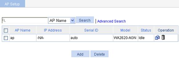
d. To view the AP status, select AP > AP Setup from the navigation tree. You can see that the AP is in IDLE state.
Figure 40 AP status before auto AP is enabled
5. Enable auto AP
a. Select AP > Auto AP from the navigation tree.
b. Select enable.
c. Click Apply.
Figure 41 Configuring auto AP

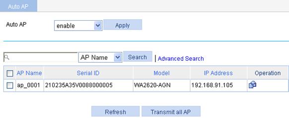
d. To view the automatically found AP (ap_0001), click Refresh.
Figure 42 Viewing the automatically found AP
6. Rename the automatically found AP
¡ If you do not need to rename the automatically found AP, select the ap_0001 box, and then click Transmit All AP.
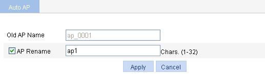
¡ To rename the automatically found AP:
a. Select AP > Auto AP from the navigation tree.
b. Click the ![]() icon of the target
AP.
icon of the target
AP.
c. On the page that appears, select AP Rename and enter ap1.
d. Click Apply.
Figure 43 Modifying the AP name
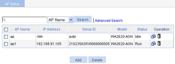
e. To view the renamed AP, select AP > AP Setup from the navigation tree.
Figure 44 Displaying AP
7. Enable 802.11n(2.4GHz) radio
a. Select Radio > Radio from the navigation tree.
b. Select the box of the target AP.
c. Click Enable.
Verifying the configuration
· You can see that the AP is in the Run state on the page you enter by selecting AP > AP Setup from the navigation tree.
· The client can successfully associate with the AP and access the WLAN network.
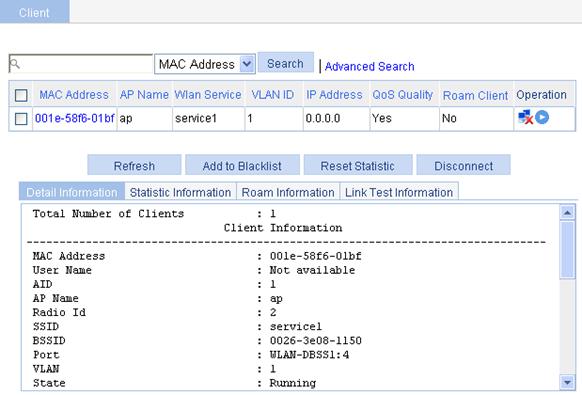
· You can view the online clients on the page that you enter by selecting Summary > Client from the navigation tree.
Figure 45 Viewing the online clients
Configuration guidelines
Follow these guidelines when you configure an auto AP:
· Select a correct district code.
· Select the renamed AP (AP 1 in the example) rather than the auto AP (ap in the example) when enabling the radio. If you enable the radio of the automatically found AP, the radios of all the automatically found APs are enabled.
802.11n configuration example
Network requirements
As shown in Figure 46, deploy an 802.11n network to provide high bandwidth access for multi-media applications.
· The AP provides a plain-text wireless service with SSID service.
· 802.11gn is adopted to inter-work with the existing 802.11g network and protect the current investment.

Configuring the AC
1. Create an AP:
a. Select AP > AP Setup from the navigation tree.
b. Click Add.
c. On the page that appears, set the AP name to 11nap, select the AP model WA22610E-AGN, select the serial ID manual, enter the serial ID of the AP, and click Apply.
2. Create a wireless service:
a. Select Wireless Service > Access Service from the navigation tree.
b. Click Add.
c. On the page that appears, set the service name to 11nservice, select the wireless service type clear, and click Apply.
3. Enable wireless service:
a. Select Wireless Service > Access Service from the navigation tree.
b. Select the 11nservice box.
c. Click Enable.
4. Bind an AP radio:
a. Select Wireless Service > Access Service from the navigation tree.
b. Click the ![]() icon corresponding to the target wireless service.
icon corresponding to the target wireless service.
c. Select the 11nap box.
d. Click Bind.
5. Enable 802.11n(2.4GHZ) radio:
a. Select Radio > Radio from the navigation tree.
b. Select the 11nap box of the target AP.
c. Click Enable.
Verifying the configuration
· The client can successfully associate with the AP and access the WLAN network.
· You can view the online clients on the page you enter by selecting Summary > Client from the navigation tree.
Figure 47 Viewing the online clients
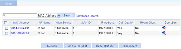
In this example, 0014-6c8a-43ff is an 802.11g user, and 001c-f0bf-9c92 is an 802.11n user. Both of the two users can access the WLAN network because there is no limit on the user type. If you enable client 802.11n only, only 001c-f0bf-9c92 can access the WLAN network.
Configuration guidelines
Follow these guidelines when you configure 802.11n:
·
Select Radio > Radio from the navigation
tree, select the AP to be configured, and click ![]() to enter the page for configuring a radio. Then you can modify the
802.11n parameters, including bandwidth mode, A-MPDU, A-MSDU, short GI and
whether 802.11n clients are allowed.
to enter the page for configuring a radio. Then you can modify the
802.11n parameters, including bandwidth mode, A-MPDU, A-MSDU, short GI and
whether 802.11n clients are allowed.
· Select Radio > Rate from the navigation tree to set 802.11n rates.
WPA-PSK authentication configuration example
Network requirements
As shown in Figure 48, connect the client to the wireless network through WPA-PSK authentication. The PSK key configuration on the client is the same as that on the AC: 12345678.
Configuring the AC
1. Create an AP:
a. Select AP > AP Setup from the navigation tree.
b. Click Add.
c. On the page that appears, set the AP name to ap, select the AP model WA2620-AGN, select the serial ID manual, enter the AP serial ID, and click Apply.
Figure 49 Creating an AP
2. Create a wireless service
a. Select Wireless Service > Access Service from the navigation tree.
b. Click Add.
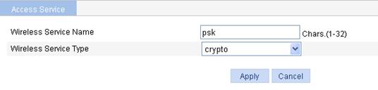
c. On the page that appears, set the service name to psk, select the wireless service type crypto, and click Apply.
Figure 50 Creating a wireless service
3. Configure wireless service.
After you create a wireless service, you will enter the wireless service configuration page.
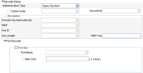
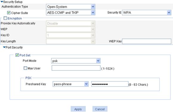
a. In the Security Setup area, select Open-System from the Authentication Type list.
b. Select the Cipher Suite box, select ASE-CCMP and TKIP (select an encryption type as needed), and then select WPA from the Security IE list.
c. Select the Port Set box, and select psk from the Port Mode list.
d. Select pass-phrase from the Pre-shared Key list, and enter the key ID 12345678.
e. Click Apply.
Figure 51 Security setup
4. Enable wireless service.
a. Select Wireless Service > Access Service from the navigation tree.
b. Select the psk[Bind] box.
c. Click Enable.
Figure 52 Enabling wireless service
5. Bind an AP radio to a wireless service
a. Select Wireless Service > Access Service from the navigation tree.
b. Click the ![]() icon corresponding to the wireless service psk.
icon corresponding to the wireless service psk.
c. On the page that appears, select the box before ap with radio mode 802.11n(2.4GHz) and click Bind.
A configuration progress dialog box appears.
d. After the configuration progress is complete, click Close.
Figure 53 Binding an AP radio
6. Enable 802.11n(2.4GHz) radio
a. Select Radio > Radio from the navigation tree.
b. Select the ap box before 802.11n(2.4GHz).
c. Click Enable.
A configuration progress dialog box appears.
d. After the configuration process is complete, click Close.
Figure 54 Enabling 802.11n(2.4GHz) radio
Configuring the client
1. Launch the client, and refresh the network list.
2. Select the configured service in Choose a wireless network (PSK in this example).
3. Click Connect.
4. In the popup dialog box, enter the key (12345678 in this example), and then click Connect.
Figure 55 Configuring the client
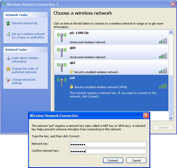
The client has the same pre-shared PSK key as the AP, so the client can associate with the AP.
Figure 56 The client is associated with the AP
Verifying the configuration
· The client can successfully associate with the AP and access the WLAN network.
· You can view the online clients on the page you enter by selecting Summary > Client from the navigation tree.
Local MAC authentication configuration example
Network requirements
AC is connected to AP through a Layer 2 switch, and they are in the same network. Perform MAC authentication on the client.
Figure 57 Network diagram
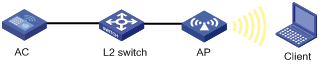
Configuring the AC
1. Create an AP:
a. Select AP > AP Setup from the navigation tree.
b. Click Add.
c. On the page that appears, set the AP name to ap, select the AP model WA2620-AGN, select the serial ID manual, enter the AP serial ID, and click Apply.
Figure 58 Creating an AP
2. Create a wireless service
a. Select Wireless Service > Access Service from the navigation tree.
b. Click Add.
c. On the page that appears, set the service name to mac-auth, select the wireless service type clear, and click Apply.
Figure 59 Creating a wireless service
3. Configure the wireless service:
After you have created a wireless service, you enter the wireless service configuration page.
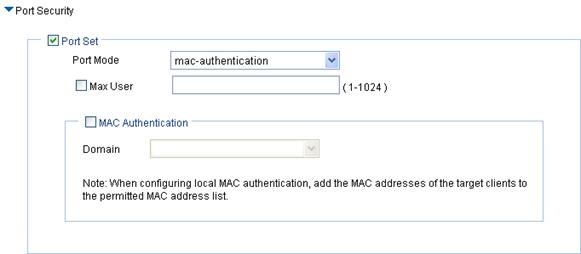
a. In the Security Setup area, select Open-System from the Authentication Type list.
b. Select the Port Set box, and select mac-authentication from the Port Mode list.
c. Select the MAC Authentication box, and select system from the Domain list.
To create a domain, select Authentication > AAA from the navigation tree, click the Domain Setup tab, and enter a domain name in the Domain Name field.
d. Click Apply.
Figure 60 Security setup

4. Enable wireless service.
a. Select Wireless Service > Access Service from the navigation tree.
b. Select the mac-auth box.
c. Click Enable.
Figure 61 Enabling wireless service
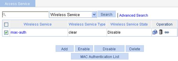
5. Configure a MAC authentication list
a. Select Wireless Service > Access Service from the navigation tree.
b. Click MAC Authentication List.
c. On the page that appears, add a local user in the MAC Address field. 0014-6c8a-43ff is used in this example.
d. Click Add.
Figure 62 Adding a MAC authentication list
6. Bind an AP radio to a wireless service
a. Select Wireless Service > Access Service from the navigation tree.
b. Click the ![]() icon corresponding to the wireless service mac-auth.
icon corresponding to the wireless service mac-auth.
c. On the page that appears, select the box before ap with radio mode 802.11n(2.4GHz) and click Bind.
A configuration progress dialog box appears.
d. After the configuration process is complete, click Close.
Figure 63 Binding an AP radio
7. Enable 802.11n(2.4GHz) radio
a. Select Radio > Radio from the navigation tree.
b. Select the ap 802.11n(2.4GHz) box of the target AP.
c. Click Enable.
A configuration progress dialog box appears.
d. After the configuration process is complete, click Close.
Figure 64 Enabling 802.11n(2.4GHz) radio

Configuring the client
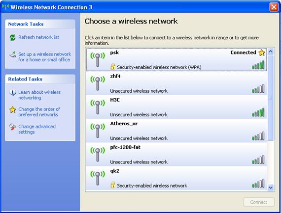
1. Launch the client, and refresh the network list.
2. Select the configured service in Choose a wireless network (mac-auth in this example).
3. Click Connect.
If the MAC address of the client is in the MAC address list, the client can pass the MAC authentication and access the wireless network.
Figure 65 Configuring the client
Verifying the configuration
· The client can successfully associate with the AP and access the WLAN network.
· You can view the online clients on the page you enter by selecting Summary > Client.
Remote MAC authentication configuration example
Network requirements
As shown in Figure 66, perform remote MAC authentication on the client.
· Use the intelligent management center (IMC) as the RADIUS server for authentication, authorization, and accounting (AAA). On the RADIUS server, configure the client's username and password as the MAC address of the client and the shared key as expert. The IP address of the RADIUS server is 10.18.1.88.
· The IP address of the AC is 10.18.1.1. On the AC, configure the shared key for communication with the RADIUS server as expert, and configure the AC to remove the domain name of a username before sending it to the RADIUS server.
Configuring the AC
1. Assign an IP address to the AC:
a. Select Network > VLAN to create a VLAN on the AC.
b. Select Device > Interface Management to assign an IP address to the VLAN interface.
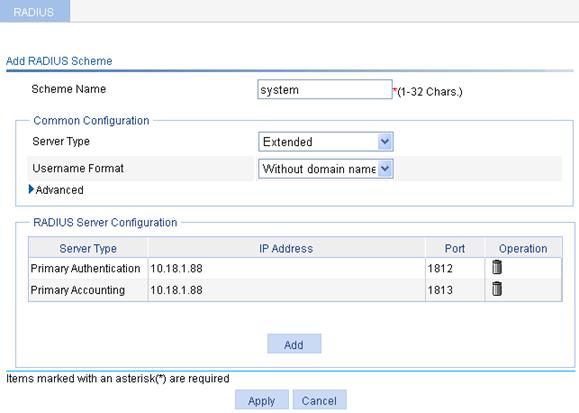
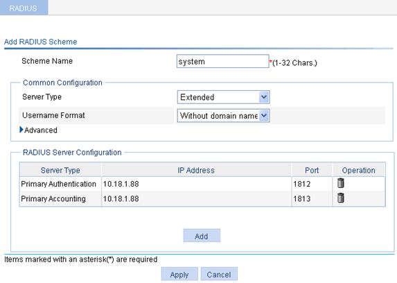
2. Configure a RADIUS scheme:
a. Select Authentication > RADIUS from the navigation tree.
b. Click Add.
c. On the page that appears, add two servers in the RADIUS Server Configuration area, and specify the key expert.
d. Enter mac-auth in the Scheme Name field.
e. Select Extended as the server type.
f. Select Without domain name from the Username Format List.
g. Click Apply.
Figure 67 Configuring RADIUS
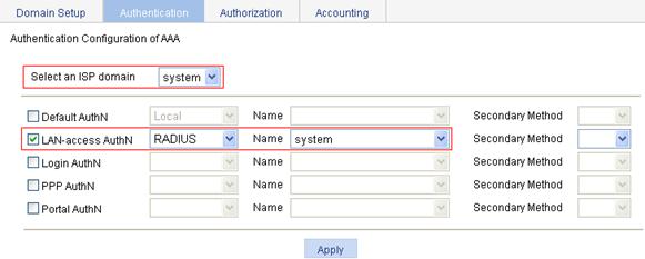
3. Configure AAA:
a. From the navigation tree, select Authentication > AAA.
b. Optional: On the Domain Setup tab, create a new ISP domain.
This example uses the default domain system.
c. On the Authentication tab, select the ISP domain system, select the LAN-access AuthN box, select the authentication mode RADIUS, select the authentication scheme mac-auth from the Name list, and click Apply.
A configuration progress dialog box appears.
d. After the configuration process is complete, click Close.
Figure 68 Configuring the AAA authentication method for the ISP domain
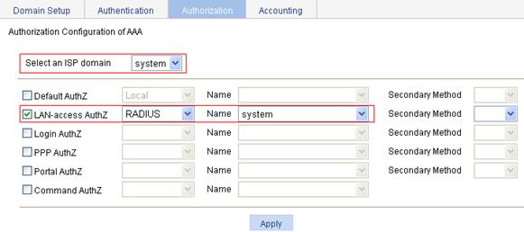
e. On the Authorization tab, select the ISP domain system, select the LAN-access AuthZ box, select the authorization mode RADIUS, select the authorization scheme mac-auth from the Name list, and click Apply.
A configuration progress dialog box appears.
f. After the configuration process is complete, click Close.
Figure 69 Configuring the AAA authorization method for the ISP domain
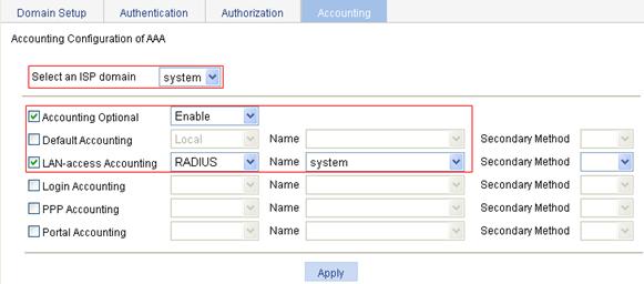
g. On the Accounting tab, select the ISP domain system, select the Accounting Optional box, and select Enable from the Accounting Optional list, select the LAN-access Accounting box, select the accounting method RADIUS, select the accounting scheme mac-auth from the Name list, and click Apply.
A configuration progress dialog box appears.
h. After the configuration process is complete, click Close.
Figure 70 Configuring the AAA accounting method for the ISP domain
4. Create an AP:
a. Select AP > AP Setup from the navigation tree.
b. Click Add.
c. On the page that appears, set the AP name to ap., select the AP model WA2620-AGN., select the serial ID manual, enter the AP serial ID, and click Apply.
Figure 71 AP setup
5. Configure wireless service:
a. Select Wireless Service > Access Service from the navigation tree.
b. Click Add.
c. On the page that appears, set the wireless service name to mac-auth, select the wireless service type clear, and click Apply.
Figure 72 Creating a wireless service
6. Configure MAC authentication:
After you create a wireless service, the wireless service configuration page appears.
a. In the Security Setup area, select Open-System from the Authentication Type list.
b. Select the Port Set box, and select mac-authentication from the Port Mode list.
c. Select the MAC Authentication box, and select system from the Domain list.
d. Click Apply.
A configuration progress dialog box appears.
e. After the configuration process is complete, click Close.
Figure 73 Security setup
7. Enable the wireless service:
a. Select Wireless Service > Access Service from the navigation tree.
b. On the page that appears, select the mac-auth box.
c. Click Enable.
A configuration progress dialog box appears.
d. After the configuration process is complete, click Close.
Figure 74 Enabling the wireless service
8. Bind an AP radio to the wireless service:
a. Select Wireless Service > Access Service from the navigation tree.
b. Click the ![]() icon corresponding to the wireless service mac-auth.
icon corresponding to the wireless service mac-auth.
c. Select the box of the AP with the radio mode 802.11n(2.4GHz).
d. Click Bind.
A configuration progress dialog box appears.
e. After the configuration process is complete, click Close.
Figure 75 Binding an AP radio to a wireless service
9. Enable 802.11n(2.4GHz) radio:
a. Select Radio > Radio from the navigation tree.
b. Select the ap 802.11n(2.4GHz) box of the target AP.
c. Click Enable.
A configuration progress dialog box appears.
d. After the configuration process is complete, click Close.
Figure 76 Enabling 802.11n(2.4GHz) radio
Configuring the RADIUS server (IMCv3)
|
|
NOTE: The following takes the IMC (IMC PLAT 3.20-R2602 and IMC UAM 3.60-E6102) as an example to illustrate the basic configuration of the RADIUS server. |
1. Add an access device.
a. Click the Service tab in the IMC Platform.
b. Select Access Service > Access Device from the navigation tree.
c. Click Add.
d. On the page that appears, add expert for Shared Key, add ports 1812 and 1813 for Authentication Port and Accounting Port respectively, select LAN Access Service for Service Type, select H3C for Access Device Type, select or manually add an access device with the IP address 10.18.1.1, and click Apply.
Figure 77 Adding access device
2. Add service.
a. Click the Service tab.
b. Select Access Service > Access Device from the navigation tree.
c. Click Add.
d. On the page that appears, set the service name to mac, keep the default values for other parameters, and click Apply.
Figure 78 Adding service
3. Add account.
a. Click the User tab.
b. Select User > All Access Users from the navigation tree.
c. Click Add.
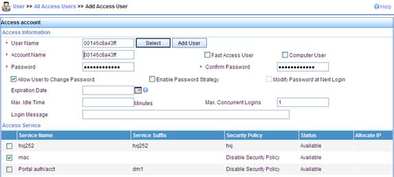
d. On the page that appears, enter a username 00146c8a43ff, add an account and password 00146c8a43ff, select the service mac, and click Apply.
Figure 79 Adding account
Configuring the RADIUS server (IMC v5)
|
|
NOTE: The following takes the IMC (IMC PLAT 5.0 and IMC UAM 5.0) as an example to illustrate the basic configuration of the RADIUS server. |
1. Add an access device.
a. Click the Service tab in the IMC Platform.
b. Select User Access Manager > Access Device Management from the navigation tree.
c. Click Add.
d. On the page that appears, enter 12345678 as the Shared Key, keep the default values for other parameters, select or manually add the access device with the IP address 10.18.1.1, and click Apply.
Figure 80 Adding access device
2. Add service.
a. Click the Service tab.
b. Select User Access Manager > Service Configuration from the navigation tree.
c. Click Add.
d. On the page that appears, set the service name to mac, keep the default values for other parameters, and click Apply.
Figure 81 Adding service
3. Add an account.
a. Click the User tab.
b. Select User > All Access Users from the navigation tree to enter the user page.
c. Click Add.
d. On the page that appears, enter username 00146c8a43ff, set the account name and password both to 00146c8a43ff, select the service mac, and click Apply.
Figure 82 Adding account
Verifying the configuration
· During authentication, the user does not need to enter the username or password. After passing MAC authentication, the client can associate with the AP and access the WLAN.
· You can view the online clients on the page you enter by selecting Summary > Client from the navigation tree.
Remote 802.1X authentication configuration example
Network requirements
Perform remote 802.1X authentication on the client.
· Use the IMC as a RADIUS server for AAA. On the RADIUS server, configure the client's username as user, password as dot1x, and shared key as expert. The IP address of the RADIUS server is 10.18.1.88.
· On the AC, configure the shared key as expert, and configure the AC to remove the domain name of a username before sending it to the RADIUS server. The IP address of the AC is 10.18.1.1.
Figure 83 Network diagram

Configuring the AC
1. Assign an IP address to the AC:
a. Select Network > VLAN to create a VLAN on the AC.
b. Select Device > Interface Management to assign an IP address to the VLAN interface.
a. Select Authentication > RADIUS from the navigation tree.
b. Click Add.
c. On the page that appears, add two servers in the RADIUS Server Configuration, and specify the key expert.
d. Enter 802.1x in the Scheme Name field.
e. Select the server type Extended, and select Without domain name from the Username Format list.
f. Click Apply.
Figure 84 Configuring RADIUS
a. Select Authentication > AAA from the navigation tree.
b. Optional: On the Domain Setup tab, create a new ISP domain.
This example uses the default domain system.
c. On the Authentication tab, select the ISP domain system, select the LAN-access AuthN box, select the authentication mode RADIUS, select the authentication scheme 802.1x from the Name list, and click Apply.
Figure 85 Configuring the AAA authentication method for the ISP domain
d. On the Authorization tab, select the domain name system, select the LAN-access AuthZ box, select the authorization mode RADIUS, select the authorization scheme 802.1x from the Name list, and click Apply.
Figure 86 Configuring the AAA authorization method for the ISP domain
e. On the Accounting tab, select the ISP domain name system, select the Accounting Optional box and then select Enable from the Accounting Optional list, select the LAN-access Accounting box, select the accounting method RADIUS, select the accounting scheme 802.1x from the Name list, and click Apply.
Figure 87 Configuring the AAA accounting method for the ISP domain
4. Create an AP.
a. Select AP > AP Setup from the navigation tree.
b. Click Add.
c. On the page that appears, set the AP name to ap, select the AP model WA2620-AGN, select the serial ID manual, enter the AP serial ID, and click Apply.
Figure 88 AP setup
5. Configure wireless service
a. Select Wireless Service > Access Service from the navigation tree.
b. Click Add.
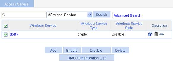
c. On the page that appears, set the service name to dot1x, select the wireless service type crypto, and click Apply.
Figure 89 Creating a wireless service

6. Configure 802.1X authentication.
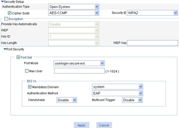
After you create a wireless service, the wireless service configuration page appears.
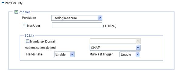
a. In the Security Setup area, select Open-System from the Authentication Type list, select the Cipher Suite box, select AES-CCMP from the Cipher Suite list, and select WPA2 from the Security IE list.
b. Select the Port Set box, and select userlogin-secure-ext from the Port Mode list.
c. Select system from the Mandatory Domain list.
d. Select EAP from the Authentication Method list.
e. Disable Handshake and Multicast Trigger (recommended).
f. Click Apply.
g. A progress dialog box appears. During the process, another dialog box appears asking you whether to enable EAP authentication. Click OK.
h. After the configuration progress is complete, click Close.
Figure 90 Security setup
7. Enable the wireless service
a. Select Wireless Service > Access Service from the navigation tree.
b. On the page that appears, select the dot1x box and click Enable.
Figure 91 Enabling the wireless service
8. Bind an AP radio to the wireless service.
a. Select Wireless Service > Access Service from the navigation tree.
b. Click the ![]() icon corresponding to the wireless service dot1x.
icon corresponding to the wireless service dot1x.
c. Select the box of the AP with the radio mode 802.11n(2.4GHz).
d. Click Bind.
A configuration progress dialog box appears.
e. After the configuration process is complete, click Close.
Figure 92 Binding an AP radio to a wireless service
9. Enable 802.11n(2.4GHz) radio
a. Select Radio > Radio from the navigation tree.
b. Select the box of the target AP.
c. Click Enable.
A configuration progress dialog box appears.
d. After the configuration process is complete, click Close.
Figure 93 Enabling 802.11n(2.4GHz) radio
Configuring the RADIUS server (IMCv3)
|
|
NOTE: The following takes the IMC (IMC PLAT 3.20-R2602 and IMC UAM 3.60-E6102) as an example to illustrate the basic configuration of the RADIUS server. |
1. Add access device.
a. Click the Service tab in the IMC management platform.
b. Select Access Service > Access Device from the navigation tree.
c. Click Add.
d. On the page that appears, enter the shared key expert, enter the authentication and accounting ports 1812 and 1813, select LAN Access Service from the Service Type list, select H3C from the Access Device Type list, select or manually add an access device with the IP address 10.18.1.1, and click Apply.
Figure 94 Adding access device
2. Add service.
a. Click the Service tab.
b. Select Access Service > Access Device from the navigation tree.
c. Click Add.
d. On the page that appears, set the service name to dot1x, and set the Certificate Type to EAP-PEAP AuthN and the Certificate Sub Type to MS-CHAPV2 AuthN, and click Apply.
Figure 95 Adding service
3. Add account.
a. Click the User tab.
b. Select User > All Access Users from the navigation tree.
c. Click Add.
d. On the page that appears, enter a username user, add an account user and password dot1x, and select the service dot1x, and click Apply.
Figure 96 Adding account
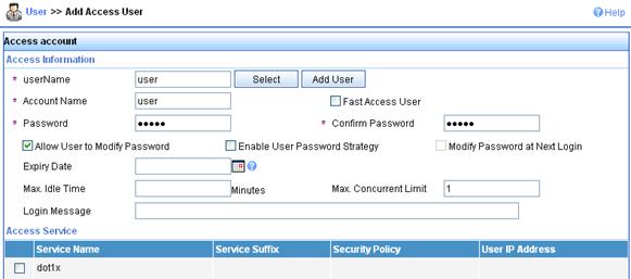
Configuring the RADIUS server (IMC v5)
|
|
NOTE: The following takes the IMC (IMC PLAT 5.0 and IMC UAM 5.0) as an example to illustrate the basic configuration of the RADIUS server. |
1. Add an access device.
a. Click the Service tab in the IMC platform.
b. Select User Access Manager > Access Device Management from the navigation tree.
c. Click Add.
d. On the page that appears, enter 12345678 as the Shared Key, keep the default values for other parameters, and select or manually add the access device with the IP address 10.18.1.1, and click Apply.
Figure 97 Adding access device

2. Add a service.
a. Click the Service tab.
b. Select User Access Manager > Service Configuration from the navigation tree.
c. Click Add.
d. On the page that appears, set the service name to dot1x, and set the Certificate Type to EAP-PEAP AuthN and the Certificate Sub Type to MS-CHAPV2 AuthN, and click Apply.
Figure 98 Adding a service
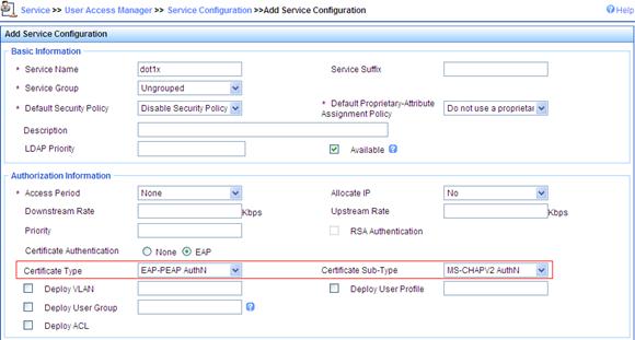
3. Add an account.
a. Click the User tab.
b. Select User > All Access Users from the navigation tree.
c. Click Add.
d. On the page that appears, enter username user, set the account name to user and password to dot1x, and select the service dot1x, and click Apply.
Figure 99 Adding account
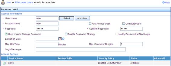
Configuring the wireless client
1.
Double click the ![]() icon at
the bottom right corner of your desktop.
icon at
the bottom right corner of your desktop.
The Wireless Network Connection Status window appears.
2. Click Properties in the General tab.
The Wireless Network Connection Properties window appears.
3. In the Wireless Networks tab, select wireless network with the SSID dot1x, and then click Properties.
The dot1x Properties window appears.
4. In the Authentication tab, select Protected EAP (PEAP) from the EAP type list, and click Properties.
5. In the popup window, clear Validate server certificate, and click Configure.
6. In the popup dialog box, clear Automatically use my Windows logon name and password (and domain if any).
Figure 100 Configuring the wireless client (I)
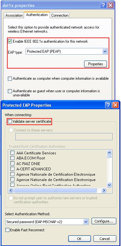
Figure 101 Configuring the wireless client (II)
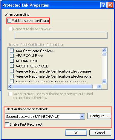
Figure 102 Configuring the wireless client (III)
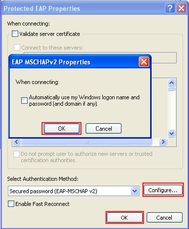
Verifying the configuration
· After the user enters username user and password dot1x in the popup dialog box, the client can associate with the AP and access the WLAN.
· You can view the online clients on the page you enter by selecting Summary > Client.
Dynamic WEP encryption-802.1X authentication configuration example
Network requirements
Perform dynamic WEP encryption-802.1X authentication on the client. More specifically,
· Use the IMC as a RADIUS server for AAA. On the RADIUS server, configure the client's username as user, password as dot1x, and shared key as expert. The IP address of the RADIUS server is 10.18.1.88.
· On the AC, configure the shared key as expert, and configure the AC to remove the domain name of a username before sending it to the RADIUS server. The IP address of the AC is 10.18.1.1.
Figure 103 Network diagram
Configuration procedure
1. Assign an IP address for the AC:
See "Assign an IP address to the AC:."
2. Configure a RADIUS scheme:
See "Configure a RADIUS scheme."
3. Configure AAA:
See "Configure AAA."
4. Configure the AP:
See "Create an AP.."
5. Create a wireless service:
a. Select Wireless Service > Access Service from the navigation tree.
b. Click Add.
c. On the page that appears, set the service name to dot1x, select the wireless service type crypto, and click Apply.
Figure 104 Creating a wireless service
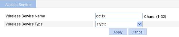
6. Configure 802.1X authentication.
After you create a wireless service, the wireless service configuration page appears.
a. In the Security Setup area, select Open-System from the Authentication Type list.
b. Select Encryption, and select Enable from the Provide Key Automatically list.
c. Select the Cipher Suite box, select CCMP from the Cipher Suite list, and select WPA2 from the Security IE list.
d. Select the Port Set box, and select userlogin-secure-ext from the Port Mode list.
e. Select system from the Mandatory Domain list.
f. Select EAP from the Authentication Method list.
g. Disable Handshake and Multicast Trigger (recommended).
h. Click Apply.
Figure 105 Security setup
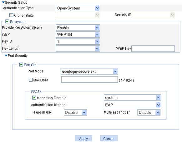
7. Enable the wireless service.
a. Select Wireless Service > Access Service from the navigation tree.
b. On the page that appears, select the dot1x box and click Enable.
Figure 106 Enabling the wireless service
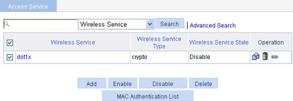
8. Bind an AP radio to the wireless service.
a. Select Wireless Service > Access Service from the navigation tree.
b. Click the ![]() icon corresponding to the wireless service dot1x.
icon corresponding to the wireless service dot1x.
c. On the page that appears, select the box of the AP with the radio mode 802.11n(2.4GHz) and click Bind.
Figure 107 Binding an AP radio to a wireless service
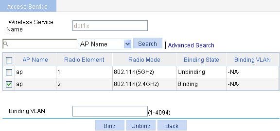
9. Enable 802.11n(2.4GHz) radio:
See "Enable 802.11n(2.4GHz) radio."
10. Configure the RADIUS server (IMCv3):
See "Configuring the RADIUS server (IMCv3)."
11. Configure the RADIUS server (IMCv5):
See "Configuring the RADIUS server (IMC v5)."
Configuring the wireless client
1.
Double click the ![]() icon at
the bottom right corner of your desktop.
icon at
the bottom right corner of your desktop.
2. The Wireless Network Connection Status window appears.
3. Click Properties.
The Wireless Network window appears.
4. Click Add.
5. Click the Association tab, and enter dot1x in the Network name (SSID) field. Make sure that you have selected The key is provided for me automatically.
Figure 108 Configuring the wireless client (I)
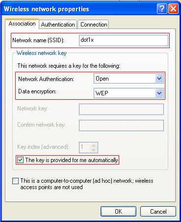
6. On the Authentication tab, select Protected EAP (PEAP) from the EAP type list, and click Properties.
7. In the popup window, clear Validate server certificate, and click Configure.
8. In the popup dialog box, clear Automatically use my Windows logon name and password (and domain if any), and then click OK.
Figure 109 Configuring the wireless client (II)
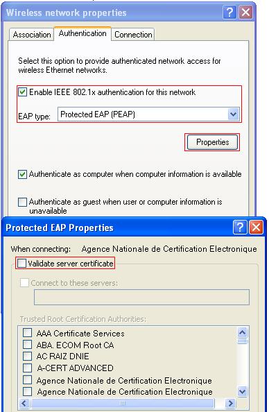
Figure 110 Configuring the wireless client (III)
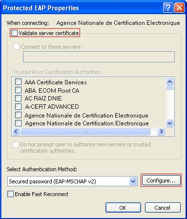
Verifying the configuration
· After the user enters username user and password dot1x in the popup dialog box, the client can associate with the AP and access the WLAN.
· You can view the online clients on the page you enter by selecting Summary > Client.
Different from a traditional WLAN, a WLAN mesh network allows for wireless connections between APs, making the WLAN more mobile and flexible. Moreover, multi-hop wireless links can be established between APs. From the perspective of end users, a WLAN mesh network has no difference from a traditional WLAN.
Mesh overview
Basic concepts in WLAN mesh
Figure 111 Typical WLAN mesh network
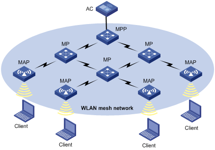
As shown in Figure 111, the concepts involved in WLAN mesh are described below.
|
Concept |
Description |
|
Access controller (AC) |
A device that controls and manages all the APs in the WLAN. |
|
Mesh point (MP) |
A wireless AP that connects to a mesh portal point (MPP) through a wireless connection but cannot have any client attached. |
|
Mesh access point (MAP) |
An AP providing the mesh service and the access service concurrently. |
|
Mesh portal point (MPP) |
A wireless AP that connects to an AC through a wired connection. |
|
Mesh link |
A wireless link between MPs. |
Advantages of WLAN mesh
The WLAN mesh technology allows operators to easily deploy wireless networks anywhere and anytime. WLAN mesh has the following advantages:
· High performance/price ratio—In a mesh network, only the MPPs need to connect to a wired network. In this way, the dependency on the wired network is reduced to the minimum extent, and the investment in wired devices, cabling, and installation is greatly reduced.
· Excellent scalability—In a mesh network, the APs can automatically discover each other and initiate wireless link setup. To add new APs to the mesh network, you just need to install these new APs and perform the related configurations on them.
· Fast deployment—Since only the MPPs need to connect to a wired network, WLAN mesh greatly reduces the network deployment time.
· Various application scenarios—The mesh network is applicable to enterprise, office, and campus networks, which are common application scenarios of traditional WLANs, and also applicable to large-sized warehouse, port, MAN, railway transportation, and crisis communication networks.
· High reliability—In a traditional WLAN, when the wired upstream link of an AP fails, all clients associated with the AP cannot access the WLAN. Comparatively, in a mesh network, all APs are fully meshed. There are multiple available wireless links for a mesh AP to reach a portal node in the wired network, thus avoiding single point failure effectively.
Deployment scenarios
This section covers deployment scenarios of WLAN mesh, which are in two categories: subway networking and normal networking.
Normal WLAN mesh deployment
1. Normal fit MP scenario
As shown in Figure 112, two mesh networks are controlled by the same AC. At least one MPP in a mesh has wired connectivity with the AC. When an MP comes up, it scans the network and forms temporary connections with all available MPs in its vicinity. Such temporary connections allow the MP to connect to the AC for downloading its configurations. After downloading its configurations from the AC, the MP will establish secure connections with neighbors sharing the same pre-shared key.
Figure 112 Normal fit MP scenario
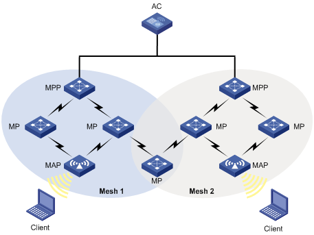
2. One fit MP with two radios, each on a different mesh
As shown in Figure 113, to avoid cross-interruption between Mesh 1 and Mesh 2, you can configure two radios for an MP, each of which is present in a different mesh network. The only constraint is that both meshes have to be managed by the same AC.
Figure 113 Two radios on different meshes
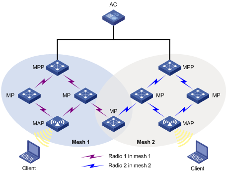
3. One fit MP with two radios on the same mesh
As shown in Figure 114, Radio 1 of MP 1 joins the mesh through the MPP. In this case, only Radio 1 can provide access for downstream MPs. Radio 2 cannot automatically access the mesh and provide the mesh service.
Figure 114 Two radios on different meshes
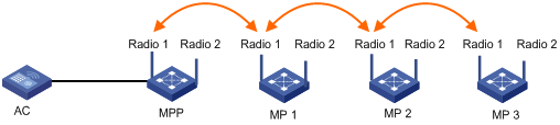
If an MP supports three radios, you can configure Radio 1 as the uplink interface, Radio 2 as the downlink interface, and Radio 3 as the multi-beam antenna. To utilize the dual-radio resources on MPs, you can establish the network as shown in Figure 115. In such a network, when Radio 1 of MP 1 accesses the mesh, Radio 2 on MP 1 also automatically joins the mesh. In this network, you should apply the same mesh service to both Radio 1 and Radio 2. For more information, see "Tri-radio mesh configuration example."
Figure 115 Two radios on the same mesh
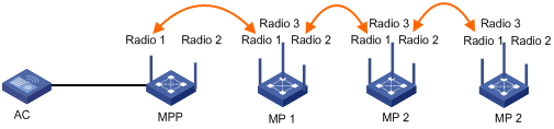
Subway WLAN mesh deployment
A subway is an important traffic means for a modern city. In a subway system, control information must be sent to trains to effectively manage trains and provide various services to customers.
As shown in Figure 116, a subway WLAN mesh solution has fit MPs deployed along the rail, which are managed by the same AC. A train MP (fat AP) continuously scans new rail MPs (fit APs), and sets up active/dormant links with the rail MPs with the best signal quality. The active mesh link is used for data transmission, and the dormant mesh link acts as the backup link.
Figure 116 Subway deployment of mesh
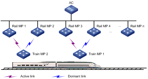
The subway WLAN mesh deployment is based on the Mobile Link Switch Protocol (MLSP), which is used for high-speed link switch with zero packet loss during train movement. New IEEE standard 802.11s is adopted as the underlying protocol for link formation and communication between mobile radio (MR) and wayside AP. Train MPs are not required to act as authenticators.
WLAN mesh security
A WLAN network uses air as the communication medium, so it is vulnerable to malicious attacks. In a mesh network, a wireless connection passes through multiple hops, and thus a mesh network is more vulnerable to malicious attacks. Therefore, WLAN mesh network security becomes an essential part of WLAN mesh networks. Security involves encryption algorithms and distribution and management of keys. Currently, PSK + CCMP combination is used for securing mesh networks.
Mobile link switch protocol
At any given time, an active link should be available between a rail MP and a train MP for data communication. MLSP was developed to create and break links during train movement.
As shown in Figure 117, when the train is moving, it must break the existing active link with rail MP 2 and create a new active link with another rail MP.

· Active Link: Logical link through which all data communication from/to a train MP happens.
· Dormant Link: Logical link over which no data transfer happens, but it satisfies all the criteria for becoming an active link.
MLSP advantages
· MLSP ensures that the link switch time is less than 30 ms.
· MLSP works well even if the devices get saturated at high power level.
· MLSP achieves zero packet loss during link switch.
Operation of MLSP
MLSP establishes multiple links at any given time between a train MP and multiple rail MPs to provide link redundancy, thus ensuring high performance and good robustness for the network.
The following parameters are considered by MLSP for link switch. Based on the deployment, all these parameters are tunable to achieve best results.
· Link formation RSSI/link hold RSSI—This is the minimum RSSI to allow a link to be formed and held. Therefore, the minimum RSSI must be ensured at any given point in the tunnel. Otherwise, the error rate can be very high.
· Link switch margin—If the RSSI of the new link is greater than that of the current active link by the link switch margin, active link switch occurs. This mechanism is used to avoid frequent link switch.
· Link hold time—An active link remains up within the link hold time, even if the link switch margin is reached. This mechanism is used to avoid frequent link switch.
· Link saturation RSSI—This is the upper limit of RSSI on the active link. If the value is reached, link switch occurs.
Formation of dormant links
A train MP performs active scanning to find neighboring rail MPs by sending probe requests at a very high rate. Based on probe responses received, the train MP forms a neighbor table.
After that, the train MP creates dormant links with rail MPs that have an RSSI value greater than the link formation RSSI.
Selection of active link
A train MP selects the active link from dormant links based on the following rules:
1. If no dormant link is available, the active link cannot be formed.
2. Active link switch will not happen within the link hold time, except the following two conditions:
¡ Condition 1—The active link RSSI exceeds the link saturation RSSI.
¡ Condition 2—The active link RSSI is below the link hold RSSI.
3. When the link hold timer expires, if no dormant link has RSSI greater than the active link RSSI by the link switch margin, link switch will not happen.
4. In normal scenarios, active link switch will happen when all of these following conditions are met:
¡ The link hold timer expires.
¡ The dormant link's RSSI is higher than the current active link's RSSI by the link switch margin.
¡ The dormant link RSSI is not greater than the link saturation RSSI.
5. Once the RSSI of the active and dormant links has gone below the link hold RSSI, links should be broken. However, to ensure service availability in worse cases, if the active link RSSI has gone below the link hold RSSI and no dormant links exist, the active link is not broken.
Mesh network topologies
The mesh feature supports the following three topologies. Mesh is implemented through configuration of a peer MAC address for each AP. For more information, see "Configuring a peer MAC address."
Point to point connection
In this topology, by configuring the peer MAC address for an AP, you can determine the mesh link to be formed.
Figure 118 Mesh point to point topology
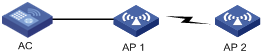
Point to multi-point connection
In this topology, a centralized bridging device forms wireless links with multiple MPs to bridge data among multiple LAN segments. As shown below, data transferred between different LAN segments goes via AP 1.
Figure 119 Mesh point to multi-point topology
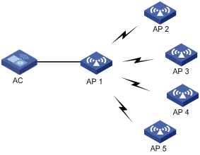
Self topology detection and bridging connection
In this topology, MPs automatically detect neighbors and form wireless links to provide wireless connectivity between LAN segments, as shown Figure 120. Loops are easy to occur in the topology. In the topology, you can use mesh routes to selectively block redundant links to eliminate loops, and back up the links when the mesh links fail.
Figure 120 Self topology detection and bridging
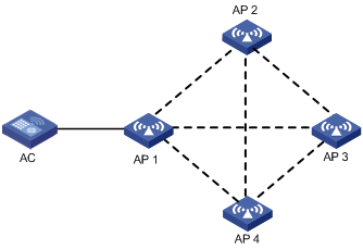
Configuring mesh service
Configuring mesh service
Creating a mesh service
1. Select Wireless Service > Mesh Service from the navigation tree.
2. Click the Mesh Service tab.
Figure 121 Mesh service configuration page
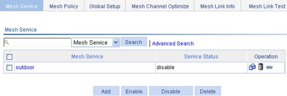
3. Click Add.
Figure 122 Creating a mesh service

4. Configure the mesh service as described in Table 15.
5. Click Apply.
|
Item |
Description |
|
Mesh Service Name |
Name of the created mesh service. |
Configuring a mesh service
1. Select Wireless Service > Mesh Service from the navigation tree.
2. Click the Mesh Service tab.
3.
Click the ![]() icon corresponding to the target mesh service to enter the page for configuring mesh
service.
icon corresponding to the target mesh service to enter the page for configuring mesh
service.
Figure 123 Configuring mesh service
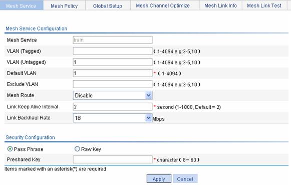
4. Configure the mesh service as described in Table 16.
5. Click Apply.
|
Item |
Description |
|
Mesh Service |
Display the selected mesh service name. |
|
VLAN (Tagged) |
Enter the ID of the VLAN whose packets are to be sent tagged. VLAN (Tagged) indicates that the port sends the traffic of the VLAN without removing the VLAN tag. |
|
VLAN (Untagged) |
Enter the ID of the VLAN whose packets are to be sent untagged. VLAN (Untagged) indicates that the ports send the traffic of the VLAN with the VLAN tag removed. |
|
Default VLAN |
Set the default VLAN. By default, the default VLAN of all ports is VLAN 1. After you set the new default VLAN, VLAN 1 is the ID of the VLAN whose packets are to be sent untagged. |
|
Exclude VLAN |
Remove the IDs of the VLANs whose packets are to be sent untagged and tagged. |
|
Mesh Route |
Enable or disable mesh route selection algorithm: · Disable—Disable the mesh route selection algorithm. · Enable—Enable the mesh route selection algorithm. By default, the mesh route selection algorithm is disabled. |
|
Link Keep Alive Interval |
Configure the mesh link keep-alive interval. |
|
Link Backhaul Rate |
Configure the backhaul radio rate. |
|
Security Configuration |
|
|
Pass Phrase |
Enter a pre-shared key in the format of character string. |
|
Raw Key |
Enter a pre-shared key in the format of hexadecimal digits. |
|
Pre-shared Key |
Pre-shared key. · A string of 8 to 63 characters, or. · A valid hexadecimal number of 64 bits. |
Binding an AP radio to a mesh service
1. Select Wireless Service > Mesh Service from the navigation tree.
2.
Click the ![]() icon to
enter the page for binding an AP radio to a mesh service.
icon to
enter the page for binding an AP radio to a mesh service.
3. Select the AP radio to be bound.
4. Click Bind.
Figure 124 Binding an AP radio to a mesh service
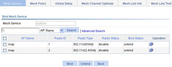
Enabling a mesh service
1. Select Wireless Service > Mesh Service from the navigation tree.
2. Click the Mesh Service tab to enter the mesh service configuration page.
Figure 125 Enabling a mesh service
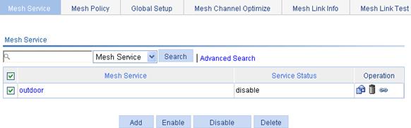
3. Select the mesh service to be enabled.
4. Click Enable.
Displaying the detailed information of a mesh service
1. Select Wireless Service > Mesh Service from the navigation tree.
2. Click the Mesh Service tab to enter the mesh service configuration page.
3. Click a mesh service to see its detailed information.
Figure 126 Mesh service detailed information
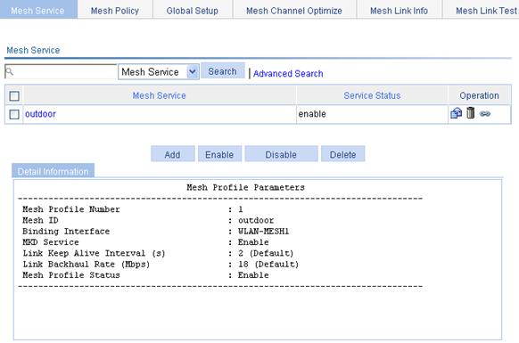
Table 17 Field description
|
Field |
Description |
|
Mesh Profile Number |
Mesh service number. |
|
Mesh ID |
Mesh ID of the mesh service. |
|
Binding Interface |
Mesh interface bound to the mesh service. |
|
MKD Service |
MKD service status, which can be: · Enable—Indicates that the MKD service is enabled. · Disable—Indicates that the MKD service is disabled. |
|
Link Keep Alive Interval |
Interval to send keep-alive packets. |
|
Link Backhaul Rate |
Link backhaul rate. |
|
Mesh Profile Status |
Mesh service status, which can be: · Enable—Indicates that the mesh service is enabled. · Disable—Indicates that the mesh service is disabled. |
Configuring a mesh policy
Creating a mesh policy
1. Select Wireless Service > Mesh Service from the navigation tree.
2. Click the Mesh Service tab to enter the mesh policy configuration page.
Figure 127 Mesh policy configuration page

3. Click Add.
Figure 128 Create a mesh policy
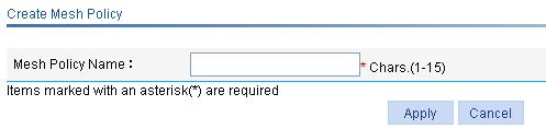
4. Configure the mesh policy as described in Table 18.
5. Click Apply.
|
Item |
Description |
|
Mesh Policy Name |
Name of the created mesh policy. The created mesh policies use the contents of the default mesh policy default_mp_plcy. |
Configuring a mesh policy
1. Select Wireless Service > Mesh Service from the navigation tree.
2. Click the Mesh Policy tab.
3.
Click the ![]() icon corresponding to the target mesh policy to enter the mesh policy configuration page.
icon corresponding to the target mesh policy to enter the mesh policy configuration page.
Figure 129 Configuring a mesh policy
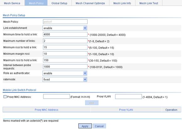
4. Configure the mesh policy as described in Table 19.
5. Click Apply.
|
Item |
Description |
|
Mesh Policy |
Display the name of the created mesh policy. |
|
Link establishment |
By default, link initiation is enabled.
· This feature should be disabled when you configure an MP policy for a rail AP. · This feature is used on train MPs in subway WLAN mesh deployment. |
|
Minimum time to hold a link |
Set the link hold time. An active link remains up within the link hold time, even if the link switch margin is reached. This mechanism is used to avoid frequent link switch. |
|
Maximum number of links |
Set the maximum number of links that an MP can form in a mesh network.
When configuring mesh, if the number of mesh links configured on an AP is greater than 2, you need to configure the maximum links that an MP can form as needed. |
|
Minimum rssi to hold a link |
Set link formation/link hold RSSI (received signal strength indicator). This is the minimum RSSI to allow a link to be formed and held. Therefore, the minimum RSSI must be ensured at any given point in the tunnel. Otherwise, the error rate can be very high. |
|
Minimum margin rssi |
Set the link switch margin. If the RSSI of the new link is greater than that of the current active link by the link switch margin, active link switch will happen. This mechanism is used to avoid frequent link switch. |
|
Maximum rssi to hold a link |
Set link saturation RSSI. This is the upper limit of RSSI on the active link. If the value is reached, the chipset is saturated and link switch will happen. |
|
Interval between probe requests |
Set the probe request interval. |
|
Role as authenticator |
By default, whether a device plays the role of an authenticator is based on negotiation results. |
|
ratemode |
· fixed—The rate adopted is of a fixed value. It is the maximum rate of the current radio. · realtime—The rate adopted changes with the link quality, that is, the rate changes with the change of the RSSI of the current radio. The fixed mode is adopted by default.. |
|
The Mobile Link Switch Protocol (MLSP) implements high-speed link switch with zero packet loss during train movement. It is applicable to subway WLAN mesh deployment only. |
|
|
Proxy MAC Address |
Select the Proxy MAC Address option to specify the MAC address of the peer device. |
|
Proxy VLAN |
VLAN ID of the peer device. |
Binding an AP radio to a mesh policy
1. Select Wireless Service > Mesh Service from the navigation tree.
2. Click the Mesh Policy tab.
3.
Click the ![]() button corresponding to the target mesh policy.
button corresponding to the target mesh policy.
4. Select the AP radio to be bound.
5. Click Bind.
Displaying the detailed information of a mesh policy
1. Select Wireless Service > Mesh Service from the navigation tree.
2. Click the Mesh Policy tab to enter the mesh policy configuration page.
3. Click a mesh policy to see its detailed information.
Figure 130 Mesh policy detailed information
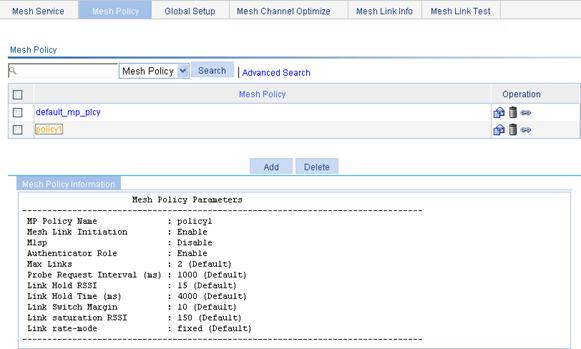
Table 20 Field description
|
Field |
Description |
|
MP Policy Name |
Name of the mesh policy. |
|
Mesh Link Initiation |
Whether link initiation is enabled or not. |
|
Mlsp |
Mobile Link Switch Protocol (MLSP) status, which can be: · Enable—Indicates that MLSP is enabled. · Disable—Indicates that MLSP is disabled. |
|
Authenticator Role |
Authenticator role status, which can be: · Enable—Indicates that the authenticator role is enabled. · Disable—Indicates that the authenticator role is disabled. |
|
Max Links |
Maximum number of links on a device using this mesh policy. |
|
Probe Request Interval (ms) |
Interval between probe requests sent by a device using this mesh policy. |
|
Link Hold RSSI |
Link hold RSSI. |
|
Link Hold Time (ms) |
Link hold time. |
|
Link Switch Margin |
Link switch margin. |
|
Link saturation RSSI |
Link saturation RSSI. |
|
Link rate-mode |
Method of calculating the link cost, which can be: · Fixed—Indicates that the mesh interface rate is fixed. · real-time—Indicates that the mesh interface rate changes with the RSSI in real-time. |
Mesh global setup
Mesh basic setup
1. Select Wireless Service > Mesh Service from the navigation tree.
2. Click the Global Setup tab to enter the mesh global setup page.
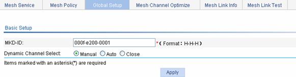
3. Configure the basic mesh settings as described in Table 21.
4. Click Apply.
|
Item |
Description |
|
MKD-ID |
· Make sure the MAC address configured is unused and has the correct vendor specific part. · The MAC address of an AC should not be configured as the MKD ID. |
|
Dynamic Channel Select |
· Manual—Select one-time dynamic channel selection (DFS) and click Apply to enable it. After manual mode is selected, if no mesh network is manually specified when the next calibration interval is reached, the AC will refresh radio information of all mesh networks that it manages, and display it on the Radio Info tab of the Mesh Channel Optimize page. You can view the radio information and select mesh networks for which one-time DFS will be performed on the Mesh Channel Optimize tab. After that, if you want the AC to perform DFS for the mesh network, you have to make this configuration again. · Auto—Select auto-DFS and click Apply to enable it. Auto-DFS applies to all mesh networks where the working channels of the radios are automatically selected. With auto DFS enabled, an AC makes DFS decisions at the calibrate interval automatically. · Close—Close DFS. At the next calibration interval, the radio information and channel switching information on the Mesh Channel Optimize page will be cleared. By default, DFS for a mesh network is disabled.
Before enabling auto or one-time DFS for a mesh network, make sure that auto mode is selected for the working channel of radios in the mesh network. For the related configuration, see "Radio configuration." |
Enabling mesh portal service
1. Select Wireless Service > Mesh Service from the navigation tree.
2. Click the Global Setup tab to enter the mesh portal service configuration page.
Figure 132 Mesh portal service configuration page
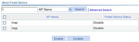
3. Select the AP for which mesh portal service is to be enabled.
4. Click Enable.
Configuring a working channel
You can configure a working channel in one of the following ways:
Manual
1. Select Radio > Radio from the navigation tree.
Figure 133 Radio configuration page

2. On the page that appears, select a specified channel from the Channel list.
3. Click Apply.
|
|
NOTE: Specify a working channel for the radios of the MAP and MPP, and the working channel on the radio of the MAP should be consistent with that on the MPP. |
Auto
Set the working channel mode on the MPP and MAP to auto so that the working channel is automatically negotiated when a WDS link is established between the MPP and MAP.
|
|
NOTE: If you configure the working channel mode of the radios of the MPP and MAP as auto, the automatically selected working channel is a non-radar channel. |
Enabling radio
1. Select Radio > Radio from the navigation tree to enter the radio setup page.
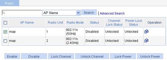
2. Select the radio mode to be enabled.
3. Click Enable.
Configuring a peer MAC address
1. Select Wireless Service > Mesh Service from the navigation tree.
2.
Click ![]() to enter the page for binding an AP radio to a mesh service.
to enter the page for binding an AP radio to a mesh service.
3.
Select the AP radio to be bound, and click the ![]() icon to enter the page for configuring a peer MAC address.
icon to enter the page for configuring a peer MAC address.
Figure 135 Configuring a peer MAC address
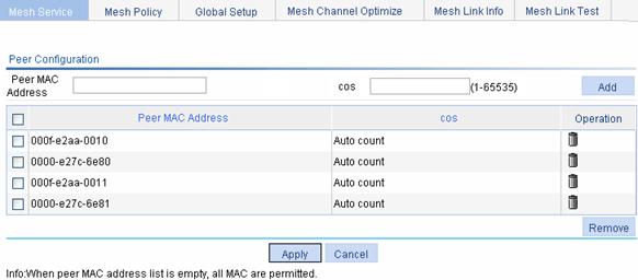
4. Configure the peer MAC address as described in Table 22.
5. Click Apply.
|
Item |
Description |
|
Peer MAC Address |
The mesh feature supports three topologies. For more information, see "Mesh network topologies." The mesh feature is implemented through configuration of peer MAC addresses for each AP. |
|
cos |
Sets the STP cost of the mesh link to the peer. If not configured, the STP cost is automatically calculated by STP. You can view the cost of the mesh link on the page shown in Figure 135. |
Mesh DFS
Displaying radio information
1. Select Wireless Service > Mesh Service from the navigation tree.
2. Click the Mesh Channel Optimize tab to enter the mesh optimization tab.
3. Click the specified mesh network, and click the Radio Info tab to enter the page shown in Figure 136 to view radio information.
Figure 136 Displaying radio information
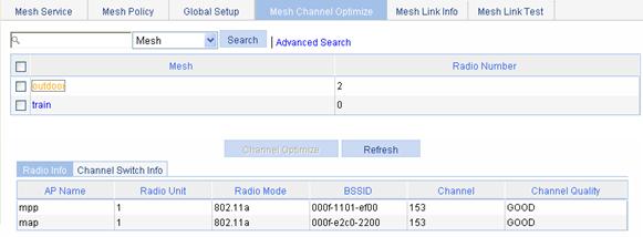
Displaying channel switch information
1. Select Wireless Service > Mesh Service from the navigation tree.
2. Click the Mesh Channel Optimize tab to enter the mesh optimization tab.
3. Click the mesh network, and then select the Channel Switch Info tab to enter the page shown in Figure 137 to view the channel switching information.
Figure 137 Mesh channel switching information

|
|
NOTE: · If you select Auto or Close for dynamic channel selection on the Global Setup tab, when you enter the Mesh Channel Optimize page, the Channel Optimize button is grayed out, meaning you cannot perform the operation. · If you select manual DFS on the Global Setup tab, select mesh networks where DFS will be performed, and then click Channel Optimize to complete DFS. In auto mode, DFS is performed at the calibration interval; in manual mode, DFS is performed for once. |
Table 23 Field description
|
Field |
Description |
|
AP |
AP name in the mesh network. |
|
Radio |
Radio of the AP. |
|
Chl(After/Before) |
Channels before and after channel optimization. |
|
Date(yyyy-mm-dd) |
Date, in the format of yyyy-mm-dd. |
|
Time(hh:mm:ss) |
Time, in the format of hh:mm:ss. |
Displaying the mesh link status
Mesh link monitoring
1. Select Wireless Service > Mesh Service from the navigation tree.
2. Click the Mesh Link Info tab to enter the mesh link monitoring page.
Figure 138 Displaying the mesh link monitoring information
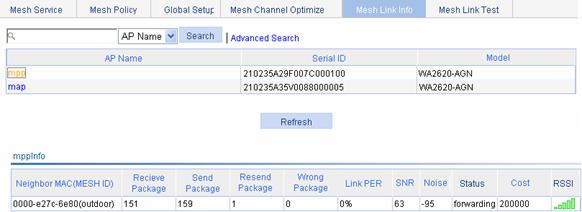
You can monitor the mesh link status in real-time on the mesh link monitoring page.
Mesh link test
1. Select Wireless Service > Mesh Service from the navigation tree.
2. Click the Mesh Link Test tab to enter the mesh link test page.
Figure 139 Displaying mesh link test information
3. Select the box of the target AP.
4. Click Begin.
Normal WLAN mesh configuration example
Network requirements
As shown in the figure below, establish a mesh link between the MAP and the MPP.
Configure 802.11g on the MAP so that the client can access the network.
1. Establish a mesh link between the MPP and the MAP by following these steps:
¡ Configure MAP and MPP—Select AP > AP Setup from the navigation tree, and click Add to configure MAP and MPP. For more information, see "Create an MAP and MPP."
¡ Configure mesh service—After creating a mesh service and configuring a pre-shared key, you can bind the mesh service to the AP and enable the mesh service. For more information, see "Create a mesh service:."
¡ Configure a mesh policy—A mesh policy exists by default. You can create a mesh policy and bind the mesh policy to an AP. For more information, see "(Optional) Configure a mesh policy."
¡ Mesh global setup—Configure an MKD-ID (which exists by default), enable mesh portal service for the MPP. For more information, see "Configure mesh service globally."
¡ Configure the same working channel, and enable the radio. For more information, see "Configure the same working channel and enable the radio on the MAP and MPP:."
2. Configure 802.11g service on the MAP to enable the client to access the WLAN network.
For more information, see "Wireless service configuration example."
Figure 140 Network diagram
Configuring the AC
a. Select AP> AP Setup from the navigation tree.
b. Click Add.
c. On the page that appears, set the AP name to map, select the AP model WA2620-AGN, select the serial ID manual, enter the AP serial ID, and click Apply.
Figure 141 AP setup
d. Configure MPP by following the same steps.
a. Select Wireless Service > Mesh Service from the navigation tree.
b. Click the Mesh Service tab.
c. Click Add.
d. On the page that appears, set the mesh service name to outdoor and click Apply.
After completing mesh service configuration, you enter the page shown in Figure 143.
Figure 142 Creating a mesh service
Figure 143 Configuring a pre-shared key
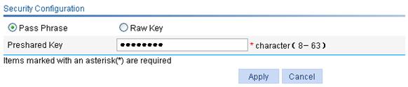
e. Select Pass Phrase, and set the pre-shared key to 12345678.
f. Click Apply.
3. Bind an AP radio to the mesh service.
a. Select Wireless Service > Mesh Service from the navigation tree.
b. Click the ![]() icon corresponding to the mesh service outdoor to enter the page for binding an AP radio to a mesh service.
icon corresponding to the mesh service outdoor to enter the page for binding an AP radio to a mesh service.
c. Select the AP radios to be bound.
d. Click Bind.
Figure 144 Binding an AP radio to a mesh service
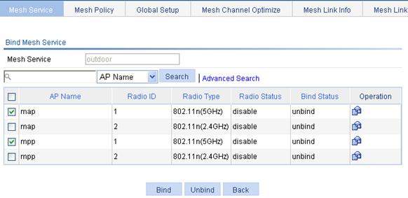
4. Enable the mesh service.
a. Select Wireless Service > Mesh Service from the navigation tree.
Figure 145 Enabling the mesh service
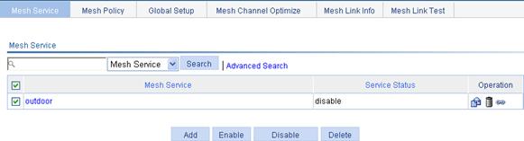
b. Select the mesh service to be enabled.
c. Click Enable.
5. (Optional) Configure a mesh policy (by default, the default mesh policy default_mp_plcy already exists.)
|
|
NOTE: A mesh policy exists by default. You can create a mesh policy and bind the mesh policy to an AP as needed. By default, the default_mp_plcy mesh policy is mapped to an AP. |
6. Configure mesh service globally:
a. (Optional) Select Wireless Service > Mesh Service from the navigation tree, and click the Global Setup tab to enter the mesh global setup page to set the MKD-ID (By default, the MKD-ID exists.)
b. Select the MPP that has wired connectivity with the AC to enable mesh portal service.
c. Click Enable.
Figure 146 Mesh portal service configuration page
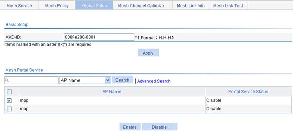
7. Configure the same working channel and enable the radio on the MAP and MPP:
a. Select Radio > Radio from the navigation tree.
b. Click the ![]() icon corresponding to the target MAP to enter the radio setup page.
icon corresponding to the target MAP to enter the radio setup page.
Figure 147 Configuring the working channel
c. Select the channel to be used from the Channel list.
d. Click Apply.
You can follow this step to configure the working channel for the MPP. Note that the working channel of the radio on the MPP must be the same as that on the MAP.
8. Enable radio:
a. Select Radio > Radio from the navigation tree.
b. Select the radio modes to be enabled for the MAP and MPP.
c. Click Enable.
Figure 148 Enabling radio
Verifying the configuration
· The mesh link between the MAP and the MPP has been established, and they can ping each other.
· After 802.11n(2.4GHz) is configured on the MAP, the client can access the network through the mesh link.
Subway WLAN mesh configuration example
Network requirements
· As shown in Figure 149, all rail MPs are connected to an AC.
· Configure WLAN mesh so that the train MP will form links with rail MPs during movement, among them one link is the active link and all others are dormant links.
Subway WLAN mesh configuration is basically the same as normal WLAN mesh configuration. Note the following guidelines when you configure subway WLAN mesh:
1. Create a rail AP mesh policy:
¡ Disable the link initiation function. For more information, see "Configuring a mesh policy."
¡ Enable mesh portal service. For more information, see "Enabling mesh portal service."
2. Create a train AP mesh policy:
¡ Enable MLSP.
¡ Configure MLSP proxy MAC address and VLAN information.
¡ Disable Role as authenticator. For more information, see "Configuring a mesh policy."
¡ Set the value of maximum links that an MP can form in a mesh network (the default value is 2.). For more information, see "Configuring a mesh policy."
Configuring the AC
Subway mesh configuration differs from normal WLAN mesh configuration in the mesh policy configuration of rail APs and train APs. Other configurations are the same. For more information, see "Configuring the AC."
Mesh point-to-multipoint configuration example
Network requirements
AP 1 operates as an MPP to establish a mesh link with AP 2, AP 3, AP 4, and AP 5 respectively.
The mesh configuration is the same as the normal WLAN mesh configuration.
Figure 150 Network diagram

Configuration considerations
· Configure a peer MAC address for each radio interface. Configure the MAC addresses of AP 2 through AP 5 on AP 1, and configure the MAC address of AP 1 on AP 2 through AP 5.
· Set the value of maximum links that an MP can form in a mesh network (The default value is 2. It should be set to 4 in this example.). For more information, see "Configuring a mesh policy."
Configuring the AC
Mesh configuration is the same as normal WLAN mesh configuration. For more information, see "Configuring the AC."
Tri-radio mesh configuration example
Network requirements
As shown in Figure 151, set up mesh links between MPs and the MPP, and use radio resources to make Radio 1 of MPP, Radio 1 and Radio 2 of MP, and Radio 1 of an MP 2 join the same mesh and use Radio 3 as the multi-beam antenna, which provides the wireless access service.
Configuration considerations
1. Configure the mesh service:
The mesh configuration here is similar to a common wireless mesh configuration. Pay attention to the following points:
¡ Radios joining the same mesh must use the same mesh service. Thus, bind Radio 1 of MPP, Radio 1 and Radio 2 of MP 1, and Radio 1 of MP 2 to the same mesh service.
Figure 152 Binding radios to the mesh service

¡ On Radio 1 of the MPP, configure Radio 1 of MP 1 as the peer MAC address. Similarly, configure Radio 1 of the MPP as the peer MAC address on MP 1. Perform the same operation for Radio 2 of MP 1 and Radio 1 of MP 2.
2. Configure the access service:
As the multi-beam antenna, Radio 3 provides the wireless access service. For more information, see "Wireless service configuration example." You can strictly follow the configuration example to configure the access service.
Configuration procedure
The mesh configuration here is similar to a common wireless mesh configuration. For more information, see "Configuring the AC."
Mesh DFS configuration example
Network requirements
· As shown in Figure 153, establish an 802.11a mesh link between the MAP and MPP. The working channel is automatically selected.
· Enable one-time DFS. After that, the AC performs DFS for the radios when certain trigger conditions are met on the channel.
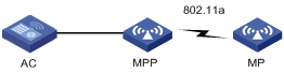
Configuration considerations
The mesh configuration in this example is similar to a common wireless mesh configuration. Note the following guidelines:
· Configure the working channel mode of the radios that provide mesh services as auto.
· Do not configure any wireless service on radios that provide mesh services.
Configuration procedure
The mesh configuration is the same as the normal WLAN mesh configuration. For configuration procedures, see "Normal WLAN mesh configuration example." Perform the following operations after completing mesh configuration:
1. (Optional) Set a calibration interval:
a. Select Radio > Calibration from the navigation tree.
b. Click the Parameters tab.
c. On the page that appears, enter the calibration interval 3 and click OK.
Figure 154 Mesh calibration interval
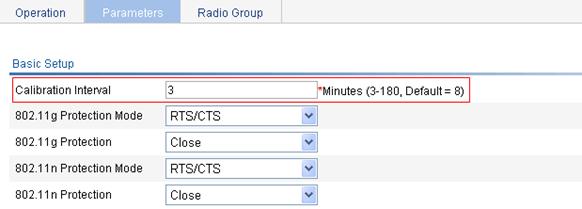
2. Configure mesh DFS:
a. Select Wireless Service > Mesh Service from the navigation tree.
b. Click the Global Setup tab.
c. On the page that appears, select the Manual box for Dynamic Channel Select.
d. Click OK.
Figure 155 DFS
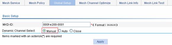
3. Enable one time DFS for the mesh network:
a. Select Wireless Service > Mesh Service from the navigation tree.
b. Click the Mesh Channel Optimize tab.
c. Select the outdoor mesh network.
d. Click Channel Optimize.
Figure 156 One-time mesh DFS
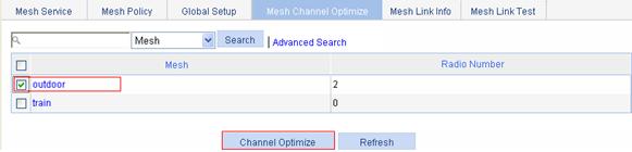
Verifying the configuration
After a next calibration interval, you can view the channel switching information:
1. Select Wireless Service > Mesh Service from the navigation tree.
2. Click the Mesh Channel Optimize tab to enter the Mesh Channel Optimize tab.
3. Click the Channel Info tab.
4. Select the target mesh network to display the radio information.
Figure 157 Displaying mesh channel switching information