- Table of Contents
-
- H3C WX Series Access Controllers Web-Based Configuration Guide(R3308 R2308)-6W107
- 00-Preface
- 01-About the WX Series Access Controllers Web Configuration Guide
- 02-Quick Start
- 03-Web Overview
- 04-Summary
- 05-Device
- 06-Network
- 07-AP Configuration
- 08-Wireless Service
- 09-WLAN Roaming Configuration
- 10-Radio Configuration
- 11-Authentication
- 12-Security
- 13-QoS configuration
- 14-Advanced Settings
- 15-Stateful Failover Configuration
- Related Documents
-
| Title | Size | Download |
|---|---|---|
| 13-QoS configuration | 782.68 KB |
Contents
Recommend configuration procedures
Configuring a rule for a basic IPv4 ACL
Configuring a rule for an advanced IPv4 ACL
Configuring a rule for an Ethernet frame header ACL
Configuring a rule for a basic IPv6 ACL
Configuring a rule for an advanced IPv6 ACL
Configuring the priority trust mode of a port
Recommended QoS policy configuration procedure
Configuring classification rules
Configuring actions for a traffic behavior
Configuring classifier-behavior associations for the policy
Applying a QoS policy to a WLAN service
ACL and QoS configuration example
Setting radio EDCA parameters for APs
Setting client EDCA parameters for wireless clients
Displaying the radio statistics
Displaying the client statistics
Setting wireless service-based client rate limiting
Setting radio-based client rate limiting
Configuring the bandwidth guarantee function
Setting the reference radio bandwidth
Setting guaranteed bandwidth percents
Enabling bandwidth guaranteeing
Displaying guaranteed bandwidth settings
CAC service configuration example
Configuring the wireless service
Wireless service-based static rate limiting configuration example
Configuring the wireless service
Configuring static rate limiting
Wireless service-based dynamic rate limiting configuration example
Configuring the wireless service
Configuring dynamic rate limiting
Bandwidth guarantee configuration example
Configuring the wireless services
Configuring bandwidth guaranteeing
Configuring ACL and QoS
|
|
NOTE: Unless otherwise stated, ACLs refer to both IPv4 and IPv6 ACLs throughout this document. |
ACL overview
An access control list (ACL) is a set of rules (or permit or deny statements) for identifying traffic based on criteria such as source IP address, destination IP address, and port number.
ACLs are essentially used for packet filtering. A packet filter drops packets that match a deny rule and permits packets that match a permit rule. ACLs are also widely used by many modules, for example, QoS and IP routing, for traffic identification.
ACLs fall into the following categories.
|
Category |
ACL number |
IP version |
Match criteria |
|
Basic ACLs |
2000 to 2999 |
IPv4 |
Source IPv4 address |
|
IPv6 |
Source IPv6 address |
||
|
Advanced ACLs |
3000 to 3999 |
IPv4 |
Source/destination IPv4 address, protocols over IPv4, and other Layer 3 and Layer 4 header fields |
|
IPv6 |
Source/destination IPv6 address, protocols over IPv6, and other Layer 3 and Layer 4 header fields |
||
|
Ethernet frame header ACLs |
4000 to 4999 |
IPv4 and IPv6 |
Layer 2 header fields, such as source and destination MAC addresses, 802.1p priority, and link layer protocol type |
|
|
NOTE: For more information about ACL, see ACL and QoS Configuration Guide. |
QoS overview
Quality of Service (QoS) is a concept concerning service demand and supply. It reflects the ability to meet customer needs. Generally, QoS does not focus on grading services precisely, but on improving services under certain conditions.
In the internet, QoS refers to the ability of the network to forward packets. The evaluation on QoS of a network can be based on different aspects because the network may provide various services. Generally, QoS refers to the ability to provide improved service by solving the core issues such as delay, jitter, and packet loss ratio in the packet forwarding process.
Traditional packet forwarding services
On traditional IP networks, devices treat all packets equally and handle them using the first in first out (FIFO) policy. All packets share the resources of the network and devices. How many resources the packets can obtain completely depends on the time they arrive. This service is called "best-effort". It delivers packets to their destinations as possibly as it can, without any guarantee for delay, jitter, packet loss ratio, reliability and so on.
This service policy is only suitable for applications insensitive to bandwidth and delay, such as WWW, file transfer and email.
New requirements from new applications
The Internet has been growing along with the fast development of networking technologies. More and more users take the Internet as their data transmission platform to implement various applications.
Besides traditional applications such as WWW, email and FTP, network users are experiencing new services, such as tele-education, telemedicine, video telephone, videoconference and Video-on-Demand (VoD). The enterprise users expect to connect their regional branches together through VPN technologies to carry out operational applications, for instance, to access the database of the company or to monitor remote devices through Telnet.
These new applications have one thing in common, and they all have special requirements for bandwidth, delay, and jitter. For instance, videoconference and VoD need large bandwidth, low delay and jitter. As for mission-critical applications, such as transactions and Telnet, they may not require large bandwidth but do require low delay and preferential service during congestion.
The new emerging applications demand higher service performance of IP networks. Better network services during packets forwarding are required, such as providing dedicated bandwidth, reducing packet loss ratio, managing and avoiding congestion, regulating network traffic, and setting the precedence of packets. To meet these requirements, networks must provide more improved services.
|
|
NOTE: For more information about QoS, see ACL and QoS Configuration Guide. |
Configuring an ACL
Recommend configuration procedures
Recommended IPv4 ACL configuration procedure
|
Step |
Remarks |
|
Optional. A rule referencing a time range takes effect only during the specified time range. |
|
|
Required. The category of the added ACL depends on the ACL number that you specify. |
|
|
Required. Complete one of the three steps according to the ACL category. |
|
Recommended IPv6 ACL configuration procedure
|
Step |
Remarks |
|
Optional. A rule referencing a time range takes effect only during the specified time range. |
|
|
Required. The category of the added IPv6 ACL depends on the ACL number that you specify. |
|
|
Required. Complete one of the steps according to the ACL category. |
|
Adding a time range
1. Select QoS > Time Range from the navigation tree.
2. Click the Add tab to enter the time range adding page.
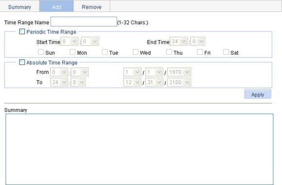
3. Configure the time range information, as described in Table 1.
4. Click Apply.
|
Item |
Description |
||
|
Time Range Name |
Set the name for the time range. |
||
|
Periodic Time Range |
Start Time |
Set the start time of the periodic time range. |
These items are available after you select the Periodic Time Range option. |
|
End Time |
Set the end time of the periodic time range. The end time must be greater than the start time. |
||
|
Sun, Mon, Tue, Wed, Thu, Fri, and Sat. |
Select the day or days of the week on which the periodic time range is valid. You can select any combination of the days of the week. |
||
|
Absolute Time Range |
From |
Set the start time of the absolute time range. The time of the day is in the hh:mm format (24-hour clock), and the date is in the MM/DD/YYYY format. |
These items are available after you select the Absolute Time Range option. |
|
To |
Set the end time of the absolute time range. The time of the day is in the hh:mm format (24-hour clock), and the date is in the MM/DD/YYYY format. The end time must be greater than the start time. |
||
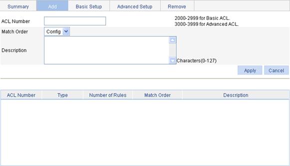
Adding an IPv4 ACL
1. Select QoS > ACL IPv4 from the navigation tree.
2. Click the Add tab to enter the IPv4 ACL adding page, as shown in Figure 2.
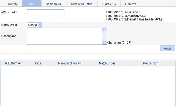
3. Configure the IPv4 ACL information, as described in Table 2.
4. Click Apply.
|
Item |
Description |
|
ACL Number |
Set the number of the IPv4 ACL. |
|
Match Order |
Set the match order of the ACL. Available values are: · Config—Packets are compared against ACL rules in the order that the rules are configured. · Auto—Packets are compared against ACL rules in the depth-first match order. |
|
Description |
Set the description for the ACL. |
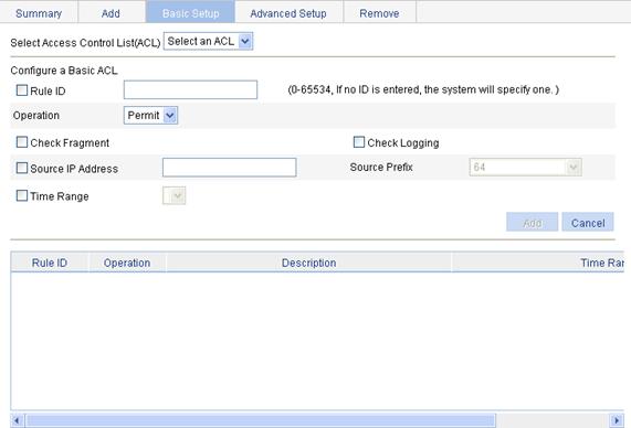
Configuring a rule for a basic IPv4 ACL
1. Select QoS > ACL IPv4 from the navigation tree.
2. Click the Basic Setup tab to enter the rule configuration page for a basic IPv4 ACL, as shown in Figure 3.
Figure 3 Configuring an basic IPv4 ACL
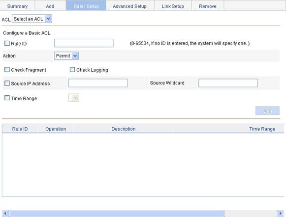
3. Configure a basic IPv4 ACL, as described in Table 3.
4. Click Add.
|
Item |
Description |
|
ACL |
Select the basic IPv4 ACL for which you want to configure rules. Available ACLs are basic IPv4 ACLs. |
|
Rule ID |
Select the Rule ID option and enter a number for the rule. If you do not specify the rule number, the system will assign one automatically.
If the rule number you specify already exists, the following operations modify the configuration of the rule. |
|
Action |
Select the action to be performed for IPv4 packets matching the rule. · Permit—Allows matched packets to pass. · Deny—Drops matched packets. |
|
Check Fragment |
Select this option to apply the rule to only non-first fragments. If you do no select this option, the rule applies to all fragments and non-fragments. |
|
Check Logging |
Select this option to keep a log of matched IPv4 packets. A log entry contains the ACL rule number, operation for the matched packets, protocol that IP carries, source/destination address, source/destination port number, and number of matched packets. |
|
Source IP Address |
Select the Source IP Address option and enter a source IPv4 address and source wildcard, in dotted decimal notation. |
|
Source Wildcard |
|
|
Time Range |
Select the time range during which the rule takes effect. |
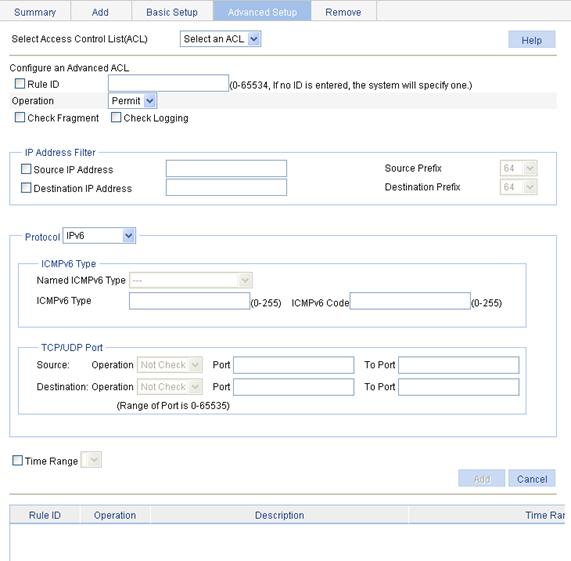
Configuring a rule for an advanced IPv4 ACL
1. Select QoS > ACL IPv4 from the navigation tree.
2. Click the Advanced Setup tab to enter the rule configuration page for an advanced IPv4 ACL, as shown in Figure 4.
Figure 4 Configuring an advanced IPv4 ACL
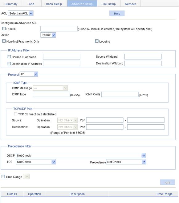
3. Configure an advanced IPv4 ACL rule, as described in Table 4.
4. Click Add.
|
Item |
Description |
||
|
ACL |
Select the advanced IPv4 ACL for which you want to configure rules. Available ACLs are advanced IPv4 ACLs. |
||
|
Rule ID |
Select the Rule ID option and enter a number for the rule. If you do not specify the rule number, the system will assign one automatically.
If the rule number you specify already exists, the following operations modify the configuration of the rule. |
||
|
Action |
Select the action to be performed for IPv4 packets matching the rule. · Permit—Allows matched packets to pass. · Deny—Drops matched packets. |
||
|
Non-First Fragments Only |
Select this option to apply the rule to only non-first fragments. If you do no select this option, the rule applies to all fragments and non-fragments. |
||
|
Logging |
Select this option to keep a log of matched IPv4 packets. A log entry contains the ACL rule number, operation for the matched packets, protocol that IP carries, source/destination address, source/destination port number, and number of matched packets. |
||
|
IP Address Filter |
Source IP Address |
Select the Source IP Address option and enter a source IPv4 address and source wildcard, in dotted decimal notation. |
|
|
Source Wildcard |
|||
|
Destination IP Address |
Select the Source IP Address option and enter a source IP address and source wildcard, in dotted decimal notation. |
||
|
Destination Wildcard |
|||
|
Protocol |
Select the protocol to be carried by IP. If you select 1 ICMP, you can configure the ICMP message type and code; if you select 6 TCP or 17 UDP, you can configure the TCP or UDP specific items. |
||
|
ICMP Type |
ICMP Message |
Specify the ICMP message type and code. These items are available only when you select 1 ICMP from the Protocol list. If you select Other from the ICMP Message list, you must enter values in the ICMP Type and ICMP Code fields. Otherwise, the two fields will take the default values, which cannot be changed. |
|
|
ICMP Type |
|||
|
ICMP Code |
|||
|
TCP/UDP Port |
TCP Connection Established |
Select this option to make the rule match packets used for establishing and maintaining TCP connections. These items are available only when you select 6 TCP from the Protocol list. |
|
|
Source |
Operator |
Select the operators and enter the source port numbers and destination port numbers as required. These items are available only when you select 6 TCP or 17 UDP from the Protocol list. Different operators have different configuration requirements for the port number fields: · Not Check—The following port number fields cannot be configured. · Range—The following port number fields must be configured to define a port range. · Other values—The first port number field must be configured and the second must not. |
|
|
Port |
|||
|
- |
|||
|
Destination |
Operator |
||
|
Port |
|||
|
- |
|||
|
Precedence Filter |
DSCP |
Specify the DSCP value. |
|
|
TOS |
Specify the ToS preference. |
||
|
Precedence |
Specify the IP precedence. |
||
|
Time Range |
Select the time range during which the rule takes effect. |
||
Configuring a rule for an Ethernet frame header ACL
1. Select QoS > ACL IPv4 from the navigation tree.
2. Click the Link Setup tab to enter the rule configuration page for an Ethernet frame header IPv4 ACL, as shown in Figure 5.
Figure 5 Configuring a rule for an Ethernet frame header ACL
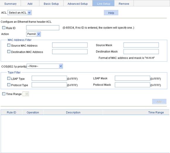
3. Configure an Ethernet frame header IPv4 ACL rule, as described in Table 5.
4. Click Add.
|
Item |
Description |
|
|
ACL |
Select the Ethernet frame header IPv4 ACL for which you want to configure rules. Available ACLs are Ethernet frame header IPv4 ACLs. |
|
|
Rule ID |
Select the Rule ID option and enter a number for the rule. If you do not specify the rule number, the system will assign one automatically.
If the rule number you specify already exists, the following operations modify the configuration of the rule. |
|
|
Action |
Select the action to be performed for IPv4 packets matching the rule. · Permit—Allows matched packets to pass. · Deny—Drops matched packets. |
|
|
MAC Address Filter |
Source MAC Address |
Select the Source MAC Address option and enter a source MAC address and wildcard. |
|
Source Mask |
||
|
Destination MAC Address |
Select the Destination MAC Address option and enter a destination MAC address and wildcard. |
|
|
Destination Mask |
||
|
COS(802.1p priority) |
Specify the 802.1p priority for the rule. |
|
|
Type Filter |
LSAP Type |
Select the LSAP Type option and specify the DSAP and SSAP fields in the LLC encapsulation by configuring the following items: · LSAP Type—Indicates the frame encapsulation format. · LSAP Mask—Indicates the LSAP wildcard.
You can select only one of the LSAP Type option and the Protocol Type option. |
|
LSAP Mask |
||
|
Protocol Type |
Select the Protocol Type option and specify the link layer protocol type by configuring the following items: · Protocol Type—Indicates the frame type. It corresponds to the type-code field of Ethernet_II and Ethernet_SNAP frames. · Protocol Mask—Indicates the wildcard.
You can select only one of the LSAP Type option and the Protocol Type option. |
|
|
Protocol Mask |
||
|
Time Range |
Select the time range during which the rule takes effect. |
|
Adding an IPv6 ACL
1. Select QoS > ACL IPv6 from the navigation tree.
2. Click the Add tab to enter the IPv6 ACL adding page, as shown in Figure 6.
3. Configure the IPv6 ACL information, as described in Table 6.
4. Click Apply.
|
Item |
Description |
|
ACL Number |
Enter a number for the IPv6 ACL. |
|
Match Order |
Select a match order for the ACL. Available values are: · Config—Packets are compared against ACL rules in the order the rules are configured. · Auto—Packets are compared against ACL rules in the depth-first match order. |
|
Description |
Set the description for the ACL. |
Configuring a rule for a basic IPv6 ACL
1. Select QoS > ACL IPv6 from the navigation tree
2. Click the Basic Setup tab to enter the rule configuration page for a basic IPv6 ACL, as shown in Figure 7.
Figure 7 Configuring a rule for a basic IPv6 ACL
3. Configure the basic IPv6 ACL rule information, as described in Table 7.
4. Click Add.
|
Item |
Description |
|
Select Access Control List (ACL) |
Select the basic IPv6 ACL for which you want to configure rules. Available ACLs are basic IPv6 ACLs. |
|
Rule ID |
Select the Rule ID option and enter a number for the rule. If you do not specify the rule number, the system will assign one automatically.
If the rule number you specify already exists, the following operations modify the configuration of the rule. |
|
Operation |
Select the operation to be performed for IPv6 packets matching the rule. · Permit—Allows matched packets to pass. · Deny—Drops matched packets. |
|
Check Fragment |
Select this option to apply the rule to only non-first fragments. If you do no select this option, the rule applies to all fragments and non-fragments. |
|
Check Logging |
Select this option to keep a log of matched IPv6 packets. A log entry contains the ACL rule number, operation for the matched packets, protocol that IP carries, source/destination address, source/destination port number, and number of matched packets. |
|
Source IP Address |
Select the Source IP Address option and enter a source IPv6 address and prefix length. The IPv6 address must be in a format like X:X::X:X. An IPv6 address consists of eight 16-bit long fields, each of which is expressed with two hexadecimal numbers and separated from its neighboring fields by colon (:). |
|
Source Prefix |
|
|
Time Range |
Select the time range during which the rule takes effect. |
Configuring a rule for an advanced IPv6 ACL
1. Select QoS > ACL IPv6 from the navigation tree
2. Click the Advanced Setup tab to enter the rule configuration page for an advanced IPv6 ACL.
Figure 8 Configuring a rule for an advanced IPv6 ACL
3. Configure the advanced IPv6 ACL rule information, as described in Table 8.
4. Click Add.
|
Item |
Description |
||
|
Select Access Control List (ACL) |
Select the advanced IPv6 ACL for which you want to configure rules. Available ACLs are advanced IPv6 ACLs. |
||
|
Rule ID |
Select the Rule ID option and enter a number for the rule. If you do not specify the rule number, the system will assign one automatically.
If the rule number you specify already exists, the following operations modify the configuration of the rule. |
||
|
Operation |
Select the operation to be performed for IPv6 packets matching the rule. · Permit—Allows matched packets to pass. · Deny—Drops matched packets. |
||
|
Check Fragment |
Select this option to apply the rule to only non-first fragments. If you do no select this option, the rule applies to all fragments and non-fragments. |
||
|
Check Logging |
Select this option to keep a log of matched IPv6 packets. A log entry contains the ACL rule number, operation for the matched packets, protocol that IP carries, source/destination address, source/destination port number, and number of matched packets. |
||
|
IP Address Filter |
Source IP Address |
Select the Source IP Address option and enter a source IPv6 address and prefix length. The IPv6 address must be in a format like X:X::X:X. An IPv6 address consists of eight 16-bit long fields, each of which is expressed with two hexadecimal numbers and separated from its neighboring fields by colon (:). |
|
|
Source Prefix |
|||
|
Destination IP Address |
Select the Destination IP Address option and enter a destination IPv6 address and prefix length. The IPv6 address must be in a format like X:X::X:X. An IPv6 address consists of eight 16-bit long fields, each of which is expressed with two hexadecimal numbers and separated from its neighboring fields by colon (:). |
||
|
Destination Prefix |
|||
|
Protocol |
Select the protocol to be carried by IP. If you select 58 ICMPv6, you can configure the ICMP message type and code; if you select 6 TCP or 17 UDP, you can configure the TCP or UDP specific items. |
||
|
ICMPv6 Type |
Named ICMPv6 Type |
Specify the ICMPv6 message type and code. These items are available only when you select 58 ICMPv6 from the Protocol list. If you select Other from the Named ICMPv6 Type list, you must enter values in the ICMPv6 Type and ICMPv6 Code fields. Otherwise, the two fields will take the default values, which cannot be changed. |
|
|
ICMPv6 Type |
|||
|
ICMPv6 Code |
|||
|
TCP/UDP Port |
Source |
Operator |
Select the operators and enter the source port numbers and destination port numbers as required. These items are available only when you select 6 TCP or 17 UDP from the Protocol list. Different operators have different configuration requirements for the port number fields: · Not Check—The following port number fields cannot be configured. · Range—The following port number fields must be configured to define a port range. · Other values—The first port number field must be configured and the second must not. |
|
Port |
|||
|
To Port |
|||
|
Destination |
Operator |
||
|
Port |
|||
|
Port |
|||
|
Time Range |
Select the time range during which the rule takes effect. |
||
Configuring line rate
Line rate uses token buckets to control traffic. The line rate of a physical interface specifies the maximum rate for forwarding packets (including critical packets). Line rate can limit all the packets passing a physical interface.
To configure line rate:
1. Select QoS > Line rate from the navigation tree.
2. Click the Setup tab to enter the line rate configuration page, as shown in Figure 9.
Figure 9 Configuring line rate on a port
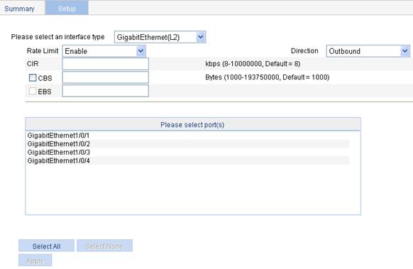
3. Configure line rate, as described in Table 9.
4. Click Apply.
|
Item |
Description |
|
Please select an interface type |
Select the types of interfaces to be configured with line rate. The interface types available for selection depend on your device model. |
|
Rate Limit |
Select Enable or Disable to enable or disable line rate on the specified port. |
|
Direction |
Select a direction in which the line rate is to be applied. · Inbound—Limits the rate of packets received on the specified port. · Outbound—Limits the rate of packets sent by the specified port. |
|
CIR |
Set the committed information rate (CIR), the average traffic rate. |
|
CBS |
Set the committed burst size (CBS), number of bits that can be sent in each interval. |
|
EBS |
Set the excess burst size (EBS). This configuration item is not supported. |
|
Please select port(s) |
Specify the ports to be configured with line rate. Click the ports to be configured with line rate in the port list. You can select one or more ports. |
Configuring the priority trust mode of a port
Priority mapping overview
When a packet enters a device, the device assigns a set of QoS priority parameters to the packet based on a certain priority field carried in the packet and sometimes may modify its priority, according to certain rules depending on device status. This process is called "priority mapping". The set of QoS priority parameters decides the scheduling priority and forwarding priority of the packet.
The device provides various types of priority mapping tables, or rather, priority mappings. By looking up a priority mapping table, the device decides which priority value is to assign to a packet for subsequent packet processing.
You can configure priority mapping by configuring trusting packet priority or trusting port priority.
· If packet priority is trusted, the device uses the specified priority field of the incoming packet to look up the priority mapping tables for the set of QoS priority parameters to assign to the packet. Note that, if a received packet does not carry the specified priority field, the device uses the port priority to look up the priority mapping tables for the set of QoS priority parameters to assign to the packet.
· If port priority is trusted, the device uses the port priority rather than packet priority to look up the priority mapping tables for the set of QoS priority parameters to assign to the packet.
Configuring priority mapping
Two approaches are available for you to configure the priority trust mode on a port for priority mapping:
· In the first approach, you can configure a port to use the 802.1p or 802.11e priority carried in received packets for priority mapping. This approach is supported for the WLAN-ESS interface in addition to other types of interface.
· In the second approach, more options are available. In addition, you can change port priority (local precedence) of a port for priority mapping. This approach is not supported on the WLAN-ESS interface.
Approach 1
1. Select QoS > Trust Mode from the navigation tree to enter the priority trust mode configuration page, as shown in Figure 10.
Figure 10 Configuring priority trust mode
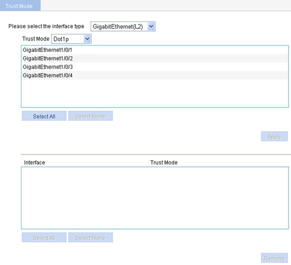
2. Configure the priority trust mode of the interfaces, as described in Table 10.
3. Click Apply.
|
Item |
Description |
|
Please select the interface type |
Select the type of the ports to be configured. The interface types available for selection depend on your device model.
If a WLAN-ESS interface in use has WLAN-DBSS interfaces created on it, its priority cannot be modified. To modify the priority of the WLAN-ESS interface, you must stop the service the interface provides (make the current users on the interface offline). |
|
Trust Mode |
Select the priority trust mode: · Dot1p—Uses the 802.1p priority of received packets for mapping. · Dscp—Uses the DSCP value of received packets for mapping. · Dot11e—Uses the 802.11e priority of received packets for mapping. This option is applicable to only WLAN-ESS interfaces.
Support for priority trust modes depends on the interface type. The supported priority trust modes are shown in the Trust Mode list. |
|
(Select the ports) |
Specify the ports to be configured. Click the ports to be configured in the port list. You can select one or more ports. |
Approach 2
1. Select QoS > Port Priority from the navigation tree to enter the page shown in Figure 11.
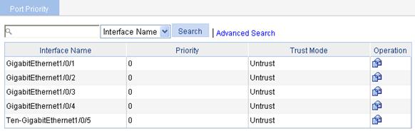
2.
Click the ![]() icon for
a port to enter the page for configuring the priority and priority trust mode
of the port, as shown in Figure
12.
icon for
a port to enter the page for configuring the priority and priority trust mode
of the port, as shown in Figure
12.
Figure 12 Modify the port priority
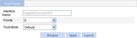
3. Set the port priority, as described in Table 11.
4. Click Apply.
|
Item |
Remarks |
|
Interface Name |
Name of the interface to be configured. |
|
Priority |
Set the local precedence value for the port. Local precedence is allocated by the device and has only local significance. A local precedence value corresponds to an output queue. A packet with higher local precedence is assigned to a higher priority output queue to be preferentially scheduled. |
|
Trust Mode |
Set the priority trust mode of the port: · Untrust—Uses the port priority rather than a packet priority value for priority mapping. · Dot1p—Uses the 802.1p priority of received packets for priority mapping. · DSCP—Uses the DSCP value of received packets for priority mapping.
Support for priority trust modes depends on the interface type. |
Configuring a QoS policy
Recommended QoS policy configuration procedure
A QoS policy defines what QoS actions to take on what class of traffic for purposes such as traffic shaping or traffic policing. Before configuring a QoS policy, be familiar with these concepts: class, traffic behavior, and policy.
Class
Classes identify traffic.
A class is identified by a class name and contains some match criteria for identifying traffic. The relationship between the criteria can be:
· AND—A packet is considered belonging to a class only when the packet matches all the criteria in the class.
· OR—A packet is considered belonging to a class if it matches any of the criteria in the class.
Traffic behavior
A traffic behavior, identified by a name, defines a set of QoS actions for packets.
Policy
A policy associates a class with a traffic behavior to define what actions to take on which class of traffic.
You can define multiple class-traffic behavior associations in a policy.
You can apply a policy to a port to regulate traffic sent or received on the port. A QoS policy can be applied to multiple ports, but in one direction (inbound or outbound) of a port, only one QoS policy can be applied.
|
Step |
Remarks |
|
Required. Add a class and specify the operator of the class. |
|
|
Required. Configure match criteria for the class. |
|
|
Required. Add a traffic behavior. |
|
|
Use either approach. Configure various actions for the traffic behavior. |
|
|
Required. Add a policy. |
|
|
6. Configuring classifier-behavior associations for the policy |
Required. Associate a traffic behavior with a class in the QoS policy. You can associate a class with only one traffic behavior in a QoS policy. If a class is associated with multiple traffic behaviors, the last associated one takes effect. |
|
7. Apply the policy |
Use either approach. Apply the QoS policy to a port or a WLAN service. |
Adding a class
1. Select QoS > Classifier from the navigation tree.
2. Click the Add tab to enter the page for adding a class, as shown in Figure 13.

3. Configure the class information, as described in Table 12.
4. Click Add.
|
Item |
Description |
|
Classifier Name |
Specify a name for the classifier to be added. |
|
Operator |
Specify the logical relationship between rules of the classifier. · And—Specifies the relationship between the rules in a class as logic AND. The device considers a packet belongs to a class only when the packet matches all the rules in the class. · Or—Specifies the relationship between the rules in a class as logic OR. The device considers a packet belongs to a class as long as the packet matches one of the rules in the class. |
Configuring classification rules
1. Select QoS > Classifier from the navigation tree.
2. Click the Setup tab to enter the page for setting a class, as shown in Figure 14.
Figure 14 Configuring classification rules
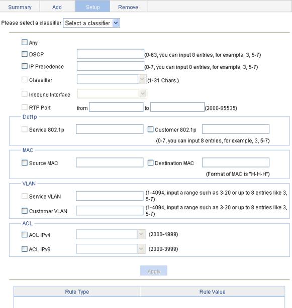
3. Configuration classification rules, as described in Table 13.
4. Click Apply.
A progress dialog box appears.
5. Click Close on the progress dialog box when the progress dialog box prompts that the configuration succeeds.
|
Item |
Description |
|
|
Please select a classifier |
Select an existing classifier in the list. |
|
|
Any |
Define a rule to match all packets. Select the option to match all packets. |
|
|
DSCP |
Define a rule to match DSCP values. If multiple such rules are configured for a class, the new configuration does not overwrite the previous one. You can configure up to eight DSCP values each time. If multiple identical DSCP values are specified, the system considers them as one. The relationship between different DSCP values is OR. After such configurations, all the DSCP values are arranged in ascending order automatically. |
|
|
IP Precedence |
Define a rule to match IP precedence values. If multiple such rules are configured for a class, the new configuration does not overwrite the previous one. You can configure up to eight IP precedence values each time. If multiple identical IP precedence values are specified, the system considers them as one. The relationship between different IP precedence values is OR. After such configurations, all the IP precedence values are arranged in ascending order automatically. |
|
|
Classifier |
Define a rule to match a QoS class.
This configuration item is not supported. |
|
|
Inbound Interface |
Define a rule to match inbound interfaces.
This configuration item is not supported. |
|
|
RTP Port |
Define a rule to match a range of RTP ports. Specify the start port in the from field and the end port in the to field.
This configuration item is not supported. |
|
|
Dot1p |
Service 802.1p |
Define a rule to match the service 802.1p precedence values. If multiple such rules are configured for a class, the new configuration does not overwrite the previous one. You can configure up to eight Dot1p values each time. If multiple identical Dot1p values are specified, the system considers them as one. The relationship between different Dot1p values is OR. After such configurations, all the Dot1p values are arranged in ascending order automatically.
This configuration item is not supported. |
|
Customer 802.1p |
Define a rule to match the customer 802.1p precedence values. If multiple such rules are configured for a class, the new configuration does not overwrite the previous one. You can configure up to eight Dot1p values each time. If multiple identical Dot1p values are specified, the system considers them as one. The relationship between different Dot1p values is OR. After such configurations, all the Dot1p values are arranged in ascending order automatically. |
|
|
MAC |
Source MAC |
Define a rule to match a source MAC address. If multiple such rules are configured for a class, the new configuration does not overwrite the previous one. A rule to match a source MAC address is significant only to Ethernet interfaces. |
|
Destination MAC |
Define a rule to match a destination MAC address. If multiple such rules are configured for a class, the new configuration does not overwrite the previous one. A rule to match a destination MAC address is significant only to Ethernet interfaces. |
|
|
VLAN |
Service VLAN |
Define a rule to match service VLAN IDs. If multiple such rules are configured for a class, the new configuration does not overwrite the previous one. You can configure multiple VLAN IDs each time. If the same VLAN ID is specified multiple times, the system considers them as one. The relationship between different VLAN IDs is logical OR. After such a configuration. You can specify VLAN IDs in two ways: · Enter a range of VLAN IDs, such as 10-500. The number of VLAN IDs in the range is not limited. · Specify a combination of individual VLAN IDs and VLAN ID ranges, such as 3, 5-7, 10. You can specify up to eight VLAN IDs in this way.
This configuration item is not supported. |
|
Customer VLAN |
Define a rule to match customer VLAN IDs. If multiple such rules are configured for a class, the new configuration does not overwrite the previous one. You can configure multiple VLAN IDs each time. If the same VLAN ID is specified multiple times, the system considers them as one. The relationship between different VLAN IDs is logical OR. You can specify VLAN IDs in two ways: · Enter a range of VLAN IDs, such as 10-500. The number of VLAN IDs in the range is not limited. · Specify a combination of individual VLAN IDs and VLAN ID ranges, such as 3, 5-7, 10. You can specify up to eight VLAN IDs in this way. |
|
|
ACL |
ACL IPv4 |
Define an IPv4 ACL-based rule. |
|
ACL IPv6 |
Define an IPv6 ACL-based rule. |
|
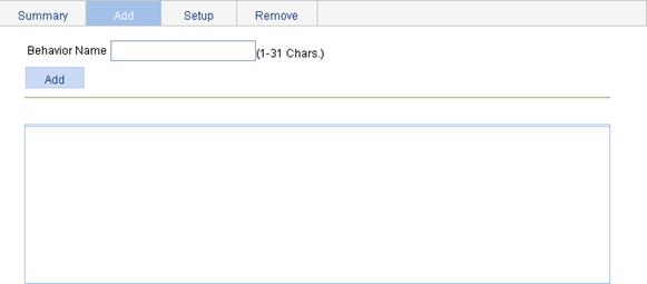
Adding a traffic behavior
1. Select QoS > Behavior from the navigation tree.
2. Click the Add tab to enter the page for adding a traffic behavior, as shown in Figure 15.
3. Set the traffic behavior name.
4. Click Add.
Figure 15 Adding a traffic behavior
Configuring actions for a traffic behavior
1. Select QoS > Behavior from the navigation tree.
2. Click the Setup tab to enter the page for setting a traffic behavior, as shown in Figure 16.
Figure 16 Setting a traffic behavior
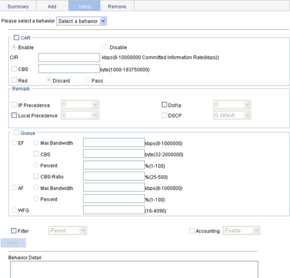
3. Configure the traffic behavior actions, as described in Table 14.
4. Click Apply.
A progress dialog box appears.
5. Click Close on the progress dialog box when the progress dialog box prompts that the configuration succeeds.
|
Item |
Description |
|||
|
Please select a behavior |
Select an existing behavior in the list. |
|||
|
CAR |
Enable/Disable |
Enable or disable CAR |
||
|
CIR |
Set the committed information rate (CIR), the average traffic rate. |
|||
|
CBS |
Set the committed burst size (CBS), number of bits that can be sent in each interval. |
|||
|
Red |
Discard |
Set the action to perform for exceeding packets. After selecting the Red option, you can select one of the following options: · Discard—Drops the exceeding packet. · Pass—Permits the exceeding packet to pass through. |
||
|
Pass |
||||
|
Remark |
IP Precedence |
Configure the action of marking IP precedence for packets. Select the IP Precedence option and then select the IP precedence value to be marked for packets in the following list. Select Not Set to cancel the action of marking IP precedence.
This configuration item is not supported. |
||
|
Dot1p |
Configure the action of marking 802.1p precedence for packets. Select the Dot1p option and then select the 802.1p precedence value to be marked for packets in the following list. Select Not Set to cancel the action of marking 802.1p precedence. |
|||
|
Local Precedence |
Configure the action of marking local precedence for packets. Select the Local Precedence option and then select the local precedence value to be marked for packets in the following list. Select Not Set to cancel the action of marking local precedence. |
|||
|
DSCP |
Configure the action of marking DSCP values for packets. Select the DSCP option and then select the DSCP value to be marked for packets in the following list. Select Not Set to cancel the action of marking DSCP values.
This configuration item is not supported. |
|||
|
Queue |
EF |
Max Bandwidth |
Configure the maximum bandwidth for expedited forwarding (EF). |
These configuration items are not supported. |
|
CBS |
Configure the CBS for EF. |
|||
|
Percent |
Configure the percent of available bandwidth for EF. |
|||
|
CBS-Ratio |
Configure the ratio of CBS to CIR for EF. |
|||
|
AF |
Min Bandwidth |
Configure the minimum guaranteed bandwidth for assured forwarding (AF). |
||
|
Percent |
Configure the percent of available bandwidth for AF. |
|||
|
WFQ |
Configure WFQ for the default class by entering the total number of fair queues, which must be the power of two. |
|||
|
Filter |
Configure the packet filtering action. After selecting the Filter option, select one item in the following list: · Permit—Forwards the packet. · Deny—Drops the packet. · Not Set—Cancels the packet filtering action. |
|||
|
Accounting |
Configure the traffic accounting action. Select the Accounting option and select Enable or Disable in the following list to enable/disable the traffic accounting action.
This configuration item is not supported. |
|||
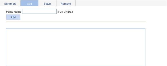
Adding a policy
1. Select QoS > QoS Policy from the navigation tree.
2. Click the Add tab to enter the page for adding a policy, as shown in Figure 17.
3. Set the policy name.
4. Click Add.
Configuring classifier-behavior associations for the policy
1. Select QoS > QoS Policy from the navigation tree.
2. Click the Setup tab to enter the page for setting a policy, as shown in Figure 18.
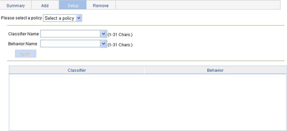
3. Configure classifier-behavior associations, as described in Table 15.
4. Click Apply.
|
Item |
Description |
|
Please select a policy |
Select an existing policy in the list. |
|
Classifier Name |
Select an existing classifier in the list. |
|
Behavior Name |
Select an existing behavior in the list. |
Applying a policy to a port
1. Select QoS > Port Policy from the navigation tree.
2. Click the Setup tab to enter the page for applying a policy to a port, as shown in Figure 19.
Figure 19 Applying a policy to a port
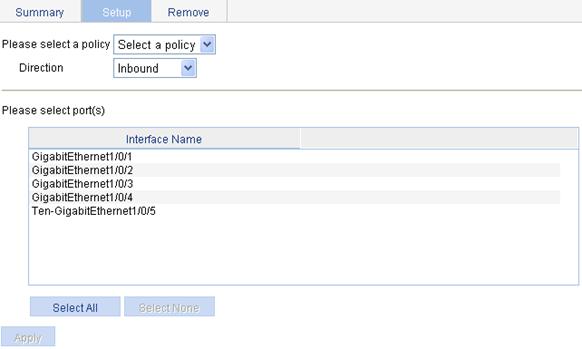
3. Select a policy and apply the policy to the specified ports, as described in Table 16.
4. Click Apply.
|
Item |
Description |
|
Please select a policy |
Select an existing policy in the list. |
|
Direction |
Set the direction in which you want to apply the policy. · Inbound—Applies the policy to the incoming packets of the specified ports. · Outbound—Applies the policy to the outgoing packets of the specified ports. |
|
Please select port(s) |
Click the ports to which the QoS policy is to be applied in the port list. You can select one or more ports. |
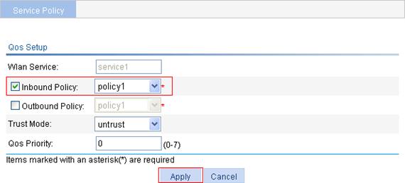
Applying a QoS policy to a WLAN service
1. Select QoS > Service Policy from the navigation tree to enter the service policy page shown in Figure 20.
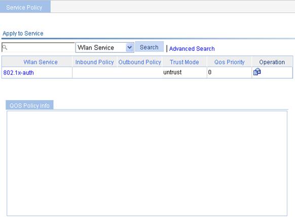
2.
Click the ![]() icon for
a wireless service to enter the service policy setup page shown in Figure 20.
icon for
a wireless service to enter the service policy setup page shown in Figure 20.
Figure 21 Service policy setup
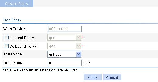
3. Apply the policy to the wireless service, as described in Table 17.
4. Click Apply.
|
Item |
Remarks |
|
Wlan Service |
Display the specified WLAN service to which you want to apply a QoS policy. |
|
Inbound Policy |
Apply the QoS policy to the packets received by the wireless service. |
|
Outbound Policy |
Apply the QoS policy to the packets sent by the wireless service. |
|
Trust Mode |
Set the priority trust mode: · Untrust—Trusts the port priority. · Dscp—Uses the DSCP values of received packets for mapping. · 802.11e—Uses the 802.11e priority of received 802.11 packets for mapping. |
|
QoS Priority |
Set the local precedence value. |
ACL and QoS configuration example
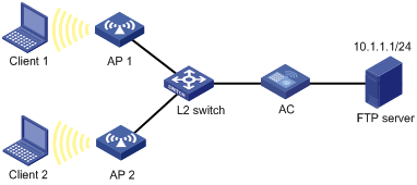
Network requirements
As shown in Figure 22, in the WLAN, the FTP server (10.1.1.1/24) is connected to the AC (SSID: service1), and the wireless clients are connected to the AC through APs and a Layer 2 switch and access the network resources.
Configure an ACL and a QoS policy on the AC to prohibit the wireless clients from accessing the FTP server from 8:00 to 18:00 every day:
1. Add an ACL to prohibit the hosts from accessing the FTP server from 8:00 to 18:00 every day.
2. Configure a QoS policy to drop the packets matching the ACL.
3. Apply the QoS policy in the inbound direction of the wireless service named service1.
Configuration procedure
|
|
NOTE: Before performing the following configurations, make sure the AC has been configured with wireless service service1. For more information about the wireless service configuration, see "Configuring access services." |
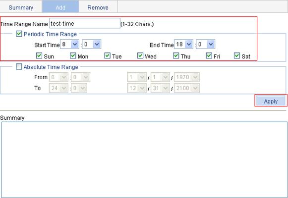
1. Define a time range to cover the time range from 8:00 to 18:00 every day:
a. Select QoS > Time Range from the navigation tree.
b. Click the Add tab.
c. On the page as shown in Figure 23, enter the time range name test-time, select the Periodic Time Range option, set the Start Time to 8:00 and the End Time to 18:00, and select the options Sun through Sat.
d. Click Apply.
Figure 23 Defining a time range covering 8:00 to 18:00 every day
2. Add an advanced IPv4 ACL:
a. Select QoS > ACL IPv4 from the navigation tree.
b. Click the Add tab.
c. Enter the ACL number 3000.
d. Click Apply.
Figure 24 Adding an advanced IPv4 ACL

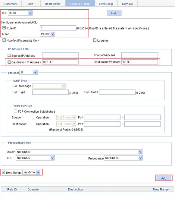
3. Define an ACL rule for traffic to the FTP server:
a. Click the Advanced Setup tab.
b. On the page as shown in Figure 25, select 3000 in the ACL list, select the Rule ID option, and enter rule ID 2.
c. Select Permit in the Action list.
d. Select the Destination IP Address option, and enter IP address 10.1.1.1 and destination wildcard 0.0.0.0.
e. Select test-time in the Time Range list.
f. Click Add.
Figure 25 Defining an ACL rule for traffic to the FTP server
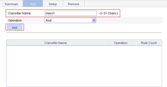
4. Add a class:
a. Select QoS > Classifier from the navigation tree.
b. Click the Add tab.
c. On the page as shown in Figure 26, enter the class name class1.
d. Click Add.
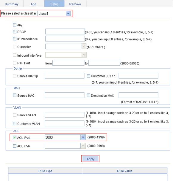
5. Define classification rules:
a. Click the Setup tab.
b. On the page as shown in Figure 27, select the class name class1 in the list, select the ACL IPv4 option, and select ACL 3000 in the following list.
c. Click Apply.
A progress dialog box appears.
d. Click Close on the progress dialog box when the progress dialog box prompts that the configuration succeeds.
Figure 27 Defining classification rules
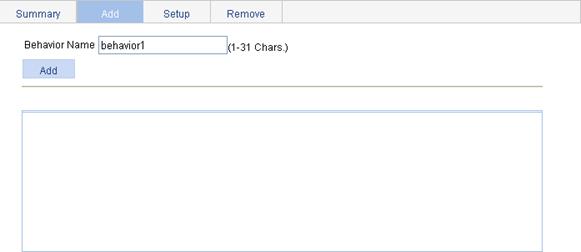
6. Add a traffic behavior:
a. Select QoS > Behavior from the navigation tree.
b. Click the Add tab.
c. On the page as shown in Figure 28, enter the behavior name behavior1.
d. Click Add.
Figure 28 Adding a traffic behavior
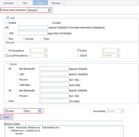
7. Configure actions for the traffic behavior:
a. Click the Setup tab.
b. On the page as shown in Figure 29, select behavior1 in the list, select the Filter option, and then select Deny in the following list.
c. Click Apply.
A progress dialog box appears.
d. Click Close when the progress dialog box prompts that the configuration succeeds.
Figure 29 Configuring actions for the behavior
8. Add a policy:
a. Select QoS > QoS Policy from the navigation tree.
b. Click the Add tab.
c. On the page as shown in Figure 30, enter the policy name policy1.
d. Click Add.

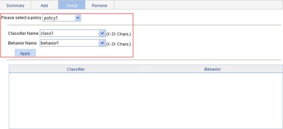
9. Configure classifier-behavior associations for the policy:
a. Click the Setup tab.
b. On the page as shown in Figure 31, select policy1, select class1 in the Classifier Name list, and select behavior1 in the Behavior Name list.
c. Click Apply.
Figure 31 Configuring classifier-behavior associations for the policy
10. Apply the QoS policy in the inbound direction of the wireless service named service1:
a. Select QoS > Service Policy from the navigation tree.
b. Click the ![]() icon for wireless service service1.
icon for wireless service service1.
c. On the page as shown in Figure 32, select the Inbound Policy option, and select policy1 from the following list.
d. Click Apply.
Figure 32 Applying the QoS policy in the inbound direction of WLAN service service1
Verifying the configuration
After you complete these configurations, the QoS policy is successfully applied to the wireless service named service1, and the wireless clients cannot access the FTP server at IP address 10.1.1.1/24 from 8:00 to 18:00 every day, but they can do that at any other time.
Configuration guidelines
When you configure an ACL and QoS, follow these guidelines:
· You cannot add a ACL rule with, or modify a rule to have, the same permit/deny statement as an existing rule in the ACL.
· You can only modify the existing rules of an ACL that uses the match order of config. When modifying a rule of such an ACL, you may choose to change just some of the settings, in which case the other settings remain the same.
· When you configure line rate and traffic policing for a behavior, make sure the ratio of CBS to CIR is more than 100:16. Otherwise, the handling for bursty traffic may be affected.
· If an ACL is referenced by a QoS policy for defining traffic classification rules, the operation of the QoS policy varies by interface (the definition of software/hardware interface varies with device models). The specific process is as follows:
¡ If the QoS policy is applied to a software interface and the referenced ACL rule is a deny clause, the ACL rule does not take effect and packets go to the next classification rule.
¡ If the QoS policy is applied to a hardware interface, packets matching the referenced ACL rule are organized as a class and the behavior defined in the QoS policy applies to the class regardless of whether the referenced ACL rule is a deny or permit clause.
· If a QoS policy is applied in the outbound direction of a port, the QoS policy cannot influence local packets. Local packets refer to the important protocol packets that maintain the normal operation of the device. QoS must not process such packets to avoid packet drop. Commonly used local packets are: link maintenance packets, ISIS packets, OSPF packets, RIP packets, BGP packets, LDP packets, RSVP packets, and SSH packets and so on.
· When you configure queuing for a traffic behavior:
¡ In a policy, a traffic behavior with EF configured cannot be associated with the default class, and a traffic behavior with WFQ configured can only be associated with the default class.
¡ In a policy, the total bandwidth assigned to the AF and EF classes cannot be greater than the available bandwidth of the interface to which the policy applies; the total bandwidth percentage assigned to the AF and EF classes cannot be greater than 100%.
¡ In the same policy, the same bandwidth unit must be used to configure bandwidth for AF classes and EF classes, either absolute bandwidth value or percent.
Configuring wireless QoS
Overview
An 802.11 network offers wireless access based on the carrier sense multiple access with collision avoidance (CSMA/CA) channel contention. All clients accessing the WLAN have equal channel contention opportunities, and all applications carried on the WLAN use the same channel contention parameters. A live WLAN, however, is required to provide differentiated access services to address diversified requirements of applications for bandwidth, delay, and jitter.
When IEEE 802.11e was being standardized, Wi-Fi Alliance defined the Wi-Fi Multimedia (WMM) standard to allow QoS provision devices of different vendors to interoperate. WMM makes a WLAN network capable of providing QoS services.
Terminology
WMM
WMM is a wireless QoS protocol designed to preferentially transmit packets with high priority, and guarantees better QoS services for voice and video applications in a wireless network.
EDCA
Enhanced distributed channel access (EDCA) is a channel contention mechanism designed by WMM to preferentially transmit packets with high priority and allocate more bandwidth to such packets.
AC
WMM uses access categories (ACs) for handling channel contentions. WMM assigns WLAN data into four access categories: AC-VO (voice), AC-VI (video), AC-BE (best-effort), and AC-BK (background), in the descending order of priority. Each access category uses an independent priority queue for transmitting data. When contention occurs, WMM guarantees that a high-priority access category preempts a low-priority access category.
CAC
Connection admission control (CAC) limits the number of clients that are using high-priority access categories (AC-VO and AC-VI) to guarantee sufficient bandwidth for existing high-priority traffic.
U-APSD
Unscheduled automatic power-save delivery (U-APSD) is a new power saving mechanism defined by WMM to enhance the power saving capability of clients.
SVP
SpectraLink voice priority (SVP) is a voice priority protocol designed by the Spectralink company to guarantee QoS for voice traffic.
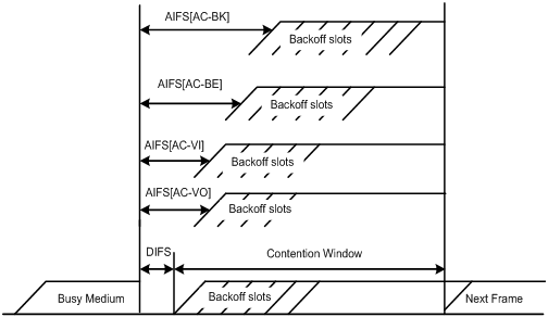
WMM protocol overview
The distributed coordination function (DCF) in 802.11 stipulates that access points (APs) and clients use the CSMA/CA access mechanism. APs or clients listen to the channel before they hold the channel for data transmission. When the specified idle duration of the channel times out, APs or clients randomly select a backoff slot within the contention window to perform backoff. The device that finishes backoff first gets the channel. With 802.11, all devices have the same idle duration and contention window. They are equal when contending for a channel. In WMM, this fair contention mechanism is changed.
EDCA parameters
WMM assigns data packets to four access categories. By allowing a high-priority access category to have more channel contention opportunities than a low-priority access category, WMM offers different service levels to access categories.
WMM define a set of EDCA parameters for each access category, covering the following:
· Arbitration inter-frame spacing number (AIFSN)—Different from the 802.11 protocol where the idle duration (set using DIFS) is a constant value, WMM can define an idle duration per access category. The idle duration increases as the AIFSN value increases (see Figure 33 for the AIFS durations).
· Exponent of CWmin (ECWmin) and exponent of CWmax (ECWmax)—Determine the average backoff slots, which increases as the two values increase (see Figure 33 for the backoff slots).
· Transmission opportunity limit (TXOPLimit)—Indicates the maximum time for which a user can hold a channel after a successful contention. The greater the TXOPLimit is, the longer the user can hold the channel. The value 0 indicates that the user can send only one packet each time it holds the channel.
Figure 33 Per-AC channel contention parameters in WMM
CAC admission policies
CAC requires that a client obtain permission of the AP before it can use a high-priority access category for transmission, and guarantees bandwidth to the clients that have gained access. CAC controls real time traffic (AC-VO and AC-VI traffic) but not common data traffic (AC-BE and AC-BK traffic).
To use a high-priority access category, a client must send a request to the AP. The AP returns a positive or negative response based on either of the following admission control policy:
· Channel utilization-based admission policy—The AP calculates the total time that the existing high-priority access categories occupy the channel in one second, and then calculates the time that the requesting traffic will occupy the channel in one second. If the sum of the two values is smaller than or equal to the maximum hold time of the channel, the client can use the requested access category. Otherwise, the request is rejected.
· Users-based admission policy—If the number of clients using high-priority access categories plus the requesting clients is smaller than or equal to the maximum number of high-priority access category clients, the request is accepted. Otherwise, the request is rejected. During calculation, a client is counted once even if it is using both AC-VO and AC-VI.
U-APSD power-save mechanism
U-APSD improves the 802.11 APSD power saving mechanism. When associating clients with access categories, specify some access categories as trigger-enabled, some access categories as delivery-enabled, and the maximum number of data packets that can be delivered after receiving a trigger packet. Both the trigger attribute and the delivery attribute can be modified when flows are established using CAC. When a client sleeps, the delivery-enabled AC packets destined for the client are buffered. The client needs to send a trigger-enabled AC packet to get the buffered packets. After the AP receives the trigger packet, packets in the transmit queue are sent. The number of sent packets depends on the agreement made when the client was admitted. Access categories without the delivery attribute store and transmit packets as defined in the 802.11 protocol.
SVP service
SVP service implements differentiated treatment of SVP packets by mapping each SVP packet (IP protocol number 119) to an access category, which corresponds to a transmit queue with certain priority.
ACK policy
WMM defines the following ACK policies:
· No ACK—When the no acknowledgement (No ACK) policy is used, the recipient does not acknowledge received packets during wireless packet exchange. This policy can improve transmission efficiency in the environment where communication quality is fine and interference is weak. However, in the environment where communication quality is poor, it can cause increased packet loss and deteriorated communication quality.
· Normal ACK—When the Normal ACK policy is used, the recipient acknowledges each received unicast packet.
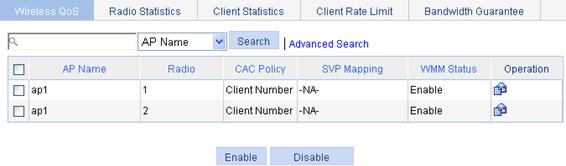
Enabling wireless QoS
1. Select QoS > Wireless QoS from the navigation tree.
By default, the Wireless QoS tab is displayed, as shown in Figure 34.
2. Select the option in front of the radio unit to be configured.
3. Click Enable.
By default, wireless QoS is enabled.
|
|
NOTE: The WMM protocol is the foundation of the 802.11n protocol. When the radio works in 802.11n (5 GHz) or 802.11n (2.4 GHz) radio mode, you must enable WMM. Otherwise, the associated 802.11n clients may fail to communicate. |
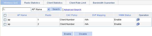
Setting the SVP service
|
|
NOTE: SVP mapping is applicable only to non-WMM clients. |
1. Select QoS > Wireless QoS from the navigation tree.
By default, the Wireless QoS tab is displayed, as shown in Figure 35.
Figure 35 Mapping SVP service to an access category
2.
Click the ![]() icon in the Operation column for the desired AP to enter the page for mapping SVP service
to an access category, as shown in Figure 36.
icon in the Operation column for the desired AP to enter the page for mapping SVP service
to an access category, as shown in Figure 36.
Figure 36 Mapping SVP service to an access category

3. Configure SVP mapping, as described in Table 18.
4. Click Apply.
|
Item |
Description |
|
AP Name |
Displays the selected AP. |
|
Radio |
Displays the selected AP's radio. |
|
SVP Mapping |
Select the option before SVP Mapping, and then select an access category for SVP service: · AC-VO. · AC-VI. · AC-BE. · AC-BK. |
Setting CAC admission policy
1. Select QoS > Wireless QoS from the navigation tree.
By default, the Wireless QoS tab is displayed.
2.
Click the ![]() icon
in the Operation column for the desired AP to enter the page for setting CAC
admission policy, as shown in Figure 37.
icon
in the Operation column for the desired AP to enter the page for setting CAC
admission policy, as shown in Figure 37.
Figure 37 Setting CAC admission policy
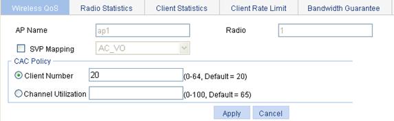
3. Configure the CAC admission policy, as described in Table 19.
4. Click Apply.
|
Item |
Description |
|
Client Number |
Users-based admission policy, or the maximum number of clients allowed to be connected. A client is counted only once, even if it is using both AC-VO and AC-VI. By default, the users-based admission policy applies, with the maximum number of users being 20. |
|
Channel Utilization |
Channel utilization-based admission policy, or the rate of the medium time of the accepted AC-VO and AC-VI traffic to the valid time during the unit time. The valid time is the total time during which data is transmitted. |
Setting radio EDCA parameters for APs
1. Select QoS > Wireless QoS from the navigation tree.
By default, the Wireless QoS tab is displayed.
2.
Click the ![]() icon
in the Operation column for the desired AP to enter the page for configuring
wireless QoS.
icon
in the Operation column for the desired AP to enter the page for configuring
wireless QoS.
3.
On the radio EDCA list, click the ![]() icon
in the Operation column for the desired priority type (AC_BK, for example) to enter
the page for setting radio EDCA parameters.
icon
in the Operation column for the desired priority type (AC_BK, for example) to enter
the page for setting radio EDCA parameters.
Figure 38 Setting radio EDCA parameters
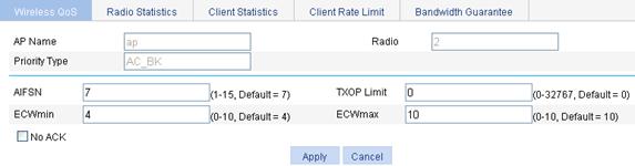
4. Configure the radio EDCA parameters, as described in Table 20.
5. Click Apply.
|
Item |
Description |
|
AP Name |
Displays the selected AP. |
|
Radio |
Displays the selected AP's radio. |
|
Priority type |
Displays the priority type. |
|
AIFSN |
Arbitration inter-frame spacing number used by the AP. |
|
TXOP Limit |
Transmission opportunity limit used by the AP. |
|
ECWmin |
Exponent of CWmin used by the AP. |
|
ECWmax |
Exponent of CWmax used by the AP. |
|
No ACK |
If you select the option before No ACK, the No ACK policy is used by the AP. By default, the normal ACK policy is used by the AP. |
Table 21 Default radio EDCA parameters
|
Access category |
AIFSN |
ECWmin |
ECWmax |
|
|
AC-BK |
0 |
7 |
4 |
10 |
|
AC-BE |
0 |
3 |
4 |
6 |
|
AC-VI |
94 |
1 |
3 |
4 |
|
AC-VO |
47 |
1 |
2 |
3 |
|
|
NOTE: · ECWmin cannot be greater than ECWmax. · On an AP operating in 802.11b radio mode, H3C recommends that you set the TXOP-Limit to 0, 0, 188, and 102 for AC-BK, AC-BE, AC-VI, and AC-VO. |
Setting client EDCA parameters for wireless clients
1. Select QoS > Wireless QoS from the navigation tree.
By default, the Wireless QoS tab is displayed.
2.
Click the ![]() icon
in the Operation column for the desired AP to enter the page for configuring
wireless QoS.
icon
in the Operation column for the desired AP to enter the page for configuring
wireless QoS.
3.
On the client EDCA list, click the ![]() icon
in the Operation column for the desired priority type (AC_BK, for example) to enter
the page for setting client EDCA parameters.
icon
in the Operation column for the desired priority type (AC_BK, for example) to enter
the page for setting client EDCA parameters.
Figure 39 Setting client EDCA parameters
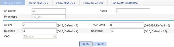
4. Configure the client EDCA parameters, as described in Table 22.
5. Click Apply.
|
Item |
Description |
|
AP Name |
Displays the selected AP. |
|
Radio |
Displays the selected AP's radio. |
|
Priority type |
Displays the priority type. |
|
AIFSN |
Arbitration inter-frame spacing number used by clients. |
|
TXOP Limit |
Transmission opportunity limit used by clients. |
|
ECWmin |
Exponent of CWmin used by clients. |
|
ECWmax |
Exponent of CWmax used by clients. |
|
CAC |
Enable CAC: · Enable—Enable CAC. · Disable—Disable CAC. AC-VO and AC-VI support CAC, which is disabled by default. This item is not available for AC-BE or AC-BK, because they do not support CAC. |
Table 23 Default EDCA parameters for clients
|
Access category |
TXOP Limit |
AIFSN |
ECWmin |
ECWmax |
|
AC-BK |
0 |
7 |
4 |
10 |
|
AC-BE |
0 |
3 |
4 |
10 |
|
AC-VI |
94 |
2 |
3 |
4 |
|
AC-VO |
47 |
2 |
2 |
3 |
|
|
NOTE: · ECWmin cannot be greater than ECWmax. · If all clients operate in 802.11b radio mode, set TXOPLimit to 188 and 102 for AC-VI and AC-VO. · If some clients operate in 802.11b radio mode and some clients operate in 802.11g radio mode in the network, H3C recommends the TXOPLimit parameters in Table 23. · Once you enable CAC for an access category, it is enabled automatically for all higher priority access categories. For example, if you enable CAC for AC-VI, CAC is also enabled for AC-VO. However, enabling CAC for AC-VO does not enable CAC for AC-VI. |
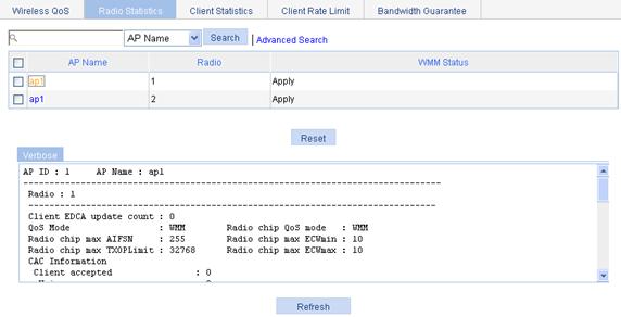
Displaying the radio statistics
1. Select QoS > Wireless QoS from the navigation tree.
2. Click the Radio Statistics tab to enter the page displaying radio statistics.
3. Click an AP to see its details.
Figure 40 Displaying the radio statistics
|
Field |
Description |
|
AP ID |
AP ID. |
|
AP Name |
AP name. |
|
Radio |
Radio ID. |
|
Client EDCA update count |
Number of client EDCA parameter updates. |
|
QoS mode |
QoS mode: · WMM—Indicates that the client is a QoS client. · None—Indicates that the client is a non-QoS client. |
|
Radio chip QoS mode |
Radio chip's support for the QoS mode. |
|
Radio chip max AIFSN |
Maximum AIFSN allowed by the radio chip. |
|
Radio chip max ECWmin |
Maximum ECWmin allowed by the radio chip. |
|
Radio chip max TXOPLimit |
Maximum TXOPLimit allowed by the radio chip. |
|
Radio chip max ECWmax |
Maximum ECWmax allowed by the radio chip. |
|
Client accepted |
Number of clients that have been admitted to access the radio, including the number of clients that have been admitted to access the AC-VO and the AC-VI queues. |
|
Total request mediumtime(us) |
Total requested medium time, including that of the AC-VO and the AC-VI queues. |
|
Calls rejected due to insufficient resource |
Number of requests rejected due to insufficient resources. |
|
Calls rejected due to invalid parameters |
Number of requests rejected due to invalid parameters. |
|
Calls rejected due to invalid mediumtime |
Number of requests rejected due to invalid medium time. |
|
Calls rejected due to invalid delaybound |
Number of requests rejected due to invalid delay bound. |
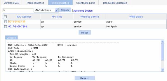
Displaying the client statistics
1. Select QoS > Wireless QoS from the navigation tree.
2. Click the Client Statistics tab to enter the page displaying client statistics.
3. Click a client name to see its details.
Figure 41 Displaying the client statistics
|
Field |
Description |
|
MAC address |
MAC address of the client. |
|
SSID |
Service set ID (SSID) |
|
QoS Mode |
QoS mode: · WMM—Indicates that QoS mode is enabled. · None—Indicates that QoS mode is not enabled. |
|
Max SP length |
Maximum service period. |
|
AC |
Access category. |
|
State |
APSD attribute of an access category: · T—The access category is trigger-enabled. · D—The access category is delivery-enabled. · T | D—The access category is both trigger-enabled and delivery-enabled. · L—The access category is of legacy attributes. |
|
Assoc State |
APSD attribute of the four access categories when a client accesses the AP. |
|
Uplink CAC packets |
Number of uplink CAC packets. |
|
Uplink CAC bytes |
Number of uplink CAC bytes. |
|
Downlink CAC packets |
Number of downlink CAC packets. |
|
Downlink CAC bytes |
Number of downlink CAC bytes. |
|
Downgrade packets |
Number of downgraded packets. |
|
Downgrade bytes |
Number of downgraded bytes. |
|
Discard packets |
Number of dropped packets. |
|
Discard bytes |
Number of dropped bytes. |
Setting rate limiting
The WLAN provides limited bandwidth for each AP. Because the bandwidth is shared by wireless clients attached to the AP, aggressive use of bandwidth by a client will affect other clients. To ensure fair use of bandwidth, rate limit traffic of clients in either of the following approaches:
· Configure the total bandwidth shared by all clients in the same BSS. This is called "dynamic mode". The rate limit of a client is the configured total rate/the number of online clients. For example, if the configure total rate is 10 Mbps and five clients are online, the rate of each client is 2 Mbps.
· Configure the maximum bandwidth that can be used by each client in the BSS. This is called "static mode". For example, if the configured rate is 1 Mbps, the rate limit of each user online is 1 Mbps. When the set rate limit multiplied by the number of access clients exceeds the available bandwidth provided by the AP, no clients can get the guaranteed bandwidth.
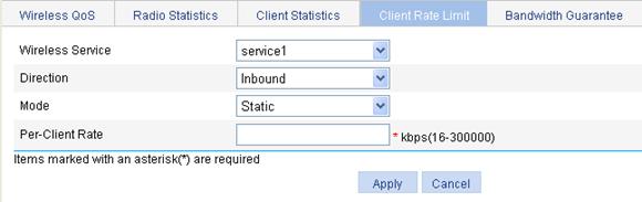
Setting wireless service-based client rate limiting
You can configure the access controller to limit client rates for a service within a BSS.
To set wireless service-based client rate limiting:
1. Select QoS > Wireless QoS from the navigation tree on the left.
2. Click the Client Rate Limit tab.
3. Click Add in the Service-Based Configuration area to enter the page for setting wireless service-based client rate limits, as shown in Figure 42.
Figure 42 Setting wireless service-based client rate limiting
4. Configure service-based client rate limiting, as described in Table 26.
5. Click Apply.
|
Item |
Description |
|
Wireless Service |
Select an existing wireless service. |
|
Direction |
Set the traffic direction: · Inbound—Traffic from client to AP. · Outbound—Traffic from AP to client. · Both—Both inbound and outbound traffic. |
|
Mode |
Set a rate limiting mode: · Static—Limits the rate of each client to a fixed value. · Dynamic—Limits the total rate of all clients to a fixed value. |
|
Rate |
Set the rate of the clients. · If you select the static mode, Per-Client Rate is displayed, and the rate is the rate of each client. · If you select the dynamic mode, Total Rate is displayed, and the rate is the total rate of all clients. |
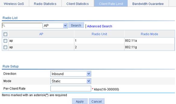
Setting radio-based client rate limiting
You can configure the access controller to limit client rates for a radio.
To set radio-based client rate limiting:
1. Select QoS > Wireless QoS from the navigation tree on the left.
2. Click the Client Rate Limit tab.
3. Click Add in the Radio-Based Configuration area to enter the page for setting radio-based client rate limiting, as shown in Figure 42.
Figure 43 Setting radio-based client rate limiting
4. Configure radio-based client rate limiting, as described in Table 27.
5. Click Apply.
|
Item |
Description |
|
Radio List |
List of radios available. You can create the rate limiting rules for one or multiple radios. |
|
Direction |
Traffic direction: · Inbound—Traffic from clients to the AP. · Outbound—Traffic from the AP to clients. · Both—Includes inbound traffic (traffic from clients to the AP) and outbound traffic (traffic from the AP to clients) |
|
Mode |
Rate limiting mode: · Static—Limits the rate of each client to a fixed value. · Dynamic—Limits the total rate of all clients to a fixed value. |
|
Rate |
Set the rate of the clients: · If you select the static mode, Per-Client Rate is displayed, and the rate is the rate of each client. · If you select the dynamic mode, Total Rate is displayed, and the rate is the total rate of all clients. |
Configuring the bandwidth guarantee function
When traffic is heavy, a BSS without any rate limitation may aggressively occupy the available bandwidth for other BSSs. If you limit the rate of the BSS, it cannot use the idle bandwidth of other BSSs.
To improve bandwidth use efficiency when ensuring bandwidth use fairness among wireless services, use the bandwidth guarantee function. Bandwidth guarantee makes sure all traffic from each BSS can pass through freely when the network is not congested, and each BSS can get the guaranteed bandwidth when the network is congested.
For example, suppose you guarantee SSID1, SSID2, and SSID3 25%, 25%, and 50% of the bandwidth. When the network is not congested, SSID1 can use all idle bandwidth in addition to its guaranteed bandwidth. When the network is congested, SSID1 can use at least its guaranteed bandwidth, 25% of the bandwidth.
|
|
NOTE: Bandwidth guarantees apply only to the traffic from AP to client. |
Setting the reference radio bandwidth
1. Select QoS > Wireless QoS from the navigation tree.
2. Click the Bandwidth Guarantee tab to enter the page for configuring bandwidth guarantees, as shown in Figure 44.
Figure 44 Setting the reference radio bandwidth
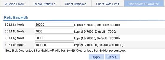
3. Set the reference radio bandwidth, as described in Table 28.
4. Click Apply.
|
|
NOTE: The reference radio bandwidth modification does not immediately take effect on the radios with the bandwidth guarantee function enabled. To make the modification take effect, disable and then enable the radios. |
|
Item |
Description |
|
802.11a Mode |
Set the reference radio bandwidth.
Set the reference radio bandwidth slightly lower than the maximum available bandwidth.. |
|
802.11b Mode |
|
|
802.11g Mode |
|
|
802.11n Mode |
Setting guaranteed bandwidth percents
1. Select a radio from the radio list, and click the ![]() icon
for the radio in the Operation column to enter the page for setting guaranteed bandwidth, as shown
in Figure 45.
icon
for the radio in the Operation column to enter the page for setting guaranteed bandwidth, as shown
in Figure 45.
Figure 45 Setting guaranteed bandwidth
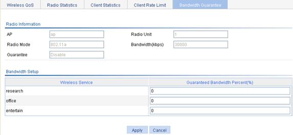
2. Set the guaranteed bandwidth, as described in Table 29.
3. Click Apply.
|
Item |
Description |
|
Guaranteed Bandwidth Percent (%) |
Allocate guaranteed bandwidth as a percentage of the radio bandwidth to each wireless service. The total guaranteed bandwidth cannot exceed 100% of the ratio bandwidth. |
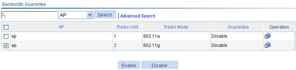
Enabling bandwidth guaranteeing
To validate the bandwidth guarantee settings for a radio unit, enable its bandwidth guarantee function.
To enable the bandwidth guarantee function:
1. Select QoS > Wireless QoS from the navigation tree on the left.
2. Click the Bandwidth Guarantee tab to enter the page for configuring bandwidth guarantee.
3. Select the AP and the corresponding radio mode for which you want to enable bandwidth guarantee on the list under the Bandwidth Guarantee title bar.
4. Click Enable.
Figure 46 Enabling the bandwidth guarantee function
Displaying guaranteed bandwidth settings
1. Select QoS > Wireless QoS from the navigation tree on the left.
2. Click Bandwidth Guarantee.
3. Click the specified radio unit of the AP on the list under the Bandwidth Guarantee title bar to view the wireless services bound to the radio unit and the guaranteed bandwidth setting for each wireless service.
Figure 47 Displaying guaranteed bandwidth settings
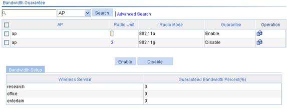
CAC service configuration example
Network requirements
As shown in Figure 48, a WMM-enabled AP accesses the Ethernet.
Enable CAC for AC-VO and AC-VI on the AP. To guarantee high priority clients (AC-VO and AC-VI clients) sufficient bandwidth, use the user number-based admission policy to limit the number of access users to 10.
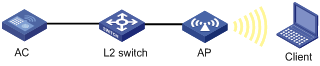
Configuring the wireless service
1. Configure the AP, and establish a connection between the AC and the AP.
For related configurations, see "Configuring access services." Follow the steps in the related configuration example to establish a connection between the AC and the AP.
Configuring wireless QoS
1. Select QoS > Wireless QoS from the navigation tree.
By default, the Wireless QoS tab is displayed.
2. Make sure WMM is enabled.
Figure 49 Wireless QoS configuration page (1)
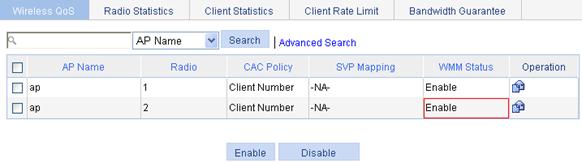
3.
As shown in Figure 49,
select the AP to be configured on the list and click the ![]() icon for
the AP in the Operation column to enter the page for configuring wireless QoS.
icon for
the AP in the Operation column to enter the page for configuring wireless QoS.
4.
On the Client EDCA list, select the priority
type (AC_VO, for example) to be modified, and click the ![]() icon
for the priority type in the Operation column to enter the page for setting client EDCA parameters.
icon
for the priority type in the Operation column to enter the page for setting client EDCA parameters.
5. Select Enable from the CAC list.
6. Click Apply.
Figure 50 Enabling CAC
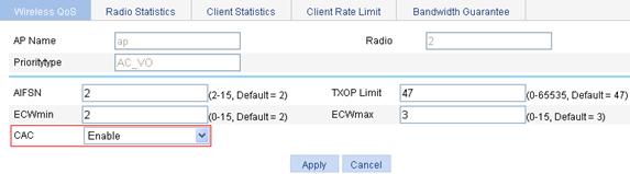
7. Enable CAC for AC_VI in the same way. (Details not shown.)
8. Select QoS > Wireless QoS from the navigation tree.
By default, the Wireless QoS tab is displayed.
9.
Click the ![]() icon
in the Operation column for the desired AP to enter the page for configuring
wireless QoS.
icon
in the Operation column for the desired AP to enter the page for configuring
wireless QoS.
10. Select the Client Number option, and then enter 10.
11. Click Apply.
Figure 51 Setting CAC client number
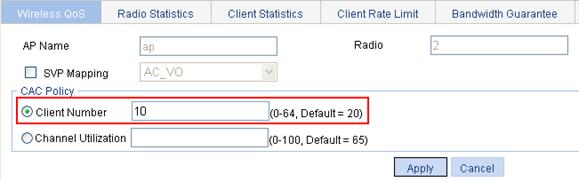
Verifying the configuration
If the number of existing clients in the high-priority access categories plus the number of clients requesting for high-priority access categories is smaller than or equal to the user-defined maximum number of users allowed in high-priority access categories, which is 10 in this example, the request is allowed. Otherwise, the request is rejected.
Wireless service-based static rate limiting configuration example
Network requirements
As shown in Figure 52, two wireless clients access the WLAN through a SSID named service1.
Limit the maximum bandwidth per wireless client to 128 kbps for traffic from the wireless clients to the AP.

Configuring the wireless service
For the configuration procedure, see "Configuring access services."
Configuring static rate limiting
1. Select QoS > Wireless QoS from the navigation tree.
2. Click Client Rate Limit.
3. Click Add in the Service-Based Configuration area to enter the page for configuring wireless service-based rate limit settings for clients, as shown in Figure 53.
4. Configure static rate limiting:
a. Select service1 from the Wireless Service list.
b. Select Inbound from the Direction list.
c. Select Static from the Mode list.
d. Enter 128 in the Per-Client Rate field.
5. Click Apply.
Figure 53 Configuring static rate limiting
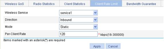
Verifying the configuration
1. Client1 and Client2 access the WLAN through the SSID named service1.
2. Check that traffic from Client1 is rate limited to around 128 kbps, so is traffic from Client2.
Wireless service-based dynamic rate limiting configuration example
Network requirements
As shown in Figure 54, wireless clients access the WLAN through a SSID named service2.
Configure all wireless clients to share 8000 kbps of bandwidth in any direction.
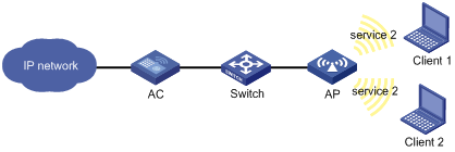
Configuring the wireless service
For the configuration procedure, see "Configuring access services."
Configuring dynamic rate limiting
1. Select QoS > Wireless QoS from the navigation tree.
2. Click Client Rate Limit.
3. Click Add in the Service-Based Configuration area to enter the page for configuring wireless service-based rate limit settings for clients, as shown in Figure 55.
4. Configure dynamic rate limiting:
a. Select service2 from the Wireless Service list.
b. Select Both from the Direction list.
c. Select Dynamic from the Mode list.
d. Enter 8000 in the Total Rate field.
5. Click Apply.
Figure 55 Configuring dynamic rate limiting
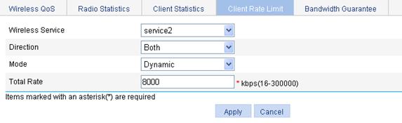
Verifying the configuration
Check that:
1. When only Client1 accesses the WLAN through SSID service2, its traffic can pass through at a rate as high as 8000 kbps.
2. When both Client1 and Client2 access the WLAN through SSID service2, their traffic flows can each pass through at a rate as high as 4000 kbps.
Bandwidth guarantee configuration example
Network requirements
As shown in Figure 56, three wireless clients use wireless services research, office, and entertain to access the wireless network.
To make sure the enterprise network works properly, guarantee the office service 20% of the bandwidth, the research service 80%, and the entertain service none.
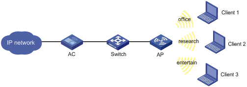
Configuring the wireless services
For the configuration procedure, see "Configuring access services." Follow the related configuration example to configure the wireless services.
Configuring bandwidth guaranteeing
1. Select QoS > Wireless QoS from the navigation tree.
2. Click Bandwidth Guarantee to enter the page for configuring bandwidth guarantee, as shown in Figure 57.
3. Use the default reference radio bandwidth for 802.11a.
4. Click Apply.
Figure 57 Setting the reference radio bandwidth
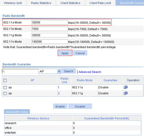
5. Click the ![]() icon in
the Operation column for 802.11a to enter the page for setting guaranteed
bandwidth, as shown in Figure
58.
icon in
the Operation column for 802.11a to enter the page for setting guaranteed
bandwidth, as shown in Figure
58.
6. Set the guaranteed bandwidth:
a. Set the guaranteed bandwidth percent to 80 for wireless service research.
b. Set the guaranteed bandwidth percent to 20 for wireless service office.
c. Set the guaranteed bandwidth percent to 0 for wireless service entertain.
7. Click Apply.
After you apply the guaranteed bandwidth settings, the page for enabling bandwidth guarantee appears, as shown in Figure 59.
Figure 58 Setting guaranteed bandwidth
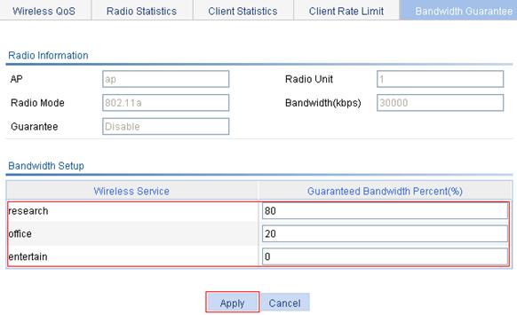
8. Select the option specific to 802.11a.
9. Click Enable.
Figure 59 Enabling bandwidth guarantee
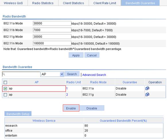
Verifying the configuration
· Send traffic from the AP to the three wireless clients at a rate lower than 30000 kbps. The rate of traffic from the AP to the three wireless clients is not limited.
· Send traffic at a rate higher than 6000 kbps from the AP to Client 1 and at a rate higher than 24000 kbps from the AP to Client 2. The total rate of traffic rate from the AP to the two wireless clients exceeds 30000 kbps. Because you have enabled bandwidth guarantee for wireless services research and office, the AP forwards traffic to Client 1 and Client 2 respectively at 6000 kbps and 24000 kbps, and limits the traffic to Client 3.
|
|
NOTE: · Guaranteed bandwidth in kbps = reference radio bandwidth × guaranteed bandwidth percent. · Set the reference radio bandwidth slightly lower than the available maximum bandwidth. · The guaranteed bandwidth configuration applies to only the traffic from the AP to clients. |
