- Table of Contents
-
- H3C WX Series Access Controllers Web-Based Configuration Guide(R3308 R2308)-6W107
- 00-Preface
- 01-About the WX Series Access Controllers Web Configuration Guide
- 02-Quick Start
- 03-Web Overview
- 04-Summary
- 05-Device
- 06-Network
- 07-AP Configuration
- 08-Wireless Service
- 09-WLAN Roaming Configuration
- 10-Radio Configuration
- 11-Authentication
- 12-Security
- 13-QoS configuration
- 14-Advanced Settings
- 15-Stateful Failover Configuration
- Related Documents
-
| Title | Size | Download |
|---|---|---|
| 10-Radio Configuration | 544.13 KB |
Contents
Configuring data transmit rates
Configuring 802.11a/802.11b/802.11g rates
Manual channel adjustment configuration example
Automatic power adjustment configuration example
Radio group configuration example
Radio overview
Radio frequency (RF) refers to electrical signals that can be transferred over the space to a long distance. 802.11b/g in the IEEE 802.11 standards operates at the 2.4 GHz band, 802.11a operates at the 5 GHz band, and 802.11n operates at both the 2.4 GHz and 5 GHz bands. Radio frequency is allocated in bands, each of which corresponds to a range of frequencies.
WLAN RRM overview
Radio signals are susceptible to surrounding interference. The causes of radio signal attenuation in different directions are very complex, so you need to make careful plans before deploying a WLAN network. After WLAN deployment, the running parameters must still to be adjusted because the radio environment is always varying due to interference from mobile obstacles, micro-wave ovens and so on. To adapt to environment changes, radio resources such as working channels and transmit power should be dynamically adjusted. Such adjustments are complex and require experienced personnel to implement regularly, which brings high maintenance costs.
WLAN radio resource management (RRM) is a scalable radio resource management solution. Through information collection (APs collect radio environment information in real time), information analysis (The AC analyzes the collected information), decision-making (The AC makes radio resource adjustment configuration according to analysis results), and implementation (APs implement the configuration made by the AC for radio resource optimization), WLAN RRM delivers a real-time, intelligent, integrated radio resource management solution, which enables a WLAN network to quickly adapt to radio environment changes and ensures the optimal communication quality.
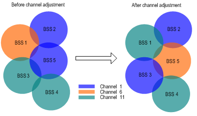
Dynamic frequency selection
A WLAN has limited working channels. Channel overlapping can easily occur. In addition, other radio sources such as radar and micro-wave ovens may interfere with the operation of APs. Dynamic frequency selection (DFS) can solve these problems.
With DFS, the AC selects an optimal channel for each AP in real time to avoid co-channel interference and interference from other radio sources.
The following conditions determine DFS:
· Error code rate—physical layer error code and CRC errors.
· Interference—influence of 802.11 and non-802.11 wireless signals on wireless services.
· Retransmission—APs retransmit data if they do not receive ACK messages from the AC.
· Radar signal detected on a working channel—the AC immediately notifies the AP to change its working channel.
If the first three conditions are met, the AC calculates the channel quality. The AP does not use the new channel until the channel quality difference between the new and old channels exceeds the tolerance level.
Figure 1 Dynamic channel adjustment
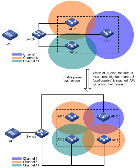
Transmit power control
Traditionally, an AP uses the maximum power to cover an area as large as possible. This method, however, affects the operation of surrounding wireless devices. Transmit power control (TPC) is used to select a proper transmission power for each AP to satisfy both coverage and usage requirements.
Whether the transmission power of an AP is increased or decreased is determined by these factors: the maximum number of neighbors (detected neighbors that are managed by the same AC), the neighbor AP that performs power detection, and the power adjustment threshold.
|
|
NOTE: You cannot configure the neighbor AP that performs power detection and the power adjustment threshold on the web interface. |
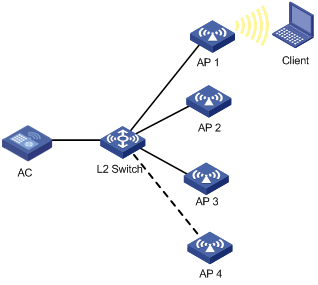
As shown in Figure 2, APs 1, 2 and 3 cover an area. When AP 4 joins, the default maximum neighbor number 3 (configurable) is reached. Then, the APs perform power adjustment. You can find from the figure that they all reduce their transmission power.
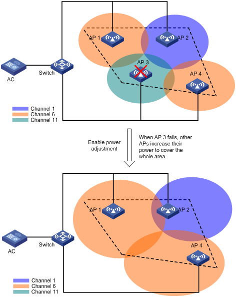
As shown in Figure 3, when AP 3 fails or goes offline, the other APs increase their transmission power to cover the signal blackhole.
Radio setup
Configuring radio parameters
1. Select Radio > Radio from the navigation tree.
2.
Click the ![]() icon
of the desired AP to enter the
page for AP radio setup.
icon
of the desired AP to enter the
page for AP radio setup.
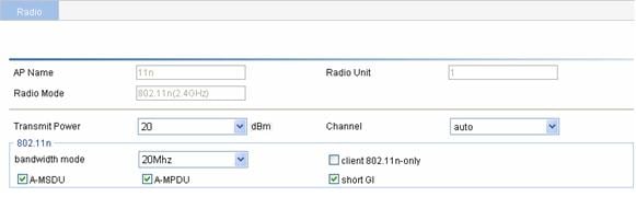
3. Configure the radio as described in Table 1.
|
Item |
Description |
|
AP Name |
Display the selected AP. |
|
Radio Unit |
Display the selected AP's radios. |
|
Radio Mode |
Display the selected AP's radio mode. |
|
Transmit Power |
Maximum radio transmission power, which varies with country codes, channels, AP models, radio modes and antenna types. If you adopt the 802.11n mode, the maximum transmit power of the radio also depends on the bandwidth mode. |
|
Channel |
Specify the working channel of the radio, which varies with radio types and country codes. The working channel list varies with device models. auto—The working channel is automatically selected. If you select this mode, the AP checks the channel quality in the WLAN network, and selects the channel of the best quality as its working channel. If you modify the working channel configuration, the transmit power is automatically adjusted. |
|
802.11n |
The option is available only when the AP supports 802.11n. |
|
bandwidth mode |
802.11n can bond two adjacent 20-MHz channels together to form a 40-MHz channel. During data forwarding, the two 20-MHz channels can work separately with one acting as the primary channel and the other acting as the secondary channel or work together as a 40-MHz channel. This provides a simple way of doubling the data rate. By default, the channel bandwidth of the 802.11n radio (5 GHz) is 40 MHz, and that of the 802.11n radio (2.4GHz) is 20 MHz.
· If the channel bandwidth of the radio is set to 40 MHz, a 40 MHz channel is used as the working channel. If no 40 MHz channel is available, a 20 MHz channel is used. For the specifications, see IEEE P802.11n D2.00. · If you modify the bandwidth mode configuration, the transmit power is automatically adjusted. |
|
client dot11n-only |
If you select the client dot11n-only option, non-802.11n clients are prohibited from access. If you want to provide access for all 802.11a/b/g clients, you must disable this function. |
|
A-MSDU |
Select the A-MSDU option to enable A-MSDU. Multiple MAC Service Data Units (MSDU) can be aggregated into a single A-MSDU. This reduces the MAC header overhead and thus improves MAC layer forwarding efficiency. At present, only A-MSDUs can be received.
When 802.11n radios are used in a mesh WLAN, ensure that they have the same A-MSDU configuration. |
|
A-MPDU |
Select the A-MPDU option to enable A-MPDU. 802.11n introduces the A-MPDU frame format. By using only one PHY header, each A-MPDU can accommodate multiple Message Protocol Data Units (MPDUs) which have their PHY headers removed. This reduces the overhead in transmission and the number of ACK frames to be used, and thus improves network throughput.
When 802.11n radios are used in a mesh WLAN, ensure that they have the same A-MSDU configuration. |
|
short GI |
Select short GI to enable short GI. The 802.11a/g GI is 800ns. You can configure a short GI, 400 ns for 802.11n. The short GI increases the throughput by 10 percent. |
4. Expand Advanced Setup.
Figure 5 Radio setup (advanced setup)
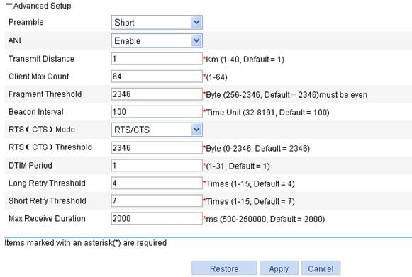
5. Configure the radio as described in Table 2.
6. Click Apply.
|
Item |
Description |
|
Preamble |
Preamble is a pattern of bits at the beginning of a frame so that the receiver can sync up and be ready for the real data. · Short preamble—A short preamble improves network performance. Therefore, this option is always selected. · Long preamble—A long preamble ensures compatibility between access point and some legacy client devices. Therefore, you can select this option to make legacy client devices support short preamble. 802.11a/802.11n (5 GHz) do not support this configuration. |
|
Transmit Distance |
Maximum coverage of a radio. |
|
ANI |
Adaptive Noise Immunity (ANI). After the ANI function is enabled, the device automatically adjusts the noise immunity level according to the surrounding signal environment to eliminate RF interference. · Enable—Enable ANI. · Disable—Disable ANI. |
|
Client Max Count |
Maximum number of clients that can be associated with one radio. |
|
Fragment Threshold |
Specify the maximum length of frames that can be transmitted without fragmentation. When the length of a frame exceeds the specified fragment threshold value, it is fragmented. · In a wireless network where error rate is high, you can decrease the fragment threshold by a rational value. In this way, when a fragment of a frame is not received, only this fragment rather than the whole frame needs to be retransmitted, and thus the throughput of the wireless network is improved. · In a wireless network where no collision occurs, you can increase the fragment threshold by a rational value to decrease acknowledgement packets and thus increase network throughput. |
|
Beacon Interval |
Interval for sending beacon frames. Beacon frames are transmitted at a regular interval to allow mobile clients to join the network. Beacon frames are used for a client to identify nearby APs or network control devices. |
|
RTS (CTS) |
There are two data collision avoidance mechanisms, RTS/CTS and CTS-to-self. · RTS/CTS—In this mode, an AP sends an RTS packet before sending data to a client. After receiving the RTS packet, all the devices within the coverage of the AP will not send data within the specified time. Upon receiving the RTS packet, the client sends a CTS packet, ensuring that all the devices within the coverage of the client will not send data within the specified time. The RTS/CTS mechanism requires two frames to implement data collision avoidance, and thus has a higher cost. · CTS-to-Self—In this mode, an AP uses its IP address to send a CTS packet before sending data to a client, ensuring that all the devices within the coverage of the AP will not send data within the specified time. The CTS-to-Self mechanism uses only one frame to avoid data collision. However, if another device is in the coverage of the client, but not in the coverage of the AP, data collision still may occur. Compared with RTS/CTS, CTS-to-Self reduces the number of control frames. However, data collisions still occur when some clients are hidden and thus cannot receive the CTS frames sent by the AP. Therefore, the RTS/CTS mechanism can solve the data collision problem in a larger coverage than RTS/CTS. |
|
RTS (CTS) Threshold |
If a frame is larger than the RTS (CTS) threshold, the data collision avoidance mechanism is used. A smaller RTS/CTS threshold causes RTS/CTS packets to be sent more often, thus consuming more bandwidth. However, the more often RTS/CTS packets are sent, the quicker the system can recover from collisions. In a high-density WLAN, you can decrease the RTS threshold to reduce collisions in the network.
The data collision avoidance mechanism occupies bandwidth. Therefore, this mechanism applies only to data frames larger than the RTS/CTS threshold. |
|
DTIM Period |
Number of beacon intervals between delivery traffic indication message (DTIM) transmissions. The AP sends buffered broadcast/multicast frames when the DTIM counter reaches 0. |
|
Long Retry Threshold |
Number of retransmission attempts for unicast frames larger than the RTS/CTS threshold. |
|
Short Retry Threshold |
Number of retransmission attempts for unicast frames smaller than the RTS/CTS threshold if no acknowledgment is received for it. |
|
Max Receive Duration |
Interval for which a frame received by an AP can stay in the buffer memory. |
Enabling a radio
1. Select Radio > Radio from the navigation tree to enter the radio setup page.
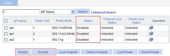
2. Select the box of the target radio.
3. Click Enable.
Locking the channel
1. Select Radio > Radio from the navigation tree to enter the page as shown in Figure 7.
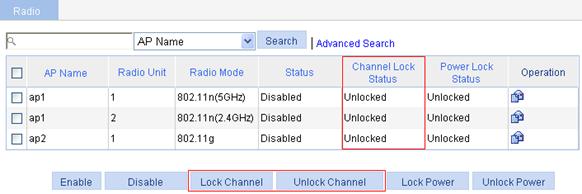
2. Select the box of the target radio.
3. Click Lock Channel.
¡ Channel locking takes effect only when the AC adopts the auto mode. For more information about automatic channel adjustment, see "Configuring radio parameters."
¡ If you enable channel locking and then enable the radio, the AC automatically selects an optimal channel, and then locks the channel.
¡ When the AC detects any radar signals, it immediately selects another channel even if the current channel is locked, and then locks the new channel.
¡ If you lock the current channel first, and then enable channel adjustment, channel adjustment does not work because the current channel is locked. Therefore, before enabling channel adjustment, make sure that the current channel is not locked. If you enable channel adjustment and then lock the current channel, the last selected channel is locked. For information about channel adjustment, see "Dynamic frequency selection." For more information about channel adjustment configuration, see "Parameter setting."
Locking the power
1. Select Radio > Radio from the navigation tree to enter the page as shown in Figure 8.
Figure 8 Locking the current power
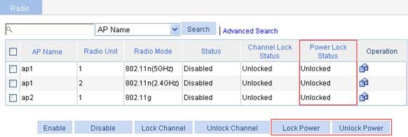
2. Select the box of the target radio.
3. Click Lock Power.
¡ For transmission power configuration, see "Configuring radio parameters."
¡ If you lock the current power first, and then enable power adjustment, power adjustment does not work because the power is locked. Therefore, before enabling power adjustment, make sure that the current power is not locked. If you enable power adjustment, and then lock the current power, the last selected power is locked. For information about power adjustment, see "Transmit power control." For how to configure power adjustment, see "Parameter setting."
Configuring data transmit rates
Configuring 802.11a/802.11b/802.11g rates
1. Select Radio > Rate from the navigation tree to enter the rate setting page.
Figure 9 Setting 802.11a/802.11b/802.11g rates
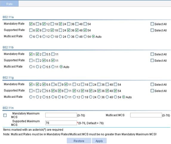
2. Configure 802.11a/802.11b/802.11g rates as described in Table 3.
3. Click Apply.
|
Item |
Description |
|
802.11a |
Configure rates (in Mbps) for 802.11a. By default: · Mandatory rates are 6, 12, and 24. · Supported rates are 9, 18, 36, 48, and 54. · Multicast rate: Automatically selected from the mandatory rates. The transmission rate of multicasts in a BSS is selected from the mandatory rates supported by all the clients. |
|
802.11b |
Configure rates (in Mbps) for 802.11b. By default: · Mandatory rates are 1 and 2. · Supported rates are 5.5 and 11. · Multicast rate: Automatically selected from the mandatory rates. The transmission rate of multicasts in a BSS is selected from the mandatory rates supported by all the clients. |
|
802.11g |
Configure rates (in Mbps) for 802.11g. By default: · Mandatory rates are 1, 2, 5.5, and 11. · Supported rates are 6, 9, 12, 18, 24, 36, 48, and 54. · Multicast rate: Automatically selected from the mandatory rates. The transmission rate of multicasts in a BSS is selected from the mandatory rates supported by all the clients. |
Configuring 802.11n MCS
Introduction to MCS
Configuration of mandatory and supported 802.11n rates is achieved by specifying the maximum Modulation and Coding Scheme (MCS) index. The MCS data rate table shows relations between data rates, MCS indexes, and parameters that affect data rates. Sample MCS data rate tables for 20 MHz and 40 MHz are shown in Table 4 and Table 5 respectively. For the entire table, see IEEE P802.11n D2.00.
Table 4 and Table 5 indicate that MCS 0 through 7 are for one single spatial stream, and when the MCS is 7, the data rate is the highest. MCS 8 through 15 are for two spatial streams, and when the MCS is 15, the data rate is the highest.
Table 4 MCS index table (20 MHz)
|
MCS index |
Number of spatial streams |
Modulation |
Data rate (Mbps) |
|
|
800ns GI |
400ns GI |
|||
|
0 |
1 |
BPSK |
6.5 |
7.2 |
|
1 |
1 |
QPSK |
13.0 |
14.4 |
|
2 |
1 |
QPSK |
19.5 |
21.7 |
|
3 |
1 |
16-QAM |
26.0 |
28.9 |
|
4 |
1 |
16-QAM |
39.0 |
43.3 |
|
5 |
1 |
64-QAM |
52.0 |
57.8 |
|
6 |
1 |
64-QAM |
58.5 |
65.0 |
|
7 |
1 |
64-QAM |
65.0 |
72.2 |
|
8 |
2 |
BPSK |
13.0 |
14.4 |
|
9 |
2 |
QPSK |
26.0 |
28.9 |
|
10 |
2 |
QPSK |
39.0 |
43.3 |
|
11 |
2 |
16-QAM |
52.0 |
57.8 |
|
12 |
2 |
16-QAM |
78.0 |
86.7 |
|
13 |
2 |
64-QAM |
104.0 |
115.6 |
|
14 |
2 |
64-QAM |
117.0 |
130.0 |
|
15 |
2 |
64-QAM |
130.0 |
144.4 |
Table 5 MCS index table (40 MHz)
|
MCS index |
Number of spatial streams |
Modulation |
Data rate (Mbps) |
|
|
800ns GI |
400ns GI |
|||
|
0 |
1 |
BPSK |
13.5 |
15.0 |
|
1 |
1 |
QPSK |
27.0 |
30.0 |
|
2 |
1 |
QPSK |
40.5 |
45.0 |
|
3 |
1 |
16-QAM |
54.0 |
60.0 |
|
4 |
1 |
16-QAM |
81.0 |
90.0 |
|
5 |
1 |
64-QAM |
108.0 |
120.0 |
|
6 |
1 |
64-QAM |
121.5 |
135.0 |
|
7 |
1 |
64-QAM |
135.0 |
150.0 |
|
8 |
2 |
BPSK |
27.0 |
30.0 |
|
9 |
2 |
QPSK |
54.0 |
60.0 |
|
10 |
2 |
QPSK |
81.0 |
90.0 |
|
11 |
2 |
16-QAM |
108.0 |
120.0 |
|
12 |
2 |
16-QAM |
162.0 |
180.0 |
|
13 |
2 |
64-QAM |
216.0 |
240.0 |
|
14 |
2 |
64-QAM |
243.0 |
270.0 |
|
15 |
2 |
64-QAM |
270.0 |
300.0 |
For example, if you specify the maximum MCS index as 5 for mandatory rates, rates corresponding to MCS indexes 0 through 5 are configured as 802.11n mandatory rates.
· Mandatory rates must be supported by the AP and the clients that want to associate with the AP.
· Supported rates allow some clients that support both mandatory and supported rates to choose higher rates when communicating with the AP.
· Multicast MCS: Specifies 802.11n multicast data rates.
Configuring 802.11n rates
1. Select Radio > Rate from the navigation tree to enter the rate setting page.
Figure 10 Setting 802.11n rate
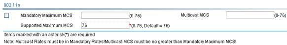
2. Configure the 802.11n rate as described in Table 6.
3. Click Apply.
|
Item |
Description |
|
Mandatory Maximum MCS |
Set the maximum MCS index for 802.11n mandatory rates.
If you select the client dot11n-only option, you must configure the mandatory maximum MCS. |
|
Multicast MCS |
Set the multicast MCS for 802.11n. The multicast MCS is adopted only when all the clients use 802.11n. If a non 802.11n client exists, multicast traffic is transmitted at a mandatory MCS data rate.
· If you configure a multicast MCS index greater than the maximum MCS index supported by the radio, the maximum MCS index is adopted. · When the multicast MCS takes effect, the corresponding data rates defined for 20 MHz are adopted no matter whether the 802.11n radio operates in 40 MHz mode or in 20 MHz mode. |
|
Supported Maximum MCS |
Set the maximum MCS index for 802.11n supported rates. |
|
|
NOTE: When 802.11n radios are used in a mesh WLAN, make sure that they have the same MCS configuration. |
Configuring channel scanning
|
|
NOTE: For more information about active passive scanning, see "WLAN service configuration." |
1. Select Radio > Scan from the navigation tree to enter the page for setting channel scanning.
Figure 11 Setting channel scanning
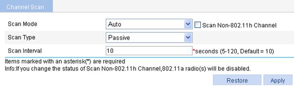
2. Configure channel scanning as described in Table 7.
3. Click Apply.
|
Item |
Description |
|
Scan Mode |
Set the scan mode. · Auto—Legal channels with the scanning mode under country code are scanned. · All—All the channels of the radio band are scanned. |
|
Scan Non-802.11h Channel |
Some of 802.11h channels, also called radar channels, overlap some 802.11a channels. If the device operates on an overlapping channel, its service quality may be affected. With this function enabled, the device selects a working channel from non-802.11h channels belonging to the configured country code to avoid channel collision. Selecting the Scan Non-802.11h Channel option enables the function of scanning non-802.11h channels. By default, the scan mode is auto, that is, all channels of the country code being set are scanned. |
|
Scan Type |
Set the scan type. · Active—The active scanning mode requires a client to send a probe request. This scanning mode enables a client to discover APs more easily. · Passive—Passive scanning is used by a client when it wants to save battery power. Typically, VoIP clients adopt the passive scanning mode. For an AP that has the monitoring function: · Active—The AP simulates a client to send probe requests during the scanning process. · Passive—The AP does not send probe requests during the scanning process. If you set active scanning for the AP, it is more likely to discover devices in the WLAN. |
|
Scan Interval |
Set the scan report interval. · A longer scan interval enables an AP to discover more devices in the WLAN. · A shorter scan interval enables an AP to send scanning reports to an AC more frequently. If an AP has the monitoring function, the scan report interval will affect whether the scanning results can be processed in time and the frequency of message exchanges. Therefore, you need to set the interval properly according to the actual network conditions. |
Configuring calibration
Parameter setting
1. Select Radio > Calibration from the navigation tree.
2. Click the Parameters tab.
Figure 12 Setting channel calibration
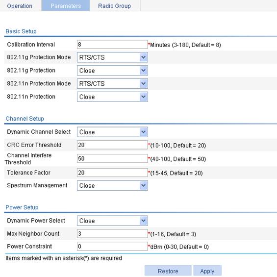
3. Configure channel calibration as described in Table 8.
4. Click Apply.
|
|
NOTE: Channel switching results in temporary service interruption, so use the dynamic channel adjustment function with caution. |
|
Item |
Description |
|
|
Basic Setup |
Calibration Interval |
Channel and power calibration interval. A calibration interval takes effect on both the mesh network channel calibration and channel and power calibration of wireless services. |
|
802.11g Protection Mode |
· RTS/CTS—Use RTS/CTS mode to implement 802.11g protection. Before sending data to a client, an AP sends an RTS packet to the client, ensuring that all the devices within the coverage of the AP do not send data in the specified time after receiving the RTS packet. Upon receiving the RTS packet, the client will send a CTS packet again, ensuring that all the devices within the coverage of the client do not send data in the specified time. · CTS-to-Self—Uses CTS-to-Self mode to implement 802.11g protection. When an AP sends packets to a client, it uses its IP address to send a CTS packet to inform the client that it will send a packet, ensuring that all the devices within the coverage of the AP do not send data in the specified time. |
|
|
802.11g Protection |
802.11b devices and 802.11g devices use different modulation modes, so 802.11g protection needs to be enabled for a 802.11g device to send RTS/CTS or CTS-to-self packets to 802.11b devices, which will defer access to the medium. An AP running 802.11g uses the 802.11g protection function in the following two cases: · An 802.11b client is associated with it. · It detects APs or clients running 802.11b on the same channel. · Enable—Enable 802.11g protection. · Close—Disable 802.11g protection.
· Enabling 802.11g protection reduces network performance. · Enabling 802.11g protection applies to the second case only, because 802.11g protection is always enabled for the first case. |
|
|
802.11n Protection Mode |
Both RTS/CTS and CTS-to-Self modes can be adopted. The implementation of the two modes is the same as 802.11g. |
|
|
802.11n Protection |
· Enable—Enables 802.11n protection. When non 802.11n wireless devices or non 802.11n clients exist within the coverage of the AP, you need to enable 802.11n protection. · Close—Disables 802.11n protection. |
|
|
Channel Setup |
Note the following guidelines when configuring channel adjustment: · Before configuring channel adjustment, make sure that the AC adopts the auto channel adjustment mode (for more information, see "Configuring radio parameters."). Otherwise, channel adjustment does not work. · If you lock the channel first, and then enable channel adjustment (by selecting Dynamic Channel Select), channel adjustment does not work because the channel is locked. Before enabling channel adjustment, make sure that the channel is not locked. · If you enable channel adjustment and then lock the channel, the last selected channel is locked. For how to lock the channel, see "Locking the channel." |
|
|
Dynamic Channel Select |
· Close—Disables the DFS function. · Auto—With auto DFS enabled, an AC performs DFS for a radio when certain trigger conditions are met on the channel, and returns the result to the AP after a calibration interval (the default calibration interval is 8 minutes, which can be set through the Calibration Interval option). After that, the AC will make DFS decisions at the calibration interval automatically. · Manual—With one-time DFS configured for a radio, an AC performs DFS for the radio when certain trigger conditions are met on the channel, and returns the result to the AP after a calibration interval. After that, if you want the AC to perform DFS for the radio, you have to make this configuration again.
If you select the manual mode, click Calibration on the Calibration page every time you perform channel calibration. |
|
|
CRC Error Threshold |
Set the CRC error threshold value, in percentage. |
|
|
Channel Interference Threshold |
Set the channel interference threshold value, in percentage. |
|
|
Tolerance Factor |
A new channel is selected when either the configured CRC error threshold or interference threshold is exceeded on the current channel. However, the new channel is not applied until the quality of the current channel is worse than that of the new channel by the tolerance threshold. |
|
|
Spectrum Management |
· Enable—Enable spectrum management. · Close—Disable spectrum management. |
|
|
Power Setup |
Note the following guidelines when configuring power adjustment: · If you lock the power first, and then enable power adjustment (by selecting Dynamic Channel Select), power adjustment does not work because the power is locked. Therefore, before enabling power adjustment, make sure that the power is not locked. · If you enable power adjustment and then lock the power, the last selected power is locked. For how to lock the power, see "Locking the power." |
|
|
Dynamic Power Select |
· Close—Disables transmit power control (TPC). · Auto—With auto TPC enabled, the AC performs TPC for an AP upon certain interference and returns the result to the AP after a calibration interval (the default calibration interval is 8 minutes, which can be set through the Calibration Interval option). After that, the AC makes TPC decisions at the calibration interval automatically. · Manual—With one-time TPC configured, an AC performs TPC for the AP upon certain interference, and returns the result to the AP after a calibration interval (the default calibration interval is 8 minutes, which can be set through the Calibration Interval option). After that, if you want the AC to perform TPC for the AP, you have to make this configuration again.
If you select the manual mode, click Calibration on the Calibration page every time you perform channel calibration. |
|
|
Max Neighbor Count |
Specify the maximum number of neighbors, which are managed by the same AC. |
|
|
Power Constraint |
Set the power constraint for all 802.11a radios. After power constraint is set, the transmission power of a client is the current transmission power minus the configured power constraint value.
Enable spectrum management before configuring the power constraint; otherwise, the configuration does not take effect. |
|
Configuring a radio group
With DFS or TPC configured for a radio, the AC calculates the channel quality or power of the radio at the calibration interval. When the result meets a trigger condition, the AC selects a new channel or power for the radio. In an environment where interference is serious, frequent channel or power adjustments may affect user access to the WLAN network. In this case, you can configure a radio group to keep the channel or power of radios in the group unchanged within a specified time. The channel and power of radios not in the radio group are adjusted normally.
After a channel or power adjustment (one-time, auto, or initial DFS or TPC), the channel or power of any radio in the radio group keeps unchanged within the specified holddown time. When the holddown time expires, the AC calculates the channel or power again. If the result meets a trigger condition, the channel or power is changed, and the new channel or power keeps unchanged within the specified holddown time. This mechanism continues.
|
|
NOTE: Before entering the Radio Group page, configure channel or power adjustment on the Parameters tab. |
1. Select Radio > Calibration from the navigation tree.
2. Click Radio Group.
3. Click Add.
The Radio Group page appears.
Figure 13 Configuring a radio group
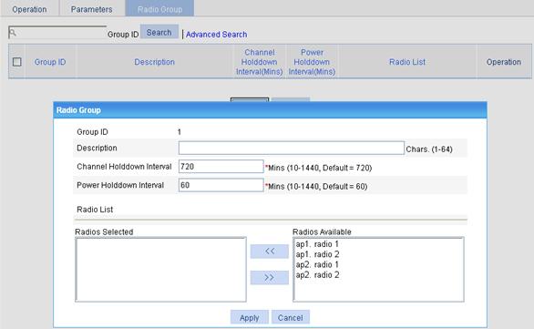
4. Configure the radio group as described in Table 9.
5. Click Apply.
|
Item |
Description |
|
Group ID |
ID of the radio group |
|
Description |
Description of the radio group By default, a radio group has no description. |
|
Channel Holddown Interval |
Specify that the current channel keeps unchanged within the specified time after a channel adjustment (manual, automatic, or initial channel selection).
The AC immediately selects another channel when it detects any radar signals on the current channel, and then resets the channel holddown timer. |
|
Power Holddown Interval |
Specify that the current power keeps unchanged within the specified time after a power adjustment (manual or automatic power adjustment). |
|
Radio List |
· Select the target radios from the Radios Available area, and then click << to add them into the Radios Selected area. · Select the radios to be removed from the Radios Selected, and the click >> to remove them from the radio group. |
Calibration operations
|
|
NOTE: If RRM is not enabled, or the radio to be displayed works on a fixed channel, you can only view the work channel and the power of the radio on the Operations tab in the Radio > Calibration page. Other information such as interference observed and the number of neighbors is displayed when RRM is enabled, that is, dynamic power selection or automatic dynamic frequency selection is enabled. For the configuration of RRM parameters, see "Parameter setting." |
Displaying channel status
1. Select Radio > Calibration from the navigation tree.
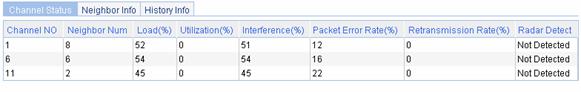
2. On the Operations tab, click the Channel Status tab.
3. Click the desired radio to enter the page for displaying channel status.
|
Item |
Description |
|
Channel No |
Running channel. |
|
Neighbor Num |
Number of neighbors on a channel. |
|
Load (%) |
Load detected on a channel. |
|
Utilization (%) |
Channel utilization. |
|
Interference (%) |
Interference detected on a channel. |
|
Packet Error Rate (%) |
Error rate for packets on a channel. |
|
Retransmission Rate (%) |
Retransmission rate on a channel. |
|
Radar Detect |
Radar detection status. |
Displaying neighbor information
1. Select Radio > Calibration from the navigation tree.
2. On the Operations tab, click the Neighbor Info tab.
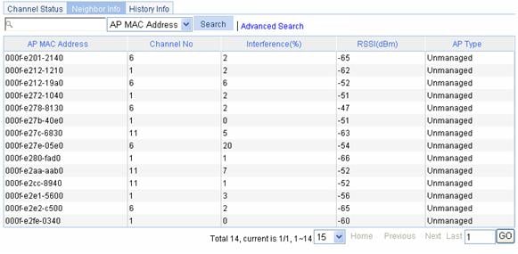
3. Click the desired radio to enter the page for displaying neighbor information.
Figure 15 Neighbor information
|
Field |
Description |
|
AP MAC Address |
MAC address of an AP. |
|
Channel No |
Running channel. |
|
Interference (%) |
Interference detected on a channel. |
|
RSSI (dBm) |
Received signal strength indication (RSSI) of AP, in dBm. |
|
AP Type |
AP type, managed or unmanaged. |
Displaying history information
|
|
NOTE: History information is available only if channel switching or power adjustment occurs after RRM is enabled. |
1. Select Radio > Calibration from the navigation tree.
2. On the Operations tab, click History Info.
3. Click the desired radio to enter the page for displaying neighbor information.
Figure 16 History information
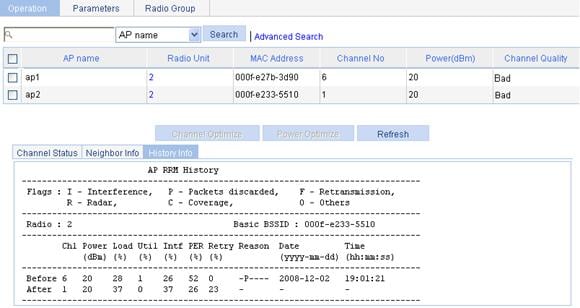
Table 12 Field description
|
Field |
Description |
|
Radio |
Radio ID of the AP. |
|
Basic BSSID |
MAC address of the AP. |
|
Chl |
Channel on which the radio operates in case of the change of channel or power. |
|
Power |
Power of the radio in case of the change of channel or power. |
|
Load |
Load observed on the radio in percentage in case of the change of channel or power. |
|
Util |
Utilization of the radio in percentage in case of the change of channel or power. |
|
Intf |
Interference observed on the radio in percentage in case of the change of channel or power. |
|
PER |
Packet error rate observed on a channel, in percentage. |
|
Retry |
Percentage of retransmission happened on the radio before/after the change of channel or power. |
|
Reason |
Reason for the change of channel or power, such as Interference, packets discarded, retransmission, radar or coverage. |
|
Date |
Date when the channel or power change occurred. |
|
Time |
Time when the channel or power change occurred. |
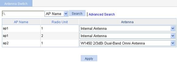
Antenna
1. Select Radio > Antenna to select an appropriate antenna for the corresponding radio.
2. Select the antenna type, Internal Antenna, or User-Default external antenna, for a specific radio from the Antenna list.
3. Click Apply.
Figure 17 Antenna switch
Manual channel adjustment configuration example
Network requirements
As shown in Figure 18, configure manual channel adjustment on the AC so that the AC can perform manual channel adjustment when the channel of AP 1 is unavailable.
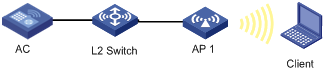
Configuration procedure
1. Before you configure manual channel adjustment, configure AP 1 on the AC to establish a connection between them.
For the related configuration, see "Access service configuration."
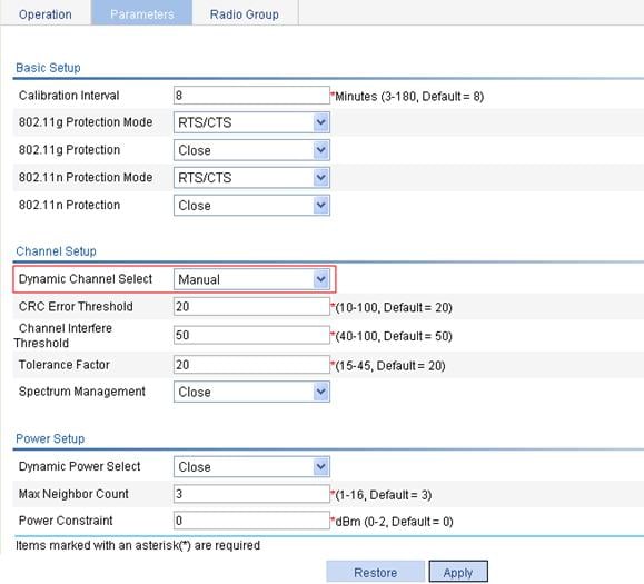
2. Configure manual channel adjustment:
a. Select Radio > Calibration from the navigation tree.
b. Select the Parameters tab.
c. Select Manual from the Dynamic Channel Select list.
d. Click Apply.
Figure 19 Configuring manual channel adjustment
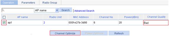
3. Perform manual channel adjustment:
a. Select Radio > Calibration from the navigation tree.
b. On the Operation tab, select the box of the target radio.
c. Click Channel Optimize..
Figure 20 Performing manual channel adjustment
Verifying the configuration
· You can view the channel status on the Operation tab you enter by selecting Radio > Calibration from the navigation tree.
· After you perform manual channel calibration, the AC informs the adjusted channel to the AP after a calibration interval.
· You can view the detailed information, such as the specific reason for channel adjustment on the History Info tab you enter by selecting Radio > Calibration from the navigation tree, clicking Operation, and then clicking History Info.
Configuration guidelines
If you select manual channel adjustment, click Channel Optimize on the Operation tab every time you perform manual channel adjustment.
Automatic power adjustment configuration example
Network requirements
As shown in Figure 21, AP 1 through AP 3 are connected to the AC. Configure automatic power adjustment and specify the adjacency factor as 3 on the AC. In this way, when AP 4 joins, the AC performs automatic power adjustment to avoid interference.
Configuration procedure
1. Before you configure automatic power adjustment, configure AP 1 through AP 3 on the AC to establish a connection between the AC and each AP.
For the related configuration, see "Access service configuration."
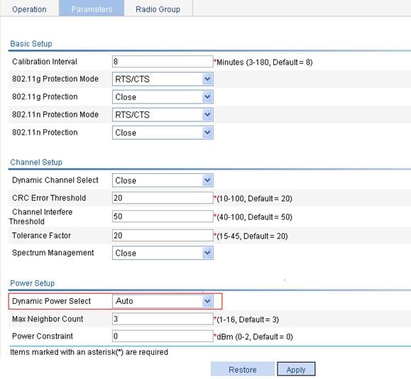
2. Configure automatic power adjustment:
a. Select Radio > Calibration from the navigation tree.
b. Click the Parameters tab.
c. Select Auto from the Dynamic Power Select list.
d. Click Apply.
Figure 22 Configuring automatic power adjustment
Verifying the configuration
· You can view the power of each AP on the Operation tab you enter by selecting Radio > Calibration from the navigation tree.
· When AP 4 joins (the adjacency number becomes 3), the maximum number of neighbors reaches the upper limit (3 by default), and the AC performs power adjustment after the calibration interval. You can view the detailed information, such as decrease of the Tx power value, on the History Info tab you enter by selecting Radio > Calibration from the navigation tree, selecting the Operation tab, and then selecting History Info.
Radio group configuration example
Network requirements
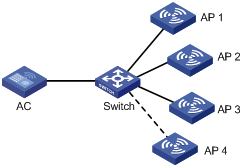
As shown in Figure 23, AP 1 through AP 3 are connected to the AC.
· Configure automatic channel adjustment so that the AC can automatically switch the channel when the signal quality on a channel is degraded to a certain level.
· Configure automatic power adjustment so that the AC can automatically adjust the power when the third neighbor is discovered (or in other words, when AP 4 joins) to avoid interference.
· Add radio 2 of AP 1 and radio 2 of AP 2 to a radio group to prevent frequent channel or power adjustments for the radios.
Configuration procedure
1. Before you configure a radio group, configure AP 1 through AP 3 on the AC to establish a connection between the AC and each AP.
For the related configuration, see "Access service configuration."
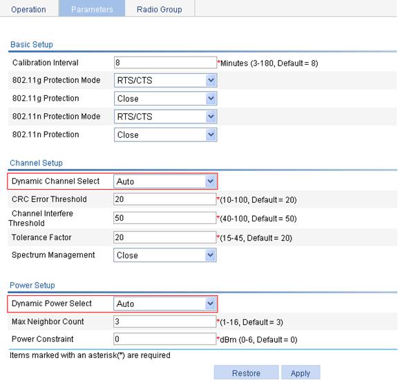
2. Configure automatic channel and power adjustment:
a. Select Radio > Calibration from the navigation tree.
b. Click the Parameters tab.
c. Select Auto from the Dynamic Channel Select list, select Auto from the Dynamic Power Select list, and click Apply.
Figure 24 Configuring automatic channel and power adjustment
3. Configure a radio group:
a. Select Radio > Calibration from the navigation tree.
b. Click Radio Group.
c. Click Add.
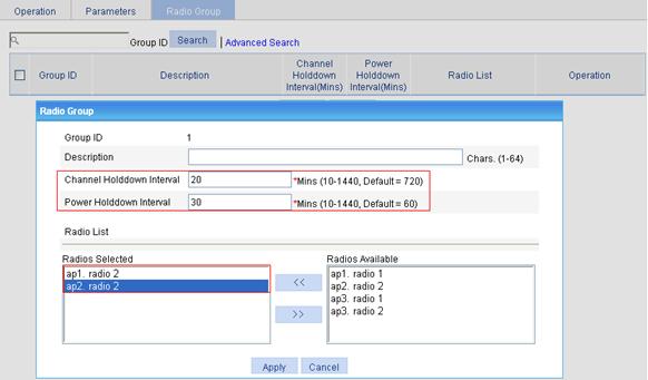
d. On the page that appears, enter the channel holddown interval 20 and enter the power holddown interval 30.
e. In the Radios Available area, select the target radios and click << to add them into the Radios Selected area.
f. Click Apply.
Figure 25 Configuring the radio group
Verifying the configuration
· The working channel of radio 2 of AP 1 and that of radio 2 of AP 2 do not change within 20 minutes after each automatic channel adjustment.
· The power of radio 2 of AP 1 and that of radio 2 of AP 2 do not change within 30 minutes after each automatic power adjustment.
