- Table of Contents
-
- H3C Fixed Port Campus Switches Configuration Examples-B70D022-6W100
- 01-Login Management Configuration Examples
- 02-RBAC Configuration Examples
- 03-Software Upgrade Examples
- 04-ISSU Configuration Examples
- 05-Software Patching Examples
- 06-Ethernet Link Aggregation Configuration Examples
- 07-Port Isolation Configuration Examples
- 08-Spanning Tree Configuration Examples
- 09-VLAN Configuration Examples
- 10-VLAN Tagging Configuration Examples
- 11-DHCP Snooping Configuration Examples
- 12-Cross-Subnet Dynamic IP Address Allocation Configuration Examples
- 13-IPv6 over IPv4 Manual Tunneling with OSPFv3 Configuration Examples
- 14-ISATAP Tunnel and 6to4 Tunnel Configuration Examples
- 15-GRE Tunnel Configuration Examples
- 16-GRE with OSPF Configuration Examples
- 17-OSPF Configuration Examples
- 18-IS-IS Configuration Examples
- 19-BGP Configuration Examples
- 20-Policy-Based Routing Configuration Examples
- 21-OSPFv3 Configuration Examples
- 22-IPv6 IS-IS Configuration Examples
- 23-Routing Policy Configuration Examples
- 24-IGMP Snooping Configuration Examples
- 25-IGMP Configuration Examples
- 26-BIDIR-PIM Configuration Examples
- 27-Multicast VPN Configuration Examples
- 28-MLD Snooping Configuration Examples
- 29-IPv6 Multicast VLAN Configuration Examples
- 30-Basic MPLS Configuration Examples
- 31-MPLS L3VPN Configuration Examples
- 32-ACL Configuration Examples
- 33-Control Plane-Based QoS Policy Configuration Examples
- 34-Traffic Policing Configuration Examples
- 35-GTS and Rate Limiting Configuration Examples
- 36-Priority Mapping and Queue Scheduling Configuration Examples
- 37-Traffic Filtering Configuration Examples
- 38-AAA Configuration Examples
- 39-Port Security Configuration Examples
- 40-Portal Configuration Examples
- 41-SSH Configuration Examples
- 42-IP Source Guard Configuration Examples
- 43-Ethernet OAM Configuration Examples
- 44-CFD Configuration Examples
- 45-DLDP Configuration Examples
- 46-VRRP Configuration Examples
- 47-BFD Configuration Examples
- 48-NTP Configuration Examples
- 49-SNMP Configuration Examples
- 50-NQA Configuration Examples
- 51-Mirroring Configuration Examples
- 52-sFlow Configuration Examples
- 53-OpenFlow Configuration Examples
- 54-MAC Address Table Configuration Examples
- 55-Static Multicast MAC Address Entry Configuration Examples
- 56-IP Unnumbered Configuration Examples
- 57-MVRP Configuration Examples
- 58-MCE Configuration Examples
- 59-Congestion Avoidance and Queue Scheduling Configuration Examples
- 60-Attack Protection Configuration Examples
- 61-Smart Link Configuration Examples
- 62-RRPP Configuration Examples
- 63-BGP Route Selection Configuration Examples
- 64-IS-IS Route Summarization Configuration Examples
- 65-IRF Configuration Examples
- 66-MPLS TE Configuration Examples
- 67-VXLAN Configuration Examples
- 68-VCF Fabric Configuration Examples
- Related Documents
-
| Title | Size | Download |
|---|---|---|
| 65-IRF Configuration Examples | 412.36 KB |
General restrictions and guidelines
IRF physical interface requirements
Example: Setting up a four-chassis LACP MAD-enabled IRF fabric
Network connectivity configuration
Applicable hardware and software versions
Restrictions and guidelines for LACP MAD configuration
Restrictions and guidelines for IRF physical interfaces
Setting up the access-layer IRF fabric
Configuring network connectivity settings
Verifying the link backup function of multichassis aggregations
Verifying link failure protection of the ring topology
Verifying the LACP MAD configuration
Introduction
This document provides examples for setting up IRF fabrics and configuring link aggregation and routing on the IRF fabrics.
Prerequisites
The configuration examples in this document were created and verified in a lab environment, and all the devices were started with the factory default configuration. When you are working on a live network, make sure you understand the potential impact of every command on your network.
This document assumes that you have basic knowledge of IRF.
General restrictions and guidelines
When you set up and configure an IRF fabric, follow the restrictions and guidelines in this section.
This section provides only the basic restrictions and guidelines that ensure a successful IRF deployment. For more information, see IRF configuration in the configuration guides for your devices.
Hardware requirements
The applicable switches in the IRF configuration examples can form an IRF fabric only with switches in the same series.
Software requirements
All IRF member devices must run the same system software version.
IRF physical interface requirements
Requirements for IRF physical interfaces vary by device model. To establish an IRF fabric successfully, use the installation guide for your device to identify the IRF physical interface requirements, including:
· Interfaces that can be used for IRF connections.
· Interface grouping status on the device. Typically, if you use one physical interface in a group as an IRF physical interface, you cannot use the remaining physical interfaces in the group for any other purposes than IRF connection.
· Compatible transceiver modules and cables.
Connecting IRF ports
When you connect two neighboring IRF members, connect the physical interfaces of IRF-port 1 on one member to the physical interfaces of IRF-port 2 on the other.
Example: Setting up a four-chassis LACP MAD-enabled IRF fabric
Network configuration
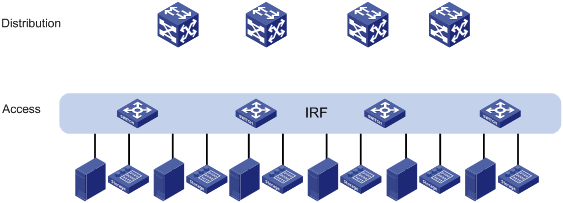
As shown in Figure 2, use a four-chassis IRF fabric to replace the ToR switches in Figure 1 at the access layer. The access-layer IRF fabric provides Layer 2 forwarding services.
Run LACP MAD to detect IRF split.
Figure 1 Network diagram before IRF deployment
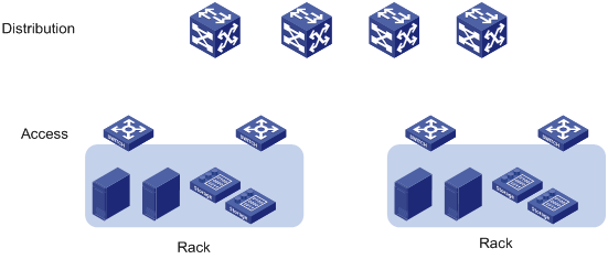
Figure 2 Network diagram after IRF deployment
Analysis
The requirements in this example include the following categories:
· Network connectivity configuration
IRF setup
To set up an IRF fabric, determine the items in Table 1.
|
Item |
Analysis |
Choice in this example |
|
Topology |
You can use a ring or daisy-chain topology for a three- or four-chassis IRF fabric. For reliability, use the ring topology. |
Ring topology (see Figure 3). |
|
Member ID assignment |
IRF member IDs must be unique. |
Device A—1. Device B—2. Device C—3. Device D—4. |
|
Master device |
IRF members elect a master automatically. For a member device to be elected the master, assign it the highest member priority. |
Device A. |
|
IRF port bindings |
Make sure the IRFport bindings are consistent with the physical connections. For high availability, bind multiple physical interfaces to an IRF port. These ports will automatically aggregate for load balancing and redundancy. |
See Table 2. |
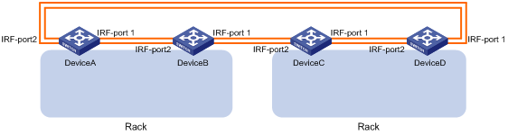
Table 2 IRF physical interface bindings
|
IRF physical interfaces |
|
|
Device A: |
|
|
IRF-port 1 |
GigabitEthernet 1/0/51 GigabitEthernet 1/0/52 |
|
IRF-port 2 |
GigabitEthernet 1/0/53 GigabitEthernet 1/0/54 |
|
Device B: |
|
|
IRF-port 1 |
GigabitEthernet 2/0/51 GigabitEthernet 2/0/52 |
|
IRF-port 2 |
GigabitEthernet 2/0/53 GigabitEthernet 2/0/54 |
|
Device C: |
|
|
IRF-port 1 |
GigabitEthernet 3/0/51 GigabitEthernet 3/0/52 |
|
IRF-port 2 |
GigabitEthernet 3/0/53 GigabitEthernet 3/0/54 |
|
Device D: |
|
|
IRF-port 1 |
GigabitEthernet 4/0/51 GigabitEthernet 4/0/52 |
|
IRF-port 2 |
GigabitEthernet 4/0/53 GigabitEthernet 4/0/54 |
|
|
NOTE: The first segment in a physical interface number is the IRF member ID. By default, the IRF member ID is 1. Table 2 shows the interface numbers after the member IDs are changed. |
LACP MAD configuration
|
|
IMPORTANT: For LACP MAD to run correctly, you must make sure the intermediate device supports extended LACPDUs for LACP MAD. |
To run LACP MAD, the IRF fabric and intermediate device must each have a dynamic Ethernet link aggregation. LACP MAD cannot run on a static link aggregation.
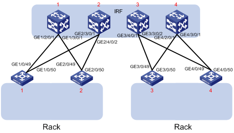
If the intermediate device is also an IRF fabric, you must configure MAD for both IRF fabrics, and assign the two IRF fabrics different domain IDs for correct split detection. This example uses a four-chassis IRF fabric at the distribution layer. The access-layer and distribution-layer IRF fabrics are the intermediate device of each other, as shown in Figure 4.
In this example, each member in the access-layer IRF fabric has only two links to the distribution-layer IRF fabric. For high availability, you can connect each member in the access-layer IRF fabric to each member in the distribution-layer IRF fabric. After you aggregate these links, they are regarded as one link in the topology.
For quick split detection, assign high-speed ports for uplink aggregation connections. This example uses GE ports.
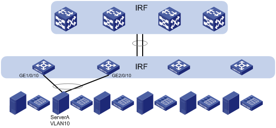
Network connectivity configuration
In a Layer 2 network, IRF is typically used with link aggregation to simplify the network topology.
For high availability, you can connect each host or server to two ToR switches in the access-layer IRF fabric, and aggregate the links. On each link aggregation, you do not need to run the spanning tree protocol feature because an IRF fabric appears as one node in the network.
For VLAN tags to be processed correctly, assign ports and aggregate interfaces to the correct VLANs.
|
|
NOTE: A link aggregation could span one member device, some of the member devices, or all member devices, depending on the link redundancy requirements and number of available links. The link aggregation used for LACP MAD must span all member devices. |
Figure 5 Connection diagram for the IRF fabrics in a Layer 2 network
Applicable hardware and software versions
The following matrix shows the hardware and software versions to which this configuration example is applicable:
|
Hardware |
Software version |
|
S6520XE-HI switch series |
Supported in Release 11xx |
|
S5560X-EI switch series |
Supported in Release 111x |
|
S5500V2-EI switch series |
Supported in Release 111x |
|
MS4520V2-30F switch |
Supported in Release 111x |
|
S5560S-EI switch series S5560S-SI switch series |
Supported in Release 612x |
|
S5130S-HI switch series S5130S-EI switch series S5130S-SI switch series S5130S-LI switch series |
Supported in Release 612x |
|
S5120V2-SI switch series S5120V2-LI switch series |
Supported in Release 612x |
|
S3100V3-EI switch series S3100V3-SI switch series |
Supported in Release 612x |
|
S5110V2 switch series |
Supported in Release 612x |
|
S5110V2-SI switch series |
Supported in Release 612x |
|
S5000V3-EI switch series |
Supported in Release 612x |
|
S5000E-X switch series |
Supported in Release 612x |
|
WAS6000 switch series |
Supported in Release 612x |
|
E128C switch E152C switch E500C switch series E500D switch series |
Supported in Release 612x |
|
MS4520V2 switch series (except the MS4520V2-30F switch) |
Supported in Release 612x |
|
MS4320V2 switch series MS4300V2 switch series MS4320 switch series MS4200 switch series |
Supported in Release 612x |
|
WS5850-WiNet switch series |
Not supported |
|
WS5820-WiNet switch series |
Not supported |
|
WS5810-WiNet switch series |
Not supported |
Restrictions and guidelines
Restrictions and guidelines for LACP MAD configuration
When you configure LACP MAD, follow these restrictions and guidelines:
· You only need to run LACP MAD on a single link aggregation for IRF split detection.
· The link aggregation must use dynamic aggregation mode.
· The link aggregation must have a minimum of one member link from each member device.
Restrictions and guidelines for IRF physical interfaces
Make sure all IRF physical interfaces are operating in bridge mode (the default).
Procedures
This example assumes that the distribution-layer IRF fabric has been set up.
Setting up the access-layer IRF fabric
1. Configure Device A:
# Shut down the physical interfaces used for IRF connection. This example uses the port group that contains GigabitEthernet 1/0/51 to GigabitEthernet 1/0/54 for IRF connection.
<DeviceA> system-view
[DeviceA] interface range gigabitethernet 1/0/51 to gigabitethernet 1/0/54
[DeviceA-if-range] shutdown
[DeviceA-if-range] quit
# Bind GigabitEthernet 1/0/51 and GigabitEthernet 1/0/52 to IRF-port 1/1.
[DeviceA] irf-port 1/1
[DeviceA-irf-port1/1] port group interface gigabitethernet 1/0/51
[DeviceA-irf-port1/1] port group interface gigabitethernet 1/0/52
[DeviceA-irf-port1/1] quit
# Bind GigabitEthernet 1/0/53 and GigabitEthernet 1/0/54 to IRF-port 1/2.
[DeviceA] irf-port 1/2
[DeviceA-irf-port1/2] port group interface gigabitethernet 1/0/53
[DeviceA-irf-port1/2] port group interface gigabitethernet 1/0/54
[DeviceA-irf-port1/2] quit
# Bring up the physical interfaces.
[DeviceA] interface range gigabitethernet 1/0/51 to gigabitethernet 1/0/54
[DeviceA-if-range] undo shutdown
[DeviceA-if-range] quit
# Assign IRF member priority 31 to Device A. This priority is high enough to ensure that Device A can be elected as the master.
[DeviceA] irf member 1 priority 31
# Save the running configuration.
[DeviceA] quit
<DeviceA> save
# Activate the IRF port configuration.
<DeviceA> system-view
[DeviceA] irf-port-configuration active
2. Configure Device B:
# Assign member ID 2 to Device B, and reboot the device to effect the member ID change.
<DeviceB> system-view
[DeviceB] irf member 1 renumber 2
Renumbering the member ID may result in configuration change or loss. Continue? [Y/N]:y
[DeviceB] quit
<DeviceB> reboot
# Shut down the physical interfaces used for IRF connection. This example uses the port group that contains GigabitEthernet 2/0/51 to GigabitEthernet 2/0/54 for IRF connection.
<DeviceB> system-view
[DeviceB] interface range gigabitethernet 2/0/51 to gigabitethernet 2/0/54
[DeviceB-if-range] shutdown
[DeviceB-if-range] quit
# Bind GigabitEthernet 2/0/51 and GigabitEthernet 2/0/52 to IRF-port 2/1.
[DeviceB] irf-port 2/1
[DeviceB-irf-port2/1] port group interface gigabitethernet 2/0/51
[DeviceB-irf-port2/1] port group interface gigabitethernet 2/0/52
[DeviceB-irf-port2/1] quit
# Bind GigabitEthernet 2/0/53 and GigabitEthernet 2/0/54 to IRF-port 2/2.
[DeviceB] irf-port 2/2
[DeviceB-irf-port2/2] port group interface gigabitethernet 2/0/53
[DeviceB-irf-port2/2] port group interface gigabitethernet 2/0/54
[DeviceB-irf-port2/2] quit
# Bring up the physical interfaces.
[DeviceB] interface range gigabitethernet 2/0/51 to gigabitethernet 2/0/54
[DeviceB-if-range] undo shutdown
[DeviceB-if-range] quit
# Save the running configuration.
[DeviceB] quit
<DeviceB> save
# Connect Device B to Device A, as shown in Figure 3.
# Activate the IRF port configuration.
<DeviceB> system-view
[DeviceB] irf-port-configuration active
Device B has a lower priority than Device A, and Device B fails master election and reboots. A two-chassis IRF fabric is formed.
3. Configure Device C:
# Assign member ID 3 to Device C, and reboot the device to effect the member ID change.
<DeviceC> system-view
[DeviceC] irf member 1 renumber 3
Renumbering the member ID may result in configuration change or loss. Continue? [Y/N]:y
[DeviceC] quit
<DeviceC> reboot
# Shut down the physical interfaces used for IRF connection. This example uses the port group that contains GigabitEthernet 3/0/51 to GigabitEthernet 3/0/54 for IRF connection.
<DeviceC> system-view
[DeviceC] interface range gigabitethernet 3/0/51 to gigabitethernet 3/0/54
[DeviceC-if-range] shutdown
[DeviceC-if-range] quit
# Bind GigabitEthernet 3/0/51 and GigabitEthernet 3/0/52 IRF-port 3/1.
[DeviceC] irf-port 3/1
[DeviceC-irf-port3/1] port group interface gigabitethernet 3/0/51
[DeviceC-irf-port3/1] port group interface gigabitethernet 3/0/52
[DeviceC-irf-port3/1] quit
# Bind GigabitEthernet 3/0/53 and GigabitEthernet 3/0/54 to IRF-port 3/2.
[DeviceC] irf-port 3/2
[DeviceC-irf-port3/2] port group interface gigabitethernet 3/0/53
[DeviceC-irf-port3/2] port group interface gigabitethernet 3/0/54
[DeviceC-irf-port3/2] quit
# Bring up the physical interfaces.
[DeviceC] interface range gigabitethernet 3/0/51 to gigabitethernet 3/0/54
[DeviceC-if-range] undo shutdown
[DeviceC-if-range] quit
# Save the running configuration.
[DeviceC] quit
<DeviceC> save
# Connect Device C to Device B, as shown in Figure 3.
# Activate the IRF port configuration.
<DeviceC> system-view
[DeviceC] irf-port-configuration active
Device C reboots to join the IRF fabric. A three-chassis IRF fabric is formed.
4. Configure Device D:
# Assign member ID 4 to Device D, and reboot the device to effect the member ID change.
<DeviceD> system-view
[DeviceD] irf member 1 renumber 4
Renumbering the member ID may result in configuration change or loss. Continue? [Y/N]:y
[DeviceD] quit
<DeviceD> reboot
# Shut down the physical interfaces used for IRF connection. This example uses the port group that contains GigabitEthernet 4/0/51 to GigabitEthernet 4/0/54 for IRF connection.
<DeviceD> system-view
[DeviceD] interface range gigabitethernet 4/0/51 to gigabitethernet 4/0/54
[DeviceD-if-range] shutdown
[DeviceD-if-range] quit
# Bind GigabitEthernet 4/0/51 and GigabitEthernet 4/0/52 to IRF-port 4/1.
[DeviceD] irf-port 4/1
[DeviceD-irf-port4/1] port group interface gigabitethernet 4/0/51
[DeviceD-irf-port4/1] port group interface gigabitethernet 4/0/52
[DeviceD-irf-port4/1] quit
# Bind GigabitEthernet 4/0/53 and GigabitEthernet 4/0/54 to IRF-port 4/2.
[DeviceD] irf-port 4/2
[DeviceD-irf-port4/2] port group interface gigabitethernet 4/0/53
[DeviceD-irf-port4/2] port group interface gigabitethernet 4/0/54
[DeviceD-irf-port4/2] quit
# Bring up the physical interfaces.
[DeviceD] interface range gigabitethernet 4/0/51 to gigabitethernet 4/0/54
[DeviceD-if-range] undo shutdown
[DeviceD-if-range] quit
# Save the running configuration.
[DeviceD] quit
<DeviceD> save
# Connect Device D to Device A and Device C, as shown in Figure 3.
# Activate the IRF port configuration.
<DeviceD> system-view
[DeviceD] irf-port-configuration active
Device D reboots to join the IRF fabric. A four-chassis IRF fabric is formed. The command prompt changes to the name of Device A (the master).
5. Change the name of the IRF fabric.
<DeviceA> system-view
[DeviceA] sysname IRF
[IRF]
Configuring LACP MAD
1. Configure the IRF fabric at the access layer:
# Assign domain ID 1 to the IRF fabric.
<IRF> system-view
[IRF] irf domain 1
# Create Bridge-Aggregation 2, set its aggregation mode to dynamic, and enable LACP MAD.
[IRF] interface bridge-aggregation 2
[IRF-Bridge-Aggregation2] link-aggregation mode dynamic
[IRF-Bridge-Aggregation2] mad enable
You need to assign a domain ID (range: 0-4294967295)
[Current domain is: 1]:
The assigned domain ID is: 1
Info: MAD LACP only enable on dynamic aggregation interface.
[IRF-Bridge-Aggregation2] quit
# Create a named interface range that contains uplink ports to the distribution layer IRF fabric. In this example, the interface range name is lacp, and each member device has two links to the distribution layer IRF fabric.
[IRF] interface range name lacp interface gigabitethernet 1/0/49 to gigabitethernet 1/0/50 gigabitethernet 2/0/49 to gigabitethernet 2/0/50 gigabitethernet 3/0/49 to gigabitethernet 3/0/50 gigabitethernet 4/0/49 to gigabitethernet 4/0/50
# Assign the ports in the interface range to Bridge-Aggregation 2.
[IRF-if-range-lacp] port link-aggregation group 2
[IRF-if-range-lacp] quit
2. Configure the IRF fabric at the distribution layer:
# Assign IRF domain ID 2 to the IRF fabric.
<Sysname> system-view
[Sysname] irf domain 2
# Create Bridge-Aggregation 2, set its aggregation mode to dynamic, and enable LACP MAD.
[Sysname] interface bridge-aggregation 2
[Sysname-Bridge-Aggregation2] link-aggregation mode dynamic
[Sysname-Bridge-Aggregation2] mad enable
You need to assign a domain ID (range: 0-4294967295)
[Current domain is: 2]:
The assigned domain ID is: 2
Info: MAD LACP only enable on dynamic aggregation interface.
[Sysname-Bridge-Aggregation2] quit
# Assign the downlink ports that connect to the access-layer IRF fabric to Bridge-Aggregation 2.
[Sysname] interface gigabitethernet 1/2/0/1
[Sysname-GigabitEthernet1/2/0/1] port link-aggregation group 2
[Sysname-GigabitEthernet1/2/0/1] quit
[Sysname] interface gigabitethernet 1/3/0/1
[Sysname-GigabitEthernet1/3/0/1] port link-aggregation group 2
[Sysname-GigabitEthernet1/3/0/1] quit
[Sysname] interface gigabitethernet 2/3/0/1
[Sysname-GigabitEthernet2/3/0/1] port link-aggregation group 2
[Sysname-GigabitEthernet2/3/0/1] quit
[Sysname] interface gigabitethernet 2/4/0/2
[Sysname-GigabitEthernet2/4/0/2] port link-aggregation group 2
[Sysname-GigabitEthernet2/4/0/2] quit
[Sysname] interface gigabitethernet 3/4/0/1
[Sysname-GigabitEthernet3/4/0/1] port link-aggregation group 2
[Sysname-GigabitEthernet3/4/0/1] quit
[Sysname] interface gigabitethernet 3/3/0/2
[Sysname-GigabitEthernet3/3/0/2] port link-aggregation group 2
[Sysname-GigabitEthernet3/3/0/2] quit
[Sysname] interface gigabitethernet 4/2/0/1
[Sysname-GigabitEthernet4/2/0/1] port link-aggregation group 2
[Sysname-GigabitEthernet4/2/0/1] quit
[Sysname] interface gigabitethernet 4/3/0/1
[Sysname-GigabitEthernet4/3/0/1] port link-aggregation group 2
[Sysname-GigabitEthernet4/3/0/1] quit
Configuring network connectivity settings
This section provides the VLAN and link aggregation configuration procedure for end devices (for example, a server in VLAN 10).
1. Configure the IRF fabric at the access layer:
# Create VLAN 10.
<IRF> system-view
[IRF] vlan 10
# Create Bridge-Aggregation 3, and set its aggregation mode to dynamic.
[IRF] interface bridge-aggregation 3
[IRF-Bridge-Aggregation3] link-aggregation mode dynamic
[IRF-Bridge-Aggregation3] quit
# Assign GigabitEthernet 1/0/10 and GigabitEthernet 2/0/10 to the aggregation group for Bridge-Aggregation 3.
[IRF] interface gigabitethernet 1/0/10
[IRF-GigabitEthernet1/0/10] port link-aggregation group 3
[IRF-GigabitEthernet1/0/10] quit
[IRF] interface gigabitethernet 2/0/10
[IRF-GigabitEthernet2/0/10] port link-aggregation group 3
[IRF-GigabitEthernet2/0/10] quit
# Assign Bridge-Aggregation 3 to VLAN 10.
[IRF] interface bridge-aggregation 3
[IRF-Bridge-Aggregation3] port access vlan 10
[IRF-Bridge-Aggregation3] quit
# Configure Bridge-Aggregation 2 as a trunk port, and assign it to VLAN 10.
[IRF] interface bridge-aggregation 2
[IRF-Bridge-Aggregation2] port link-type trunk
[IRF-Bridge-Aggregation2] port trunk permit vlan 10
[IRF-Bridge-Aggregation2] quit
2. Configure the IRF fabric at the distribution layer:
# Create VLAN 10.
<Sysname> system-view
[Sysname] vlan 10
# Configure Bridge-Aggregation 2 as a trunk port, and assign it to VLAN 10.
[Sysname] interface bridge-aggregation 2
[Sysname-Bridge-Aggregation2] port link-type trunk
[Sysname-Bridge-Aggregation2] port trunk permit vlan 10
[Sysname-Bridge-Aggregation2] quit
Verifying the configuration
Verify the IRF setup, multichassis link aggregations, ring topology, and LACP MAD.
Verifying the IRF setup
# Verify that the IRF fabric has been formed.
[IRF] display irf
MemberID Role Priority CPU-Mac Description
*+1 Master 31 00e0-fc0f-8c02 ---
2 Standby 1 00e0-fc0f-8c03 ---
3 Standby 1 00e0-fc0f-8c04 ---
4 Standby 1 00e0-fc0f-8c05 ---
--------------------------------------------------
* indicates the device is the master.
+ indicates the device through which the user logs in.
The Bridge MAC of the IRF is: 0cda-414a-859b
Auto upgrade : yes
Mac persistent : 6 min
Domain ID : 1
IRF mode : normal
The output shows that the IRF fabric has four member devices.
# Verify IRF fabric connectivity.
[IRF] display irf topology
Topology Info
-------------------------------------------------------------------------
IRF-Port1 IRF-Port2
MemberID Link neighbor Link neighbor Belong To
1 UP 2 UP 4 0cda-414a-859b
2 UP 3 UP 1 0cda-414a-859b
3 UP 4 UP 2 0cda-414a-859b
4 UP 1 UP 3 0cda-414a-859b
The output shows that all the IRF links are in UP state. The four-chassis IRF fabric is established.
Verifying the link backup function of multichassis aggregations
# Ping the IP address of the IRF fabric at the distribution layer from a server.
C:\Users>ping 10.153.116.111 –t
# On the IRF fabric at the access layer, shut down GigabitEthernet 1/0/10, a member port of Bridge-Aggregation 3.
[IRF] interface gigabitethernet 1/0/10
[IRF-GigabitEthernet1/0/10] shutdown
[IRF-GigabitEthernet1/0/10] quit
# Observe the output on the server configuration terminal.
Pinging 10.153.116.111 with 32 bytes of data:
Reply from 10.153.116.111: bytes=32 time<1ms TTL=128
Reply from 10.153.116.111: bytes=32 time<1ms TTL=128
Request timed out.
Reply from 10.153.116.111: bytes=32 time<1ms TTL=128
Reply from 10.153.116.111: bytes=32 time<1ms TTL=128
The output shows that the IP address can be pinged after transient traffic disruption.
# On the IRF fabric at the access layer, shut down GigabitEthernet 1/0/49 and GigabitEthernet 1/0/50 (member ports of Bridge-Aggregation 2). The server cannot access the distribution layer through Device A.
[IRF] interface range gigabitethernet 1/0/49 gigabitethernet 1/0/50
[IRF-if-range] shutdown
[IRF-if-range] quit
# Observe the output on the server configuration terminal.
Pinging 10.153.116.111 with 32 bytes of data:
Reply from 10.153.116.111: bytes=32 time<1ms TTL=128
Reply from 10.153.116.111: bytes=32 time<1ms TTL=128
Request timed out.
Reply from 10.153.116.111: bytes=32 time<1ms TTL=128
Reply from 10.153.116.111: bytes=32 time<1ms TTL=128
The output shows that the IP address can be pinged after transient traffic disruption. The server accesses the distribution layer through another device in the access-layer IRF fabric.
Verifying link failure protection of the ring topology
# Disconnect all IRF links between two IRF member devices. (Details not shown.)
# Verify that the IRF fabric operates correctly in daisy-chain topology. (Details not shown.)
Verifying the LACP MAD configuration
# As shown in Figure 6, disconnect two IRF connections: one between Device A and Device D, and the other between Device B and Device C. The disconnect actions cause the IRF fabric to break up into two parts.
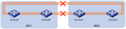
# Observe the output messages to verify that LACP MAD takes the following actions:
· Changes IRF 2 (Device C and Device D) to the Recovery state, because the master device in IRF 1 has a lower member ID than the master device in IRF 2.
· Shuts down all service interfaces on Device C and Device D, except for the IRF physical interfaces and the service interfaces excluded from the MAD shutdown action.
The following is the sample output on IRF 1:
%Jan 1 05:19:10:176 2018 H3C STM/3/STM_LINK_STATUS_DOWN: IRF port 2 is down.
%Jan 1 05:19:10:184 2018 H3C IFNET/3/PHY_UPDOWN: GigabitEthernet1/0/53 link status is down.
%Jan 1 05:19:10:184 2018 H3C IFNET/3/PHY_UPDOWN: GigabitEthernet1/0/54 link status is down.
%Jan 1 05:19:10:176 2018 H3C STM/3/STM_LINK_STATUS_DOWN: IRF port 1 is down.
%Jan 1 05:19:10:184 2018 H3C IFNET/3/PHY_UPDOWN: GigabitEthernet2/0/51 link status is down.
%Jan 1 05:19:10:184 2018 H3C IFNET/3/PHY_UPDOWN: GigabitEthernet2/0/52 link status is down.
%Jan 1 05:19:10:186 2018 H3C DEV/3/BOARD_REMOVED: Board is removed from Slot 3, type is MAIN_BOARD_TYPE_54QT.
%Jan 1 05:19:10:186 2018 H3C DEV/3/BOARD_REMOVED: Board is removed from Slot 4, type is MAIN_BOARD_TYPE_54QT.
The following is the sample output from IRF 2:
%Jan 1 05:53:20:784 2018 H3C HA/5/HA_STANDBY_TO_MASTER: Standby board in slot 3 changes to master.
%Jan 1 05:53:20:831 2018 H3C DEV/3/BOARD_REMOVED: Board is removed from Slot 1, type is MAIN_BOARD_TYPE_54QT.
%Jan 1 05:53:20:831 2018 H3C DEV/3/BOARD_REMOVED: Board is removed from Slot 2, type is MAIN_BOARD_TYPE_54QT.
%Jan 1 05:53:20:860 2018 H3C DEV/1/MAD_DETECT: Multi-active devices detected, please fix it.
%Jan 1 05:53:20:886 2018 H3C IFNET/3/PHY_UPDOWN: M-GigabitEthernet0/0/0 link status is down.
%Jan 1 05:53:20:887 2018 H3C IFNET/5/LINK_UPDOWN: Line protocol on the interface M-GigabitEthernet0/0/0 is down.
%Jan 1 05:53:20:912 2018 H3C IFNET/3/PHY_UPDOWN: GigabitEthernet3/0/49 link status is down.
%Jan 1 05:53:20:914 2018 H3C IFNET/5/LINK_UPDOWN: Line protocol on the interface GigabitEthernet3/0/49 is down.
%Jan 1 05:53:20:912 2018 H3C IFNET/3/PHY_UPDOWN: GigabitEthernet3/0/50 link status is down.
%Jan 1 05:53:20:914 2018 H3C IFNET/5/LINK_UPDOWN: Line protocol on the interface GigabitEthernet3/0/49 is down.
%Jan 1 05:53:20:912 2018 H3C IFNET/3/PHY_UPDOWN: GigabitEthernet4/0/49 link status is down.
%Jan 1 05:53:20:914 2018 H3C IFNET/5/LINK_UPDOWN: Line protocol on the interface GigabitEthernet3/0/49 is down.
%Jan 1 05:53:20:912 2018 H3C IFNET/3/PHY_UPDOWN: GigabitEthernet4/0/50 link status is down.
%Jan 1 05:53:20:914 2018 H3C IFNET/5/LINK_UPDOWN: Line protocol on the interface GigabitEthernet3/0/49 is down.
The output shows that initially IRF 2 took over the master role because it falsely identified that IRF 1 has failed. LACP MAD shut down the service interfaces on IRF 2 after it detected an MAD conflict.
# If IRF 1 fails, use the mad restore command on IRF 2 to recover the member devices and bring up all service interfaces that have been shut down by LACP MAD.
|
|
NOTE: You can log in to IRF 2 through the console port on Device C or Device D. If you have excluded a service interface from the MAD shutdown action, you can Telnet to IRF 2 through the service interface. |
<Sysname> system-view
[Sysname] mad restore
This command will restore the device from multi-active conflict state. Continue? [Y/N]:y
Restoring from multi-active conflict state, please wait...
[Sysname]
%Jan 1 05:24:41:249 2018 H3C IFNET/3/PHY_UPDOWN: GigabitEthernet2/0/10 link status is up.
%Jan 1 05:24:41:249 2018 H3C IFNET/5/LINK_UPDOWN: Line protocol on the interface GigabitEthernet2/0/10 is up.
%Jan 1 05:24:41:325 2018 H3C IFNET/3/PHY_UPDOWN: GigabitEthernet2/0/49 link status is up.
%Jan 1 05:24:41:325 2018 H3C IFNET/3/PHY_UPDOWN: GigabitEthernet2/0/50 link status is up.
%Jan 1 05:24:46:266 2018 H3C IFNET/3/PHY_UPDOWN: M-GigabitEthernet0/0/0 link status is up.
%Jan 1 05:24:46:268 2018 H3C IFNET/5/LINK_UPDOWN: Line protocol on the interface M-GigabitEthernet0/0/0 is up.
The output shows that network connectivity of IRF 2 has been restored.
# Remove all IRF 1 and IRF link failures.
# After the link failure of IRF 1 is removed, the IRF ports recover. The following is the sample output on IRF 1:
%Jan 1 05:29:06:913 2018 H3C IFNET/3/PHY_UPDOWN: GigabitEthernet1/0/53 link status is up.
%Jan 1 05:29:06:914 2018 H3C IFNET/5/LINK_UPDOWN: Line protocol on the interface GigabitEthernet1/0/53 is up.
%Jan 1 05:29:06:913 2018 H3C IFNET/3/PHY_UPDOWN: GigabitEthernet1/0/54 link status is up.
%Jan 1 05:29:06:914 2018 H3C IFNET/5/LINK_UPDOWN: Line protocol on the interface GigabitEthernet1/0/54 is up.
%Jan 1 05:29:07:106 2018 H3C STM/6/STM_LINK_STATUS_UP: IRF port 2 is up.
%Jan 1 05:29:07:810 2018 H3C STM/4/STM_LINK_RECOVERY: Merge occurs.
IRF 2 reboots automatically to merge with IRF 1.
# Verify that the IRF fabric is recovered with Device A as the master.
<IRF> display irf
MemberID Role Priority CPU-Mac Description
*+1 Master 31 00e0-fc0f-8c02 ---
2 Standby 1 00e0-fc0f-8c03 ---
3 Standby 1 00e0-fc0f-8c04 ---
4 Standby 1 00e0-fc0f-8c05 ---
--------------------------------------------------
* indicates the device is the master.
+ indicates the device through which the user logs in.
The Bridge MAC of the IRF is: 0cda-414a-859b
Auto upgrade : yes
Mac persistent : 6 min
Domain ID : 1
IRF mode : normal
Configuration files
|
|
IMPORTANT: The port link-mode bridge command is available only on the following switches: · S6520XE-HI switch series. · S5560X-EI switch series. · S5500V2-EI switch series. · MS4520V2-30F switch. |
· IRF fabric at the access layer:
#
sysname IRF
#
irf domain 1
irf member 1 priority 31
#
vlan 10
#
irf-port1/1
port group interface GigabitEthernet1/0/51
port group interface GigabitEthernet1/0/52
#
irf-port1/2
port group interface GigabitEthernet1/0/53
port group interface GigabitEthernet1/0/54
#
irf-port2/1
port group interface GigabitEthernet2/0/51
port group interface GigabitEthernet2/0/52
#
irf-port2/2
port group interface GigabitEthernet2/0/53
port group interface GigabitEthernet2/0/54
#
irf-port3/1
port group interface GigabitEthernet3/0/51
port group interface GigabitEthernet3/0/52
#
irf-port3/2
port group interface GigabitEthernet3/0/53
port group interface GigabitEthernet3/0/54
#
irf-port4/1
port group interface GigabitEthernet4/0/51
port group interface GigabitEthernet4/0/52
#
irf-port4/2
port group interface GigabitEthernet4/0/53
port group interface GigabitEthernet4/0/54
#
interface Bridge-Aggregation2
port link-type trunk
port trunk permit vlan 10
link-aggregation mode dynamic
mad enable
#
interface Bridge-Aggregation3
port access vlan 10
link-aggregation mode dynamic
#
interface GigabitEthernet1/0/49
port link-mode bridge
port link-type trunk
port trunk permit vlan 1 10
port link-aggregation group 2
#
interface GigabitEthernet1/0/50
port link-mode bridge
port link-type trunk
port trunk permit vlan 1 10
port link-aggregation group 2
#
interface GigabitEthernet2/0/49
port link-mode bridge
port link-type trunk
port trunk permit vlan 1 10
port link-aggregation group 2
#
interface GigabitEthernet2/0/50
port link-mode bridge
port link-type trunk
port trunk permit vlan 1 10
port link-aggregation group 2
#
interface GigabitEthernet3/0/49
port link-mode bridge
port link-type trunk
port trunk permit vlan 1 10
port link-aggregation group 2
#
interface GigabitEthernet3/0/50
port link-mode bridge
port link-type trunk
port trunk permit vlan 1 10
port link-aggregation group 2
#
interface GigabitEthernet4/0/49
port link-mode bridge
port link-type trunk
port trunk permit vlan 1 10
port link-aggregation group 2
#
interface GigabitEthernet4/0/50
port link-mode bridge
port link-type trunk
port trunk permit vlan 1 10
port link-aggregation group 2
#
interface GigabitEthernet1/0/10
port link-mode bridge
port access vlan 10
port link-aggregation group 3
#
interface GigabitEthernet2/0/10
port link-mode bridge
port access vlan 10
port link-aggregation group 3
· IRF fabric at the distribution layer:
#
irf domain 2
#
vlan10
#
interface Bridge-Aggregation2
port link-type trunk
port trunk permit vlan 1 10
link-aggregation mode dynamic
mad enable
#
interface GigabitEthernet1/2/0/1
port link-mode bridge
port link-type trunk
port trunk permit vlan 1 10
port link-aggregation group 2
#
interface GigabitEthernet1/3/0/1
port link-mode bridge
port link-type trunk
port trunk permit vlan 1 10
port link-aggregation group 2
#
interface GigabitEthernet2/3/0/1
port link-mode bridge
port link-type trunk
port trunk permit vlan 1 10
port link-aggregation group 2
#
interface GigabitEthernet2/4/0/2
port link-mode bridge
port link-type trunk
port trunk permit vlan 1 10
port link-aggregation group 2
#
interface GigabitEthernet3/3/0/2
port link-mode bridge
port link-type trunk
port trunk permit vlan 1 10
port link-aggregation group 2
#
interface GigabitEthernet3/4/0/1
port link-mode bridge
port link-type trunk
port trunk permit vlan 1 10
port link-aggregation group 2
#
interface GigabitEthernet4/2/0/1
port link-mode bridge
port link-type trunk
port trunk permit vlan 1 10
port link-aggregation group 2
#
interface GigabitEthernet4/3/0/1
port link-mode bridge
port link-type trunk
port trunk permit vlan 1 10
port link-aggregation group 2
