- Table of Contents
-
- H3C Fixed Port Campus Switches Configuration Examples-B70D022-6W100
- 01-Login Management Configuration Examples
- 02-RBAC Configuration Examples
- 03-Software Upgrade Examples
- 04-ISSU Configuration Examples
- 05-Software Patching Examples
- 06-Ethernet Link Aggregation Configuration Examples
- 07-Port Isolation Configuration Examples
- 08-Spanning Tree Configuration Examples
- 09-VLAN Configuration Examples
- 10-VLAN Tagging Configuration Examples
- 11-DHCP Snooping Configuration Examples
- 12-Cross-Subnet Dynamic IP Address Allocation Configuration Examples
- 13-IPv6 over IPv4 Manual Tunneling with OSPFv3 Configuration Examples
- 14-ISATAP Tunnel and 6to4 Tunnel Configuration Examples
- 15-GRE Tunnel Configuration Examples
- 16-GRE with OSPF Configuration Examples
- 17-OSPF Configuration Examples
- 18-IS-IS Configuration Examples
- 19-BGP Configuration Examples
- 20-Policy-Based Routing Configuration Examples
- 21-OSPFv3 Configuration Examples
- 22-IPv6 IS-IS Configuration Examples
- 23-Routing Policy Configuration Examples
- 24-IGMP Snooping Configuration Examples
- 25-IGMP Configuration Examples
- 26-BIDIR-PIM Configuration Examples
- 27-Multicast VPN Configuration Examples
- 28-MLD Snooping Configuration Examples
- 29-IPv6 Multicast VLAN Configuration Examples
- 30-Basic MPLS Configuration Examples
- 31-MPLS L3VPN Configuration Examples
- 32-ACL Configuration Examples
- 33-Control Plane-Based QoS Policy Configuration Examples
- 34-Traffic Policing Configuration Examples
- 35-GTS and Rate Limiting Configuration Examples
- 36-Priority Mapping and Queue Scheduling Configuration Examples
- 37-Traffic Filtering Configuration Examples
- 38-AAA Configuration Examples
- 39-Port Security Configuration Examples
- 40-Portal Configuration Examples
- 41-SSH Configuration Examples
- 42-IP Source Guard Configuration Examples
- 43-Ethernet OAM Configuration Examples
- 44-CFD Configuration Examples
- 45-DLDP Configuration Examples
- 46-VRRP Configuration Examples
- 47-BFD Configuration Examples
- 48-NTP Configuration Examples
- 49-SNMP Configuration Examples
- 50-NQA Configuration Examples
- 51-Mirroring Configuration Examples
- 52-sFlow Configuration Examples
- 53-OpenFlow Configuration Examples
- 54-MAC Address Table Configuration Examples
- 55-Static Multicast MAC Address Entry Configuration Examples
- 56-IP Unnumbered Configuration Examples
- 57-MVRP Configuration Examples
- 58-MCE Configuration Examples
- 59-Congestion Avoidance and Queue Scheduling Configuration Examples
- 60-Attack Protection Configuration Examples
- 61-Smart Link Configuration Examples
- 62-RRPP Configuration Examples
- 63-BGP Route Selection Configuration Examples
- 64-IS-IS Route Summarization Configuration Examples
- 65-IRF Configuration Examples
- 66-MPLS TE Configuration Examples
- 67-VXLAN Configuration Examples
- 68-VCF Fabric Configuration Examples
- Related Documents
-
| Title | Size | Download |
|---|---|---|
| 07-Port Isolation Configuration Examples | 79.37 KB |
General configuration restrictions and guidelines
Example: Configuring port isolation
Applicable hardware and software versions
Introduction
This document provides port isolation configuration examples.
Prerequisites
This document is not restricted to specific software or hardware versions.
The configuration examples in this document were created and verified in a lab environment, and all the devices were started with the factory default configuration. When you are working on a live network, make sure you understand the potential impact of every command on your network.
This document assumes that you have basic knowledge of port isolation.
General configuration restrictions and guidelines
You cannot assign the member ports of a service loopback group to an isolation group. You cannot assign the member ports of an isolation group to a service loopback group.
Example: Configuring port isolation
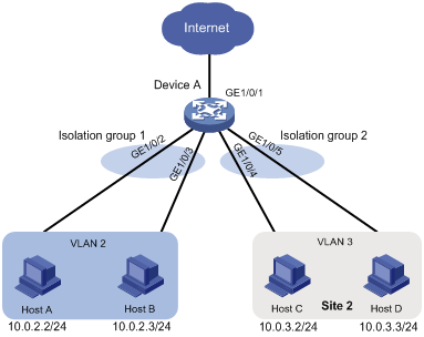
Network configuration
As shown in Figure 1, the company branches Site 1 and Site 2 transfer service traffic in VLAN 2 and VLAN 3. Device A connects to the Internet through GigabitEthernet 1/0/1.
Configure port isolation on Device A to meet the following requirements:
· All hosts can access the Internet through Device A.
· Host A and Host B are isolated from each other at Layer 2.
· Host C and Host D are isolated from each other at Layer 2.
Applicable hardware and software versions
The following matrix shows the hardware and software versions to which this configuration example is applicable:
|
Hardware |
Software version |
|
S6520XE-HI switch series |
Supported in Release 11xx |
|
S5560X-EI switch series |
Supported in Release 111x |
|
S5500V2-EI switch series |
Supported in Release 111x |
|
MS4520V2-30F switch |
Supported in Release 111x |
|
S5560S-EI switch series S5560S-SI switch series |
Supported in Release 612x |
|
S5130S-HI switch series S5130S-EI switch series S5130S-SI switch series S5130S-LI switch series |
Supported in Release 612x |
|
S5120V2-SI switch series S5120V2-LI switch series |
Supported in Release 612x |
|
S3100V3-EI switch series S3100V3-SI switch series |
Supported in Release 612x |
|
S5110V2 switch series |
Supported in Release 612x |
|
S5110V2-SI switch series |
Supported in Release 612x |
|
S5000V3-EI switch series |
Supported in Release 612x |
|
S5000E-X switch series |
Supported in Release 612x |
|
WAS6000 switch series |
Supported in Release 612x |
|
E128C switch E152C switch E500C switch series E500D switch series |
Supported in Release 612x |
|
MS4520V2 switch series (except the MS4520V2-30F switch) |
Supported in Release 612x |
|
MS4320V2 switch series MS4300V2 switch series MS4320 switch series MS4200 switch series |
Supported in Release 612x |
|
WS5850-WiNet switch series |
Supported in Release 612x |
|
WS5820-WiNet switch series WS5810-WiNet switch series |
Supported in Release 612x |
Restrictions and guidelines
When you configure port isolation on the device, follow these restrictions and guidelines:
· Before assigning a port to an isolation group, make sure the isolation group already exists.
· You can assign a port to only one isolation group.
Procedures
# Create VLAN 2 and assign ports GigabitEthernet 1/0/2 and GigabitEthernet 1/0/3 to the VLAN.
<DeviceA> system-view
[DeviceA] vlan 2
[DeviceA-vlan2] port gigabitethernet 1/0/2
[DeviceA-vlan2] port gigabitethernet 1/0/3
[DeviceA-vlan2] quit
# Create VLAN 3 and assign ports GigabitEthernet 1/0/4 and GigabitEthernet 1/0/5 to the VLAN.
[DeviceA] vlan 3
[DeviceA-vlan3] port gigabitethernet 1/0/4
[DeviceA-vlan3] port gigabitethernet 1/0/5
[DeviceA-vlan3] quit
# Configure port GigabitEthernet 1/0/1 as a trunk port and assign it to VLAN 2 and VLAN 3.
[DeviceA] interface gigabitethernet 1/0/1
[DeviceA-GigabitEthernet1/0/1] port link-type trunk
[DeviceA-GigabitEthernet1/0/1] port trunk permit vlan 2 3
[DeviceA-GigabitEthernet1/0/1] quit
# Create isolation groups 1 and 2.
[DeviceA] port-isolate group 1
[DeviceA] port-isolate group 2
# Assign ports GigabitEthernet 1/0/2 and GigabitEthernet 1/0/3 to isolation group 1.
[DeviceA] interface gigabitethernet 1/0/2
[DeviceA-GigabitEthernet1/0/2] port-isolate enable group 1
[DeviceA-GigabitEthernet1/0/2] quit
[DeviceA] interface gigabitethernet 1/0/3
[DeviceA-GigabitEthernet1/0/3] port-isolate enable group 1
[DeviceA-GigabitEthernet1/0/3] quit
# Assign ports GigabitEthernet 1/0/4 and GigabitEthernet 1/0/5 to isolation group 2.
[DeviceA] interface gigabitethernet 1/0/4
[DeviceA-GigabitEthernet1/0/4] port-isolate enable group 2
[DeviceA-GigabitEthernet1/0/4] quit
[DeviceA] interface gigabitethernet 1/0/5
[DeviceA-GigabitEthernet1/0/5] port-isolate enable group 2
[DeviceA-GigabitEthernet1/0/5] quit
Verifying the configuration
# Display information about all isolation groups.
[DeviceA] display port-isolate group
Port isolation group information:
Group ID: 1
Group members:
GigabitEthernet1/0/2
GigabitEthernet1/0/3
Group ID: 2
Group members:
GigabitEthernet1/0/4
GigabitEthernet1/0/5
The output shows that:
· Ports GigabitEthernet 1/0/2 and GigabitEthernet 1/0/3 are in isolation group 1. As a result, Host A and Host B are isolated from each other at Layer 2.
· Ports GigabitEthernet 1/0/4 and GigabitEthernet 1/0/4 are in isolation group 2. As a result, Host C and Host D are isolated from each other at Layer 2.
Configuration files
|
|
IMPORTANT: The port link-mode bridge command is available only on the following switches: · S6520XE-HI switch series. · S5560X-EI switch series. · S5500V2-EI switch series. · MS4520V2-30F switch. |
#
port-isolate group 1
port-isolate group 2
#
vlan 2 to 3
#
interface GigabitEthernet1/0/1
port link-mode bridge
port link-type trunk
port trunk permit vlan 1 to 3
#
interface GigabitEthernet1/0/2
port link-mode bridge
port access vlan 2
port-isolate enable group 1
#
interface GigabitEthernet1/0/3
port link-mode bridge
port access vlan 2
port-isolate enable group 1
#
interface GigabitEthernet1/0/4
port link-mode bridge
port access vlan 3
port-isolate enable group 2
#
interface GigabitEthernet1/0/5
port link-mode bridge
port access vlan 3
port-isolate enable group 2
#
