- Table of Contents
-
- H3C WX3000 Series Unified Switches Switching Engine Configuration Guide-6W103
- 00-Preface
- 01-CLI Configuration
- 02-Login Configuration
- 03-Configuration File Management Configuration
- 04-VLAN Configuration
- 05-Auto Detect Configuration
- 06-Voice VLAN Configuration
- 07-GVRP Configuration
- 08-Basic Port Configuration
- 09-Link Aggregation Configuration
- 10-Port Isolation Configuration
- 11-Port Security-Port Binding Configuration
- 12-DLDP Configuration
- 13-MAC Address Table Management Configuration
- 14-MSTP Configuration
- 15-802.1x and System Guard Configuration
- 16-AAA Configuration
- 17-MAC Address Authentication Configuration
- 18-IP Address and Performance Configuration
- 19-DHCP Configuration
- 20-ACL Configuration
- 21-QoS-QoS Profile Configuration
- 22-Mirroring Configuration
- 23-ARP Configuration
- 24-SNMP-RMON Configuration
- 25-Multicast Configuration
- 26-NTP Configuration
- 27-SSH Configuration
- 28-File System Management Configuration
- 29-FTP-SFTP-TFTP Configuration
- 30-Information Center Configuration
- 31-System Maintenance and Debugging Configuration
- 32-VLAN-VPN Configuration
- 33-HWPing Configuration
- 34-DNS Configuration
- 35-Smart Link-Monitor Link Configuration
- 36-PoE-PoE Profile Configuration
- 37-Routing Protocol Configuration
- 38-UDP Helper Configuration
- 39-Acronyms
- 40-Index
- Related Documents
-
| Title | Size | Download |
|---|---|---|
| 26-NTP Configuration | 213.74 KB |
Implementation Principle of NTP
Configuring NTP Implementation Modes
Configuring NTP Server/Client Mode
Configuring the NTP Symmetric Peer Mode
Configuring NTP Broadcast Mode
Configuring NTP Multicast Mode
Configuring Access Control Right
Configuring NTP Authentication
Configuring Optional NTP Parameters
Configuring an Interface on the Local Device to Send NTP Messages
Configuring the Number of Dynamic Sessions Allowed on the Local Device
Disabling an Interface from Receiving NTP messages
Displaying and Maintaining NTP Configuration
Configuring NTP Server/Client Mode
Configuring NTP Symmetric Peer Mode
Configuring NTP Broadcast Mode
Configuring NTP Multicast Mode
Configuring NTP Server/Client Mode with Authentication
1 NTP Configuration
When configuring NTP, go to these sections for information you are interested in:
l Configuring NTP Implementation Modes
l Configuring Access Control Right
l Configuring NTP Authentication
l Configuring Optional NTP Parameters
l Displaying and Maintaining NTP Configuration
![]()
l The term switch used throughout this document refers to a switching device in a generic sense or the switching engine of a WX3000 series.
l The sample output information in this manual was created on the WX3024. The output information on your device may vary.
Introduction to NTP
Network time protocol (NTP) is a time synchronization protocol defined in RFC 1305. It is used for time synchronization between a set of distributed time servers and clients. Carried over UDP, NTP transmits packets through UDP port 123.
NTP is intended for time synchronization between all devices that have clocks in a network so that the clocks of all devices can keep consistent. Thus, the devices can provide multiple unified-time-based applications (See Applications of NTP).
A local system running NTP can not only be synchronized by other clock sources, but also serve as a clock source to synchronize other clocks. Besides, it can synchronize, or be synchronized by other systems by exchanging NTP messages.
Applications of NTP
As setting the system time manually in a network with many devices leads to a lot of workload and cannot ensure accuracy, it is unfeasible for an administrator to perform the operation. However, an administrator can synchronize the clocks of devices in a network with required accuracy by performing NTP configuration.
NTP is mainly applied to synchronizing the clocks of all devices in a network. For example:
l In network management, the analysis of the log information and debugging information collected from different devices is meaningful and valid only when network devices that generate the information adopts the same time.
l The billing system requires that the clocks of all network devices be consistent.
l Some functions, such as restarting all network devices in a network simultaneously require that they adopt the same time.
l When multiple systems cooperate to handle a rather complex transaction, they must adopt the same time to ensure a correct execution order.
l To perform incremental backup operations between a backup server and a host, you must make sure they adopt the same time.
NTP has the following advantages:
l Defining the accuracy of clocks by stratum to synchronize the clocks of all devices in a network quickly
l Supporting access control (See Configuring Access Control Right) and MD5 encrypted authentication (See Configuring NTP Authentication)
l Sending protocol packets in unicast, multicast, or broadcast mode
![]()
l The clock stratum determines the accuracy, which ranges from 1 to 16. The stratum of a reference clock ranges from 1 to 15. The clock accuracy decreases as the stratum number increases. A stratum 16 clock is in the unsynchronized state and cannot serve as a reference clock.
l The local clock of the device cannot be set as a reference clock. It can serve as a reference clock source to synchronize the clock of other devices only after it is synchronized.
Implementation Principle of NTP
Figure 1-1 shows the implementation principle of NTP.
Device A is connected to Device B through Ethernet ports. Both having their own system clocks, they need to synchronize the clocks of each other through NTP. To help you to understand the implementation principle, we suppose that:
l Before the system clocks of Device A and Device B are synchronized, the clock of Device A is set to 10:00:00 am, and the clock of Device B is set to 11:00:00 am.
l Device B serves as the NTP server, that is, the clock of Device A will be synchronized to that of Device B.
l It takes one second to transfer an NTP message from Device A to Device B or from Device B to Device A.
Figure 1-1 Implementation principle of NTP
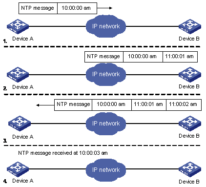
The procedure of synchronizing the system clock is as follows:
l Device A sends an NTP message to Device B, with a timestamp 10:00:00 am (T1) identifying when it is sent.
l When the message arrives at Device B, Device B inserts its own timestamp 11:00:01 am (T2) into the packet.
l When the NTP message leaves Device B, Device B inserts its own timestamp 11:00:02 am (T3) into the packet.
l When receiving a response packet, Device A inserts a new timestamp 10:00:03 am (T4) into it.
At this time, Device A has enough information to calculate the following two parameters:
l Delay for an NTP message to make a round trip between Device A and Device B:
Delay = (T4 -T1)-(T3 -T2).
l Time offset of Device A relative to Device B:
Offset = ((T2 -T1) + (T3 -T4))/2.
Device A can then set its own clock according to the above information to synchronize its clock to that of Device B.
For detailed information, refer to RFC 1305.
NTP Implementation Modes
According to the network structure and the position of the local device in the network, the local Ethernet device can work in multiple NTP modes to synchronize the clock.
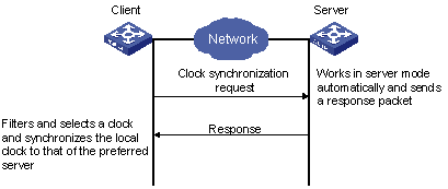
Server/client mode
Symmetric peer mode
Figure 1-3 Symmetric peer mode
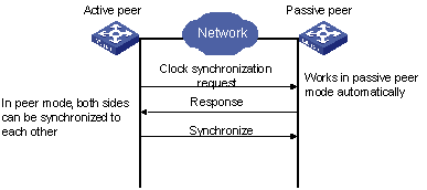
In the symmetric peer mode, the local device serves as the symmetric-active peer and sends clock synchronization request first, while the remote server serves as the symmetric-passive peer automatically.
If both of the peers have reference clocks, the one with a smaller stratum number is adopted.
Broadcast mode

Multicast mode
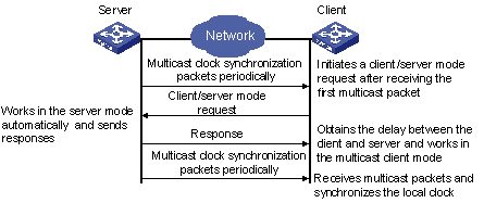
Table 1-1 describes how the above mentioned NTP modes are implemented on the device.
Table 1-1 NTP implementation modes on the device
|
NTP implementation mode |
Configuration on the device |
|
Server/client mode |
Configure the local device to work in the NTP client mode. In this mode, the remote server serves as the local time server, while the local device serves as the client. |
|
Symmetric peer mode |
Configure the local device to work in NTP symmetric peer mode. In this mode, the remote server serves as the symmetric-passive peer of the device, and the local device serves as the symmetric-active peer. |
|
Broadcast mode |
l Configure the local device to work in NTP broadcast server mode. In this mode, the local device broadcasts NTP messages through the VLAN interface configured on the device. l Configure the device to work in NTP broadcast client mode. In this mode, the local device receives broadcast NTP messages through the VLAN interface configured on the device. |
|
Multicast mode |
l Configure the local device to work in NTP multicast server mode. In this mode, the local device sends multicast NTP messages through the VLAN interface configured on the device. l Configure the local device to work in NTP multicast client mode. In this mode, the local device receives multicast NTP messages through the VLAN interface configured on the device. |
![]()
l When the device works in server mode or symmetric passive mode, you need not to perform related configurations on this device but do that on the client or the symmetric-active peer.
l The NTP server mode, NTP broadcast mode, or NTP multicast mode takes effect only after the local clock of the device has been synchronized.
l When symmetric peer mode is configured on two devices, to synchronize the clock of the two devices, make sure at least one device’s clock has been synchronized.
NTP Configuration Task List
Complete the following tasks to configure NTP:
|
Task |
Remarks |
|
Required |
|
|
Optional |
|
|
Optional |
|
|
Optional |
|
|
Optional |
Configuring NTP Implementation Modes
The device can work in one of the following NTP modes:
l Configuring NTP Server/Client Mode
l Configuring the NTP Symmetric Peer Mode
l Configuring NTP Broadcast Mode
l Configuring NTP Multicast Mode
![]()
To protect unused sockets against attacks by malicious users and improve security, the device provides the following functions:
l UDP port 123 is opened only when the NTP feature is enabled.
l UDP port 123 is closed as the NTP feature is disabled.
These functions are implemented as follows:
l Execution of one of the ntp-service unicast-server, ntp-service unicast-peer, ntp-service broadcast-client, ntp-service broadcast-server, ntp-service multicast-client, and ntp-service multicast-server commands enables the NTP feature and opens UDP port 123 at the same time.
l Execution of the undo form of one of the above six commands disables all implementation modes of the NTP feature and closes UDP port 123 at the same time.
Configuring NTP Server/Client Mode
For devices working in the server/client mode, you only need to perform configurations on the clients, and not on the servers.
Follow these steps to configure an NTP client:
|
To do… |
Use the command… |
Remarks |
|
Enter system view |
system-view |
— |
|
Configure an NTP client |
ntp-service unicast-server { remote-ip | server-name } [ authentication-keyid key-id | priority | source-interface Vlan-interface vlan-id | version number ]* |
Required By default, the device is not configured to work in the NTP client mode. |
![]()
l The remote server specified by remote-ip or server-name serves as the NTP server, and the local device serves as the NTP client. The clock of the NTP client will be synchronized by but will not synchronize that of the NTP server.
l remote-ip cannot be a broadcast address, a multicast address or the IP address of the local clock.
l After you specify an interface for sending NTP messages through the source-interface keyword, the source IP address of the NTP message will be configured as the primary IP address of the specified interface.
l The device can act as a server to synchronize the clock of other devices only after its clock has been synchronized. If the clock of a server has a stratum level lower than or equal to that of a client’s clock, the client will not synchronize its clock to the server’s.
l You can configure multiple servers by repeating the ntp-service unicast-server command. The client will choose the optimal reference source.
Configuring the NTP Symmetric Peer Mode
For devices working in the symmetric peer mode, you need to specify a symmetric-passive peer on the symmetric-active peer.
Follow these steps to configure a symmetric-active switch:
|
To do… |
Use the command… |
Remarks |
|
Enter system view |
system-view |
— |
|
Specify a symmetric-passive peer for the device |
ntp-service unicast-peer { remote-ip | peer-name } [ authentication-keyid key-id | priority | source-interface Vlan-interface vlan-id | version number ]* |
Required By default, the device is not configured to work in the symmetric mode. |
![]()
l In the symmetric peer mode, you need to execute the related NTP configuration commands (refer to Configuring NTP Implementation Modes for details) to enable NTP on a symmetric-passive peer; otherwise, the symmetric-passive peer will not process NTP messages from the symmetric-active peer.
l The remote device specified by remote-ip or peer-name serves as the peer of the local device, and the local device works in the symmetric-active mode. In this case, the clock of the local device and that of the remote device can be synchronized to each other.
l remote-ip must not be a broadcast address, a multicast address or the IP address of the local clock.
l After you specify an interface for sending NTP messages through the source-interface keyword, the source IP address of the NTP message will be configured as the IP address of the specified interface.
l Typically, the clock of at least one of the symmetric-active and symmetric-passive peers should be synchronized first; otherwise the clock synchronization will not proceed.
l You can configure multiple symmetric-passive peers for the local device by repeating the ntp-service unicast-peer command. The clock of the peer with the smallest stratum will be chosen to synchronize with the local clock of the device.
Configuring NTP Broadcast Mode
For devices working in the broadcast mode, you need to configure both the server and clients. The broadcast server periodically sends NTP broadcast messages to the broadcast address 255.255.255.255. The devices working in the NTP broadcast client mode will respond to the NTP messages, so as to start the clock synchronization.
The device can work as a broadcast server or a broadcast client.
![]()
A broadcast server can synchronize broadcast clients only after its clock has been synchronized.
Configuring the device to work in the NTP broadcast server mode
|
To do… |
Use the command… |
Remarks |
|
Enter system view |
system-view |
— |
|
Enter VLAN interface view |
interface Vlan-interface vlan-id |
— |
|
Configure the device to work in the NTP broadcast server mode |
ntp-service broadcast-server [ authentication-keyid key-id | version number ]* |
Required Not configured by default. |
Configuring the device to work in the NTP broadcast client mode
|
To do… |
Use the command… |
Remarks |
|
Enter system view |
system-view |
— |
|
Enter VLAN interface view |
interface Vlan-interface vlan-id |
— |
|
Configure the device to work in the NTP broadcast client mode |
ntp-service broadcast-client |
Required Not configured by default. |
Configuring NTP Multicast Mode
For devices working in the multicast mode, you need to configure both the server and clients. The multicast server periodically sends NTP multicast messages to multicast clients. The devices working in the NTP multicast client mode will respond to the NTP messages, so as to start the clock synchronization.
The device can work as a multicast server or a multicast client.
![]()
l A multicast server can synchronize multicast clients only after its clock has been synchronized.
l The device working in the multicast server mode supports up to 1,024 multicast clients.
Configuring the device to work in the multicast server mode
|
To do… |
Use the command… |
Remarks |
|
Enter system view |
system-view |
— |
|
Enter VLAN interface view |
interface Vlan-interface vlan-id |
— |
|
Configure the device to work in the NTP multicast server mode |
ntp-service multicast-server [ ip-address ] [ authentication-keyid keyid | ttl ttl-number | version number ]* |
Required Not configured by default. |
Configuring the device to work in the multicast client mode
|
To do… |
Use the command… |
Remarks |
|
Enter system view |
system-view |
— |
|
Enter VLAN interface view |
interface Vlan-interface vlan-id |
— |
|
Configure the device to work in the NTP multicast client mode |
ntp-service multicast-client [ ip-address ] |
Required Not configured by default. |
Configuring Access Control Right
With the following command, you can configure the NTP service access-control right to the local device for a peer device. There are four access-control rights, as follows:
l query: Control query right. This level of right permits the peer device to perform control query to the NTP service on the local device but does not permit the peer device to synchronize its clock to the local device. The so-called “control query” refers to query of state of the NTP service, including alarm information, authentication status, clock source information, and so on.
l synchronization: Synchronization right. This level of right permits the peer device to synchronize its clock to the local device but does not permit the peer device to perform control query.
l server: Server right. This level of right permits the peer device to perform synchronization and control query to the local device but does not permit the local device to synchronize its clock to the peer device.
l peer: Peer access. This level of right permits the peer device to perform synchronization and control query to the local device and also permits the local device to synchronize its clock to the peer device.
From the highest NTP service access-control right to the lowest one are peer, server, synchronization, and query. When a device receives an NTP request, it will perform an access-control right match in this order and use the first matched right.
Configuration Prerequisites
Prior to configuring the NTP service access-control right to the local device for peer devices, you need to create and configure an ACL associated with the access-control right. For the configuration of ACL, refer to ACL in H3C WX3000 Series Unified Switches Switching Engine Configuration Guide.
Configuration Procedure
|
To do… |
Use the command… |
Remarks |
|
Enter system view |
system-view |
— |
|
Configure the NTP service access-control right to the local device for peer devices |
ntp-service access { peer | server | synchronization | query } acl-number |
Optional peer by default |
![]()
Configuring NTP Authentication
In networks with higher security requirements, the NTP authentication function must be enabled to run NTP. Through password authentication on the client and the server, the clock of the client is synchronized only to that of the server that passes the authentication. This improves network security. Table 1-2 shows the roles of devices in the NTP authentication function.
Table 1-2 Description on the roles of devices in NTP authentication function
|
Role of device |
Working mode |
|
Client |
Client in the server/client mode |
|
Client in the broadcast mode |
|
|
Client in the multicast mode |
|
|
Symmetric-active peer in the symmetric peer mode |
|
|
Server |
Server in the server/client mode |
|
Server in the broadcast mode |
|
|
Server in the multicast mode |
|
|
Symmetric-passive peer in the symmetric peer mode |
Configuration Prerequisites
NTP authentication configuration involves:
l Configuring NTP authentication on the client
l Configuring NTP authentication on the server
Observe the following principles when configuring NTP authentication:
l If the NTP authentication function is not enabled on the client, the clock of the client can be synchronized to a server no matter whether the NTP authentication function is enabled on the server (assuming that other related configurations are properly performed).
l For the NTP authentication function to take effect, a trusted key needs to be configured on both the client and server after the NTP authentication is enabled on them.
l The local clock of the client is only synchronized to the server that provides a trusted key.
l In addition, for the server/client mode and the symmetric peer mode, you need to associate a specific key on the client (the symmetric-active peer in the symmetric peer mode) with the corresponding NTP server (the symmetric-passive peer in the symmetric peer mode); for the NTP broadcast/multicast mode, you need to associate a specific key on the broadcast/multicast server with the corresponding NTP broadcast/multicast client. Otherwise, NTP authentication cannot be enabled normally.
l Configurations on the server and the client must be consistent.
Configuration Procedure
Configuring NTP authentication on the client
Follow these steps to configure NTP authentication on the client:
|
To do… |
Use the command… |
Remarks |
|
|
Enter system view |
system-view |
— |
|
|
Enable the NTP authentication function |
ntp-service authentication enable |
Required Disabled by default. |
|
|
Configure the NTP authentication key |
ntp-service authentication-keyid key-id authentication-model md5 value |
Required By default, no NTP authentication key is configured. |
|
|
Configure the specified key as a trusted key |
ntp-service reliable authentication-keyid key-id |
Required By default, no trusted key is configured. |
|
|
Associate the specified key with the corresponding NTP server |
Configure on the client in the server/client mode |
ntp-service unicast-server { remote-ip | server-name } authentication-keyid key-id |
Required For the client in the NTP broadcast/multicast mode, you just need to associate the specified key with the client on the corresponding server. |
|
Configure on the symmetric-active peer in the symmetric peer mode |
ntp-service unicast-peer { remote-ip | peer-name } authentication-keyid key-id |
||
![]()
l NTP authentication requires that the authentication keys configured for the server and the client be the same. Besides, the authentication keys must be trusted keys. Otherwise, the clock of the client cannot be synchronized with that of the server.
l In NTP server mode and NTP peer mode, you need to associate the specified key with the corresponding NTP server (symmetric-active peer) on the client (symmetric-passive peer). In these two modes, multiple NTP servers (symmetric-active peers) may be configured for a client/passive peer, and therefore, the authentication key is required to determine which NTP server the local clock is synchronized to.
Configuring NTP authentication on the server
Follow these steps to configure NTP authentication on the server:
|
To do… |
Use the command… |
Remarks |
|
|
Enter system view |
system-view |
— |
|
|
Enable NTP authentication |
ntp-service authentication enable |
Required Disabled by default. |
|
|
Configure an NTP authentication key |
ntp-service authentication-keyid key-id authentication-mode md5 value |
Required By default, no NTP authentication key is configured. |
|
|
Configure the specified key as a trusted key |
ntp-service reliable authentication-keyid key-id |
Required By default, no trusted authentication key is configured. |
|
|
Enter VLAN interface view |
interface Vlan-interface vlan-id |
— |
|
|
Associate the specified key with the corresponding broadcast/multicast client |
Configure on the NTP broadcast server |
ntp-service broadcast-server authentication-keyid key-id |
l In NTP broadcast server mode and NTP multicast server mode, you need to associate the specified key with the corresponding broadcast/multicast client l You can associate an NTP broadcast/multicast client with an authentication key while configuring NTP mode. You can also use this command to associate them after configuring the NTP mode. |
|
Configure on the NTP multicast server |
ntp-service multicast-server authentication-keyid key-id |
||
![]()
The procedure for configuring NTP authentication on the server is the same as that on the client. Besides, the client and the server must be configured with the same authentication key.
Configuring Optional NTP Parameters
Complete the following tasks to configure optional NTP parameters:
|
Task |
Remarks |
|
Configuring an Interface on the Local Device to Send NTP Messages |
Optional |
|
Configuring the Number of Dynamic Sessions Allowed on the Local Device |
Optional |
|
Optional |
Configuring an Interface on the Local Device to Send NTP Messages
Follow these steps to configure an interface on the local device to send NTP messages:
|
To do… |
Use the command… |
Remarks |
|
Enter system view |
system-view |
— |
|
Configure an interface on the local device to send NTP messages |
ntp-service source-interface Vlan-interface vlan-id |
Required |
![]()
If you have specified an interface in the ntp-service unicast-server or ntp-service unicast-peer command, this interface will be used for sending NTP messages.
Configuring the Number of Dynamic Sessions Allowed on the Local Device
Follow these steps to configure the number of dynamic sessions allowed on the local device:
|
To do… |
Use the command… |
Remarks |
|
Enter system view |
system-view |
— |
|
Configure the maximum number of dynamic sessions that can be established on the local device |
ntp-service max-dynamic-sessions number |
Required By default, up to 100 dynamic sessions can be established locally. |
Disabling an Interface from Receiving NTP messages
Follow these steps to disable an interface from receiving NTP messages:
|
To do… |
Use the command… |
Remarks |
|
Enter system view |
system-view |
— |
|
Enter VLAN interface view |
interface Vlan-interface vlan-id |
— |
|
Disable an interface from receiving NTP messages |
ntp-service in-interface disable |
Required By default, a VLAN interface receives NTP messages. |
Displaying and Maintaining NTP Configuration
|
To do… |
Use the command… |
Remarks |
|
Display the status of NTP services |
display ntp-service status |
Available in any view |
|
Display the information about the sessions maintained by NTP |
display ntp-service sessions [ verbose ] |
|
|
Display the brief information about NTP servers along the path from the local device to the reference clock source |
display ntp-service trace |
NTP Configuration Examples
Configuring NTP Server/Client Mode
Network requirements
l As shown in Figure 1-6, the local clock of Device A is to be used as a master clock, with the stratum level of 2.
l Device A is used as the NTP server of Device B (a WX3000 series device)
l Configure Device B to work in the client mode, and then Device A will automatically work in the server mode.
Figure 1-6 Network diagram for the NTP server/client mode configuration

Configuration procedure
Perform the following configurations on Device B.
# View the NTP status of Device B before synchronization.
<DeviceB> display ntp-service status
Clock status: unsynchronized
Clock stratum: 16
Reference clock ID: none
Nominal frequency: 60.0002 Hz
Actual frequency: 60.0002 Hz
Clock precision: 2^18
Clock offset: 0.0000 ms
Root delay: 0.00 ms
Root dispersion: 0.00 ms
Peer dispersion: 0.00 ms
Reference time: 00:00:00.000 UTC Jan 1 1900 (00000000.00000000)
# Set Device A as the NTP server of Device B.
<DeviceB> system-view
[DeviceB] ntp-service unicast-server 1.0.1.11
# (After the above configurations, Device B is synchronized to Device A.) View the NTP status of Device B.
[DeviceB] display ntp-service status
Clock status: synchronized
Clock stratum: 3
Reference clock ID: 1.0.1.11
Nominal frequency: 60.0002 Hz
Actual frequency: 60.0002 Hz
Clock precision: 2^18
Clock offset: 0.66 ms
Root delay: 27.47 ms
Root dispersion: 208.39 ms
Peer dispersion: 9.63 ms
Reference time: 17:03:32.022 UTC Thu Sep 7 2006 (BF422AE4.05AEA86C)
The above output information indicates that Device B is synchronized to Device A, and the stratum level of its clock is 3, one level lower than that of Device A.
# View the information about NTP sessions of Device B. (You can see that Device B establishes a connection with Device A.)
[DeviceB] display ntp-service sessions
source reference stra reach poll now offset delay disper
**************************************************************************
[12345]1.0.1.11 127.127.1.0 2 1 64 1 350.1 15.1 0.0
note: 1 source(master),2 source(peer),3 selected,4 candidate,5 configured Total associations : 1
Configuring NTP Symmetric Peer Mode
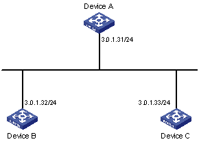
Network requirements
l As shown in Figure 1-7, the local clock of Device A is set as the NTP master clock, with the clock stratum level of 2.
l Device C (a WX3000 series device) uses Device A as the NTP server, and Device A works in server mode automatically.
l The local clock of Device B is set as the NTP master clock, with the clock stratum level of 1. Set Device C as the peer of Device B.
Figure 1-7 Network diagram for NTP peer mode configuration
Configuration procedure
1) Configure Device C.
# Set Device A as the NTP server.
<DeviceC> system-view
[DeviceC] ntp-service unicast-server 3.0.1.31
2) Configure Device B (after the Device C is synchronized to Device A).
# Enter system view.
<DeviceB> system-view
# Set Device C as the peer of Device B.
[DeviceB] ntp-service unicast-peer 3.0.1.33
Device C and Device B are symmetric peers after the above configuration. Device B works in symmetric active mode, while Device C works in symmetric passive mode. Because the stratum level of the local clock of Device B is 1, and that of Device C is 3, the clock of Device C is synchronized to that of Device B.
View the status of Device C after the clock synchronization.
[DeviceC] display ntp-service status
Clock status: synchronized
Clock stratum: 2
Reference clock ID: 3.0.1.32
Nominal frequency: 60.0002 Hz
Actual frequency: 60.0002 Hz
Clock precision: 2^18
Clock offset: 0.66 ms
Root delay: 27.47 ms
Root dispersion: 208.39 ms
Peer dispersion: 9.63 ms
Reference time: 17:03:32.022 UTC Thu Sep 7 2006 (BF422AE4.05AEA86C)
The output information indicates that the clock of Device C is synchronized to that of Device B and the stratum level of its local clock is 2, one level lower than Device B.
# View the information about the NTP sessions of Device C (you can see that a connection is established between Device C and Device B).
[DeviceC] display ntp-service sessions
source reference stra reach poll now offset delay disper
*************************************************************************
[1234]3.0.1.32 LOCL 1 95 64 42 -14.3 12.9 2.7
[25]3.0.1.31 127.127.1.0 2 1 64 1 4408.6 38.7 0.0
note: 1 source(master),2 source(peer),3 selected,4 candidate,5 configured
Total associations : 2
Configuring NTP Broadcast Mode
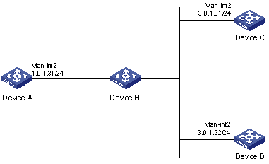
Network requirements
l As shown in Figure 1-8, the local clock of Device C is set as the NTP master clock, with a stratum level of 2. Configure Device C to work in the NTP broadcast server mode and send NTP broadcast messages through Vlan-interface2.
l Device A and Device D are two WX3000 series devices. Configure Device A and Device D to work in the NTP broadcast client mode and listen to broadcast messages through their own Vlan-interface2.
Figure 1-8 Network diagram for the NTP broadcast mode configuration
Configuration procedure
1) Configure Device C.
# Enter system view.
<DeviceC> system-view
# Set Device C as the broadcast server, which sends broadcast messages through Vlan-interface2.
[DeviceC] interface Vlan-interface 2
[DeviceC-Vlan-interface2] ntp-service broadcast-server
2) Configure Device A. (perform the same configuration on Device D)
# Enter system view.
<DeviceA> system-view
# Set Device A as a broadcast client.
[DeviceA] interface Vlan-interface 2
[DeviceA-Vlan-interface2] ntp-service broadcast-client
After the above configurations, Device A and Device D will listen to broadcast messages through their own Vlan-interface2, and Device C will send broadcast messages through Vlan-interface2. Because Device A and Device C do not share the same network segment, Device A cannot receive broadcast messages from Device C, while Device D is synchronized to Device C after receiving broadcast messages from Device C.
View the NTP status of Device D after the clock synchronization.
[DeviceD] display ntp-service status
Clock status: synchronized
Clock stratum: 3
Reference clock ID: 3.0.1.31
Nominal frequency: 60.0002 Hz
Actual frequency: 60.0002 Hz
Clock precision: 2^18
Clock offset: 198.7425 ms
Root delay: 27.47 ms
Root dispersion: 208.39 ms
Peer dispersion: 9.63 ms
Reference time: 17:03:32.022 UTC Thu Sep 7 2006 (BF422AE4.05AEA86C)
The output information indicates that Device D is synchronized to Device C, with the clock stratum level of 3, one level lower than that of Device C.
# View the information about the NTP sessions of Device D and you can see that a connection is established between Device D and Device C.
[DeviceD] display ntp-service sessions
source reference stra reach poll now offset delay disper
**************************************************************************
[1234]3.0.1.31 127.127.1.0 2 1 64 377 26.1 199.53 9.7
note: 1 source(master),2 source(peer),3 selected,4 candidate,5 configured Total associations : 1
Configuring NTP Multicast Mode
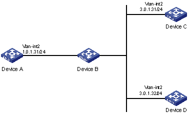
Network requirements
l As shown in Figure 1-9, the local clock of Device C is set as the NTP master clock, with a clock stratum level of 2. Configure Device C to work in the NTP multicast server mode and advertise multicast NTP messages through Vlan-interface2.
l Device A and Device D are two WX3000 series devices. Configure Device A and Device D to work in the NTP multicast client mode and listen to multicast messages through their own Vlan-interface2.
Figure 1-9 Network diagram for NTP multicast mode configuration
Configuration procedure
1) Configure Device C.
# Enter system view.
<DeviceC> system-view
# Set Device C as a multicast server to send multicast messages through Vlan-interface2.
[DeviceC] interface Vlan-interface 2
[DeviceC-Vlan-interface2] ntp-service multicast-server
2) Configure Device A (perform the same configuration on Device D).
# Enter system view.
<DeviceA> system-view
# Set Device A as a multicast client to listen to multicast messages through Vlan-interface2.
[DeviceA] interface Vlan-interface 2
[DeviceA-Vlan-interface2] ntp-service multicast-client
After the above configurations, Device A and Device D respectively listen to multicast messages through their own Vlan-interface2, and Device C advertises multicast messages through Vlan-interface2. Because Device A and Device C do not share the same network segment, Device A cannot receive multicast messages from Device C, while Device D is synchronized to Device C after receiving multicast messages from Device C.
View the NTP status of Device D after the clock synchronization.
[DeviceD] display ntp-service status
Clock status: synchronized
Clock stratum: 3
Reference clock ID: 3.0.1.31
Nominal frequency: 60.0002 Hz
Actual frequency: 60.0002 Hz
Clock precision: 2^18
Clock offset: 198.7425 ms
Root delay: 27.47 ms
Root dispersion: 208.39 ms
Peer dispersion: 9.63 ms
Reference time: 17:03:32.022 UTC Thu Sep 7 2006 (BF422AE4.05AEA86C)
The output information indicates that Device D is synchronized to Device C, with a clock stratum level of 3, one stratum level lower than that Device C.
# View the information about the NTP sessions of Device D (You can see that a connection is established between Device D and Device C).
[DeviceD] display ntp-service sessions
source reference stra reach poll now offset delay disper
**************************************************************************
[1234]3.0.1.31 127.127.1.0 2 1 64 377 26.1 199.53 9.7
note: 1 source(master),2 source(peer),3 selected,4 candidate,5 configured Total associations : 1
Configuring NTP Server/Client Mode with Authentication
Network requirements
l As shown in Figure 1-10, the local clock of Device A is set as the NTP master clock, with a clock stratum level of 2.
l Device B is a WX3000 series device and uses Device A as the NTP server. Device B is set to work in client mode, while Device A works in server mode automatically.
l The NTP authentication function is enabled on Device A and Device B.
Figure 1-10 Network diagram for NTP server/client mode with authentication configuration
Configuration procedure
1) Configure Device B.
# Enter system view.
<DeviceB> system-view
# Set Device A as the NTP server.
[DeviceB] ntp-service unicast-server 1.0.1.11
# Enable the NTP authentication function.
[DeviceB] ntp-service authentication enable
# Configure an MD5 authentication key, with the key ID being 42 and the key being aNiceKey.
[DeviceB] ntp-service authentication-keyid 42 authentication-mode md5 aNiceKey
# Specify the key 42 as a trusted key.
[DeviceB] ntp-service reliable authentication-keyid 42
[DeviceB] ntp-service unicast-server 1.0.1.11 authentication-keyid 42
After the above configurations, Device B is ready to synchronize with Device A. Because the NTP authentication function is not enabled on Device A, the clock of Device B will fail to be synchronized to that of Device A.
2) To synchronize Device B, you need to perform the following configurations on Device A.
# Enable the NTP authentication function.
[DeviceA] system-view
[DeviceA] ntp-service authentication enable
# Configure an MD5 authentication key, with the key ID being 42 and the key being aNiceKey.
[DeviceA] ntp-service authentication-keyid 42 authentication-mode md5 aNiceKey
# Specify the key 42 as a trusted key.
[DeviceA] ntp-service reliable authentication-keyid 42
(After the above configurations, the clock of Device B can be synchronized to that of Device A.) View the status of Device B after synchronization.
[DeviceB] display ntp-service status
Clock status: synchronized
Clock stratum: 3
Reference clock ID: 1.0.1.11
Nominal frequency: 60.0002 Hz
Actual frequency: 60.0002 Hz
Clock precision: 2^18
Clock offset: 0.66 ms
Root delay: 27.47 ms
Root dispersion: 208.39 ms
Peer dispersion: 9.63 ms
Reference time: 17:03:32.022 UTC Thu Sep 7 2006 (BF422AE4.05AEA86C)
The output information indicates that the clock of Device B is synchronized to that of Device A, with a clock stratum level of 3, one stratum level lower than that Device A.
# View the information about NTP sessions of Device B (You can see that a connection is established between Device B and Device A).
<DeviceB> display ntp-service sessions
source reference stra reach poll now offset delay disper
************************************************************************* [12345] 1.0.1.11 127.127.1.0 2 255 64 8 2.8 17.7 1.2
note: 1 source(master),2 source(peer),3 selected,4 candidate,5 configured
Total associations : 1
