- Table of Contents
-
- H3C WX3000 Series Unified Switches Switching Engine Configuration Guide-6W103
- 00-Preface
- 01-CLI Configuration
- 02-Login Configuration
- 03-Configuration File Management Configuration
- 04-VLAN Configuration
- 05-Auto Detect Configuration
- 06-Voice VLAN Configuration
- 07-GVRP Configuration
- 08-Basic Port Configuration
- 09-Link Aggregation Configuration
- 10-Port Isolation Configuration
- 11-Port Security-Port Binding Configuration
- 12-DLDP Configuration
- 13-MAC Address Table Management Configuration
- 14-MSTP Configuration
- 15-802.1x and System Guard Configuration
- 16-AAA Configuration
- 17-MAC Address Authentication Configuration
- 18-IP Address and Performance Configuration
- 19-DHCP Configuration
- 20-ACL Configuration
- 21-QoS-QoS Profile Configuration
- 22-Mirroring Configuration
- 23-ARP Configuration
- 24-SNMP-RMON Configuration
- 25-Multicast Configuration
- 26-NTP Configuration
- 27-SSH Configuration
- 28-File System Management Configuration
- 29-FTP-SFTP-TFTP Configuration
- 30-Information Center Configuration
- 31-System Maintenance and Debugging Configuration
- 32-VLAN-VPN Configuration
- 33-HWPing Configuration
- 34-DNS Configuration
- 35-Smart Link-Monitor Link Configuration
- 36-PoE-PoE Profile Configuration
- 37-Routing Protocol Configuration
- 38-UDP Helper Configuration
- 39-Acronyms
- 40-Index
- Related Documents
-
| Title | Size | Download |
|---|---|---|
| 20-ACL Configuration | 172.85 KB |
Table of Contents
Ways to Apply an ACL on a Device
Types of ACLs Supported by Devices
Assigning an ACL to a Port Group
Displaying and Maintaining ACL
Examples for Upper-layer Software Referencing ACLs
Example for Controlling Telnet Login Users by Source IP
Example for Controlling Web Login Users by Source IP
Examples for Applying ACLs to Hardware
Basic ACL Configuration Example
Advanced ACL Configuration Example
Layer 2 ACL Configuration Example
Example for Applying an ACL to a VLAN
![]()
l The term switch used throughout this chapter refers to a switching device in a generic sense or the switching engine of a WX3000.
l The sample output information in this manual was created on the WX3024. The output information on your device may vary.
ACL Overview
As the network scale and network traffic are increasingly growing, security control and bandwidth assignment play a more and more important role in network management. Filtering data packets can prevent a network from being accessed by unauthorized users efficiently while controlling network traffic and saving network resources. Access control lists (ACL) are often used to filter packets with configured matching rules.
Upon receiving a packet, the device compares the packet with the rules of the ACL applied on the current port to permit or discard the packet.
The rules of an ACL can be referenced by other functions that need traffic classification, such as QoS.
ACLs classify packets using a series of conditions known as rules. The conditions can be based on source addresses, destination addresses and port numbers carried in the packets.
According to their application purposes, ACLs fall into the following four types.
l Basic ACL. Rules are created based on source IP addresses only.
l Advanced ACL. Rules are created based on the Layer 3 and Layer 4 information such as the source and destination IP addresses, type of the protocols carried by IP, protocol-specific features, and so on.
l Layer 2 ACL. Rules are created based on the Layer 2 information such as source and destination MAC addresses, VLAN priorities, type of Layer 2 protocol, and so on.
l User-defined ACL. An ACL of this type matches packets by comparing the strings retrieved from the packets with specified strings. It defines the byte it begins to perform “and” operation with the mask on the basis of packet headers.
ACL Matching Order
An ACL can contain multiple rules, each of which matches specific type of packets. So the order in which the rules of an ACL are matched needs to be determined.
The rules in an ACL can be matched in one of the following two ways:
l config: where rules in an ACL are matched in the order defined by the user.
l auto: where rules in an ACL are matched in the order determined by the system, namely the “depth-first” rule.
For depth-first rule, there are two cases:
Depth-first match order for rules of a basic ACL
1) Range of source IP address: The smaller the source IP address range (that is, the more the number of zeros in the wildcard mask), the higher the match priority.
2) Fragment keyword: A rule with the fragment keyword is prior to others.
3) If the above two conditions are identical, the earlier configured rule applies.
Depth-first match order for rules of an advanced ACL
1) Protocol range: A rule which has specified the types of the protocols carried by IP is prior to others.
2) Range of source IP address: The smaller the source IP address range (that is, the more the number of zeros in the wildcard mask), the higher the match priority.
3) Range of destination IP address. The smaller the destination IP address range (that is, the more the number of zeros in the wildcard mask), the higher the match priority.
4) Range of Layer 4 port number, that is, TCP/UDP port number. The smaller the range, the higher the match priority.
5) Number of parameters: the more the parameters, the higher the match priority.
If rule A and rule B are still the same after comparison in the above order, the weighting principles will be used in deciding their priority order. Each parameter is given a fixed weighting value. This weighting value and the value of the parameter itself will jointly decide the final matching order. Involved parameters with weighting values from high to low are icmp-type, established, dscp, tos, precedence, fragment. Comparison rules are listed below.
l The smaller the weighting value left, which is a fixed weighting value minus the weighting value of every parameter of the rule, the higher the match priority.
l If the types of parameter are the same for multiple rules, then the sum of parameters’ weighting values of a rule determines its priority. The smaller the sum, the higher the match priority.
Ways to Apply an ACL on a Device
Being applied to the hardware directly
In the device, an ACL can be directly applied to hardware for packet filtering and traffic classification. In this case, the rules in an ACL are matched in the order determined by the hardware instead of that defined in the ACL. For devices, the earlier the rule applies, the higher the match priority.
ACLs are directly applied to hardware when they are used for:
l Implementing QoS
l Filtering the packets to be forwarded
Being referenced by upper-level software
ACLs can also be used to filter and classify the packets to be processed by software. In this case, the rules in an ACL can be matched in one of the following two ways:
l config, where rules in an ACL are matched in the order defined by the user.
l auto, where the rules in an ACL are matched in the order determined by the system, namely the “depth-first” order.
When applying an ACL in this way, you can specify the order in which the rules in the ACL are matched. The match order cannot be modified once it is determined, unless you delete all the rules in the ACL and define the match order.
An ACL can be referenced by upper-layer software:
l Referenced by routing policies
l Used to control Telnet, SNMP and Web login users
![]()
l When an ACL is directly applied to hardware for packet filtering, the device will permit packets if the packets do not match the ACL.
l When an ACL is referenced by upper-layer software to control Telnet, SNMP and Web login users, the device will deny packets if the packets do not match the ACL.
Types of ACLs Supported by Devices
The devices support the following types of ACLs.
l Basic ACLs
l Advanced ACLs
l Layer 2 ACLs
ACLs defined on the devices can be applied to hardware directly or referenced by upper-layer software for packet filtering.
ACL Configuration
Configuring Time Range
Time ranges can be used to filter packets. You can specify a time range for each rule in an ACL. A time range-based ACL takes effect only in specified time ranges. Only after a time range is configured and the system time is within the time range, can an ACL rule take effect.
Two types of time ranges are available:
l Periodic time range, which recurs periodically on the day or days of the week.
l Absolute time range, which takes effect only in a period of time and does not recur.
![]()
An absolute time range on a device can be within the range 1970/1/1 00:00 to 2100/12/31 24:00.
Configuration Procedure
Follow these steps to configure a time range:
|
To do… |
Use the command… |
Remarks |
|
Enter system view |
system-view |
— |
|
Create a time range |
time-range time-name { start-time to end-time days-of-the-week [ from start-time start-date ] [ to end-time end-date ] | from start-time start-date [ to end-time end-date ] | to end-time end-date } |
Required |
Note that:
l If only a periodic time section is defined in a time range, the time range is active only when the system time is within the defined periodic time section. If multiple periodic time sections are defined in a time range, the time range is active only when the system time is within one of the periodic time sections.
l If only an absolute time section is defined in a time range, the time range is active only when the system time is within the defined absolute time section. If multiple absolute time sections are defined in a time range, the time range is active only when the system time is within one of the absolute time sections.
l If both a periodic time section and an absolute time section are defined in a time range, the time range is active only when the periodic time range and the absolute time range are both matched. Assume that a time range contains an absolute time section ranging from 00:00 January 1, 2004 to 23:59 December 31, 2004, and a periodic time section ranging from 12:00 to 14:00 on every Wednesday. This time range is active only when the system time is within the range from 12:00 to 14:00 on every Wednesday in 2004.
l If the start time is not specified, the time section starts from 1970/1/1 00:00 and ends on the specified end date. If the end date is not specified, the time section starts from the specified start date to 2100/12/31 23:59.
Configuration Example
# Define a periodic time range that spans from 8:00 to 18:00 on Monday through Friday.
<device> system-view
[device] time-range test 8:00 to 18:00 working-day
[device] display time-range test
Current time is 13:27:32 Apr/16/2005 Saturday
Time-range : test ( Inactive )
08:00 to 18:00 working-day
# Define an absolute time range spans from 15:00 1/28/2006 to 15:00 1/28/2008.
<device> system-view
[device] time-range test from 15:00 1/28/2006 to 15:00 1/28/2008
[device] display time-range test
Current time is 13:30:32 Apr/16/2005 Saturday
Time-range : test ( Inactive )
From 15:00 Jan/28/2000 to 15:00 Jan/28/2004
Configuring Basic ACL
A basic ACL filters packets based on their source IP addresses.
A basic ACL can be numbered from 2000 to 2999.
Configuration Prerequisites
l To configure a time range-based basic ACL rule, you need to create the corresponding time range first. For information about time range configuration, refer to Configuring Time Range.
l The source IP addresses based on which the ACL filters packets are determined.
Configuration Procedure
Follow these steps to define a basic ACL rule:
|
To do… |
Use the command… |
Remarks |
|
Enter system view |
system-view |
— |
|
Create an ACL and enter basic ACL view |
acl number acl-number [ match-order { auto | config } ] |
Required config by default |
|
Define an ACL rule |
rule [ rule-id ] { deny | permit } [ rule-string ] |
Required For information about rule-string, refer to ACL in H3C WX3000 Series Unified Switches Switching Engine Command Reference. |
|
Configure a description string to the ACL |
description text |
Optional Not configured by default |
Note that:
l With the config match order specified for the basic ACL, you can modify any existent rule. The unmodified part of the rule remains. With the auto match order specified for the basic ACL, you cannot modify any existent rule; otherwise the system prompts error information.
l If you do not specify the rule-id argument when creating an ACL rule, the rule will be numbered automatically. If the ACL has no rules, the rule is numbered 0; otherwise, it is the maximum rule number plus one.
l With the auto match order specified, the newly created rules will be inserted in the existent ones by depth-first principle, but the numbers of the existent rules are unaltered.
Configuration Example
# Configure ACL 2000 to deny packets whose source IP addresses are 192.168.0.1.
<device> system-view
[device] acl number 2000
[device-acl-basic-2000] rule deny source 192.168.0.1 0
# Display the configuration information of ACL 2000.
[device-acl-basic-2000] display acl 2000
Basic ACL 2000, 1 rule
Acl's step is 1
rule 0 deny source 192.168.0.1 0
Configuring Advanced ACL
An advanced ACL can filter packets by their source and destination IP addresses, the protocols carried by IP, and protocol-specific features such as TCP/UDP source and destination ports, ICMP message type and message code.
An advanced ACL can be numbered from 3000 to 3999. Note that ACL 3998 and ACL 3999 cannot be configured because they are reserved for cluster management.
Advanced ACLs support analysis and processing of three packet priority levels: type of service (ToS) priority, IP priority and differentiated services codepoint (DSCP) priority.
Using advanced ACLs, you can define classification rules that are more accurate, more abundant, and more flexible than those defined for basic ACLs.
Configuration Prerequisites
l To configure a time range-based advanced ACL rule, you need to create the corresponding time ranges first. For information about of time range configuration, refer to Configuring Time Range.
l The settings to be specified in the rule, such as source and destination IP addresses, the protocols carried by IP, and protocol-specific features, are determined.
Configuration Procedure
Follow these steps to define an advanced ACL rule:
|
To do… |
Use the command… |
Remarks |
|
Enter system view |
system-view |
— |
|
Create an advanced ACL and enter advanced ACL view |
acl number acl-number [ match-order { auto | config } ] |
Required config by default |
|
Define an ACL rule |
rule [ rule-id ] { permit | deny } protocol [ rule-string ] |
Required For information about protocol and rule-string, refer to ACL in H3C WX3000 Series Unified Switches Switching Engine Command Reference. |
|
Assign a description string to the ACL rule |
rule rule-id comment text |
Optional No description by default |
|
Assign a description string to the ACL |
description text |
Optional No description by default |
l If you do not specify the rule-id argument when creating an ACL rule, the rule will be numbered automatically. If the ACL has no rules, the rule is numbered 0; otherwise, it is the maximum rule number plus one.
l The content of a modified or created rule cannot be identical with the content of any existing rules; otherwise the rule modification or creation will fail, and the system prompts that the rule already exists.
l If the ACL is created with the auto keyword specified, the newly created rules will be inserted in the existent ones by depth-first principle, but the numbers of the existent rules are unaltered.
Configuration Example
# Configure ACL 3000 to permit the TCP packets sourced from the network 129.9.0.0/16 and destined for the network 202.38.160.0/24 and with the destination port number being 80.
<device> system-view
[device] acl number 3000
[device-acl-adv-3000] rule permit tcp source 129.9.0.0 0.0.255.255 destination 202.38.160.0 0.0.0.255 destination-port eq 80
# Display the configuration information of ACL 3000.
[device-acl-adv-3000] display acl 3000
Advanced ACL 3000, 1 rule
Acl's step is 1
rule 0 permit tcp source 129.9.0.0 0.0.255.255 destination 202.38.160.0 0.0.0.255 destination-port eq www
Configuring Layer 2 ACL
A Layer 2 ACL can be numbered from 4000 to 4999.
Configuration Prerequisites
l To configure a time range-based Layer 2 ACL rule, you need to create the corresponding time ranges first. For information about time range configuration, refer to Configuring Time Range.
Configuration Procedure
Follow these steps to define a Layer 2 ACL rule:
|
To do… |
Use the command… |
Remarks |
|
Enter system view |
system-view |
— |
|
Create a Layer 2 ACL and enter layer 2 ACL view |
acl number acl-number |
Required |
|
Define an ACL rule |
rule [ rule-id ] { permit | deny } rule-string |
Required For information about rule-string, refer to ACL in H3C WX3000 Series Unified Switches Switching Engine Command Reference. |
|
Assign a description string to the ACL rule |
rule rule-id comment text |
Optional No description by default |
|
Assign a description string to the ACL |
description text |
Optional No description by default |
Note that:
l You can modify any existent rule of the Layer 2 ACL and the unmodified part of the ACL remains.
l If you do not specify the rule-id argument when creating an ACL rule, the rule will be numbered automatically. If the ACL has no rules, the rule is numbered 0; otherwise, it is the maximum rule number plus one.
l The content of a modified or created rule cannot be identical with the content of any existing rules; otherwise the rule modification or creation will fail, and the system prompts that the rule already exists.
Configuration Example
# Configure ACL 4000 to deny packets sourced from the MAC address 000d-88f5-97ed, destined for the MAC address 0011-4301-991e, and with their 802.1p priority being 3.
<device> system-view
[device] acl number 4000
[device-acl-ethernetframe-4000] rule deny cos 3 source 000d-88f5-97ed ffff-ffff-ffff dest 0011-4301-991e ffff-ffff-ffff
# Display the configuration information of ACL 4000.
[device-acl-ethernetframe-4000] display acl 4000
Ethernet frame ACL 4000, 1 rule
Acl's step is 1
rule 0 deny cos excellent-effort source 000d-88f5-97ed ffff-ffff-ffff dest 0011-4301-991e ffff-ffff-ffff
ACL Assignment
On a device, you can assign ACLs to the hardware for packet filtering.
As for ACL assignment, the following four ways are available.
l Assigning ACLs globally, for filtering the inbound packets on all the ports.
l Assigning ACLs to a VLAN, for filtering the inbound packets on all the ports and belonging to a VLAN.
l Assigning ACLs to a port group, for filtering the inbound packets on all the ports in a port group. For information about port group, refer to Basic Port Configuration in H3C WX3000 Series Unified Switches Switching Engine Configuration Guide.
l Assigning ACLs to a port, for filtering the inbound packets on a port.
You can assign ACLs in the above-mentioned ways as required.
![]()
l ACLs assigned globally take precedence over those that are assigned to VLANs. That is, when a packet matches a rule of a globally assigned ACL and a rule of an ACL assigned to a VLAN, the device will perform the action defined in the rule of the globally assigned ACL if the actions defined in the two rules conflict.
l When a packet matches a rule of an ACL assigned globally (or assigned to a VLAN) and a rule of an ACL assigned to a port (or port group), the device will deny the packets if the actions defined in the two rules conflict.
l ACLs assigned globally or to a VLAN take precedence over the default ACL. However, assigning ACLs globally or to a VLAN may affect device management that is implemented through Telnet and so on.
Assigning an ACL Globally
Configuration prerequisites
Before applying ACL rules to a VLAN, you need to define the related ACLs. For information about defining an ACL, refer to Configuring Basic ACL, Configuring Advanced ACL, Configuring Layer 2 ACL.
Configure procedure
Follow these steps to assign an ACL globally:
|
To do… |
Use the command… |
Remarks |
|
Enter system view |
system-view |
— |
|
Assign an ACL globally |
packet-filter inbound acl-rule |
Required For description on the acl-rule argument, refer to ACL in H3C WX3000 Series Unified Switches Switching Engine Command Reference. |
Configuration example
# Apply ACL 2000 globally to filter the inbound packets on all the ports.
<device> system-view
[device] packet-filter inbound ip-group 2000
Assigning an ACL to a VLAN
Configuration prerequisites
Before applying ACL rules to a VLAN, you need to define the related ACLs. For information about defining an ACL, refer to Configuring Basic ACL, Configuring Advanced ACL, Configuring Layer 2 ACL.
Configuration procedure
Follow these steps to assign an ACL to a VLAN:
|
To do… |
Use the command… |
Remarks |
|
Enter system view |
system-view |
— |
|
Apply an ACL to a VLAN |
packet-filter vlan vlan-id inbound acl-rule |
Required For description on the acl-rule argument, refer to ACL in H3C WX3000 Series Unified Switches Switching Engine Command Reference. |
Configuration example
# Apply ACL 2000 to VLAN 10 to filter the inbound packets of VLAN 10 on all the ports.
<device> system-view
[device] packet-filter vlan 10 inbound ip-group 2000
Assigning an ACL to a Port Group
Configuration prerequisites
Before applying ACL rules to a VLAN, you need to define the related ACLs. For information about defining an ACL, refer to Configuring Basic ACL, Configuring Advanced ACL, Configuring Layer 2 ACL.
Configuration procedure
Follow these steps to assign an ACL to a port group:
|
To do… |
Use the command… |
Remarks |
|
Enter system view |
system-view |
— |
|
Enter port group view |
port-group group-id |
— |
|
Apply an ACL to the port group |
packet-filter inbound acl-rule |
Required For description on the acl-rule argument, refer to ACL in H3C WX3000 Series Unified Switches Switching Engine Command Reference. |
![]()
After an ACL is assigned to a port group, it will be automatically assigned to the ports that are subsequently added to the port group.
Configuration example
# Apply ACL 2000 to port group 1 to filter the inbound packets on all the ports in the port group.
<device> system-view
[device] port-group 1
[device-port-group-1] packet-filter inbound ip-group 2000
Assigning an ACL to a Port
Configuration prerequisites
Before applying ACL rules to a VLAN, you need to define the related ACLs. For information about defining an ACL, refer to Configuring Basic ACL, Configuring Advanced ACL, Configuring Layer 2 ACL.
Configuration procedure
Follow these steps to apply an ACL to a port:
|
To do… |
Use the command… |
Remarks |
|
Enter system view |
system-view |
— |
|
Enter Ethernet port view |
interface interface-type interface-number |
— |
|
Apply an ACL to the port |
packet-filter inbound acl-rule |
Required For description on the acl-rule argument, refer to ACL in H3C WX3000 Series Unified Switches Switching Engine Command Reference. |
![]()
You cannot assign an ACL to a member port of a port group.
Configuration example
# Apply ACL 2000 to GigabitEthernet 1/0/1 to filter the inbound packets.
<device> system-view
[device] interface GigabitEthernet 1/0/1
[device-GigabitEthernet1/0/1] packet-filter inbound ip-group 2000
Displaying and Maintaining ACL
|
To do… |
Use the command… |
Remarks |
|
Display a configured ACL or all the ACLs |
display acl { all | acl-number } |
Available in any view. |
|
Display a time range or all the time ranges |
display time-range { all | time-name } |
|
|
Display the information about packet filtering |
display packet-filter { global | interface interface-type interface-number | port-group [ group-id ] | unitid unit-id | vlan [ vlan-id ] } |
|
|
Display information about remaining ACL resources |
display acl remaining entry |
Examples for Upper-layer Software Referencing ACLs
Example for Controlling Telnet Login Users by Source IP
Network requirements
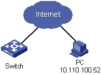
As shown in Figure 1-1, apply an ACL to permit users with the source IP address of 10.110.100.52 to telnet to the switching engine.
Figure 1-1 Network diagram for controlling Telnet login users by source IP
Configuration procedure
# Define ACL 2000.
<device> system-view
[device] acl number 2000
[device-acl-basic-2000] rule 1 permit source 10.110.100.52 0
[device-acl-basic-2000] quit
# Reference ACL 2000 on VTY user interface to control Telnet login users.
[device] user-interface vty 0 4
[device-ui-vty0-4] acl 2000 inbound
Example for Controlling Web Login Users by Source IP
Network requirements
As shown in Figure 1-2, apply an ACL to permit Web users with the source IP address of 10.110.100.46 to log in to the Switch through HTTP.
Figure 1-2 Network diagram for controlling Web login users by source IP

Configuration procedure
# Define ACL 2001.
<device> system-view
[device] acl number 2001
[device-acl-basic-2001] rule 1 permit source 10.110.100.46 0
[device-acl-basic-2001] quit
# Reference ACL 2001 to control users logging in to the Web server.
[device] ip http acl 2001
Examples for Applying ACLs to Hardware
Basic ACL Configuration Example
Network requirements
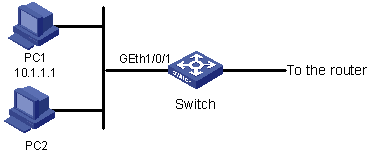
As shown in Figure 1-3, PC1 and PC2 connect to Switch through GigabitEthernet 1/0/1. PC1’s IP address is 10.1.1.1. Apply an ACL on GigabitEthernet 1/0/1 to deny packets with the source IP address of 10.1.1.1 from 8:00 to 18:00 everyday.
Figure 1-3 Network diagram for basic ACL configuration
Configuration procedure
# Define a periodic time range that is active from 8:00 to 18:00 everyday.
<device> system-view
[device] time-range test 8:00 to 18:00 daily
# Define ACL 2000 to filter packets with the source IP address of 10.1.1.1.
[device] acl number 2000
[device-acl-basic-2000] rule 1 deny source 10.1.1.1 0 time-range test
[device-acl-basic-2000] quit
# Apply ACL 2000 on GigabitEthernet 1/0/1.
[device] interface GigabitEthernet1/0/1
[device-GigabitEthernet1/0/1] packet-filter inbound ip-group 2000
Advanced ACL Configuration Example
Network requirements
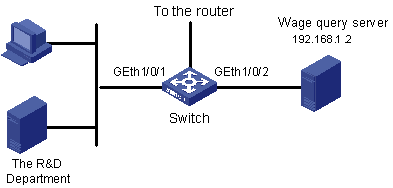
As shown in Figure 1-4, different departments of an enterprise are interconnected through Switch. The IP address of the wage query server is 192.168.1.2. The R&D department is connected to GigabitEthernet 1/0/1 of Switch. Apply an ACL to deny requests from the R&D department and destined for the wage server during the working hours (8:00 to 18:00).
Figure 1-4 Network diagram for advanced ACL configuration
Configuration procedure
# Define a periodic time range that is active from 8:00 to 18:00 everyday.
<device> system-view
[device] time-range test 8:00 to 18:00 working-day
# Define ACL 3000 to filter packets destined for wage query server.
[device] acl number 3000
[device-acl-adv-3000] rule 1 deny ip destination 192.168.1.2 0 time-range test
[device-acl-adv-3000] quit
# Apply ACL 3000 on GigabitEthernet 1/0/1.
[device] interface GigabitEthernet1/0/1
[device-GigabitEthernet1/0/1] packet-filter inbound ip-group 3000
Layer 2 ACL Configuration Example
Network requirements
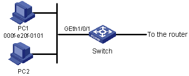
As shown in Figure 1-5, PC1 and PC2 connect to Switch through GigabitEthernet 1/0/1. PC1’s MAC address is 000f-e20f-0101. Apply an ACL to filter packets with the source MAC address of 000f-e20f-0101 and the destination MAC address of 000f-e20f-0303 from 8:00 to 18:00 everyday.
Figure 1-5 Network diagram for Layer 2 ACL
Configuration procedure
# Define a periodic time range that is active from 8:00 to 18:00 everyday.
<device> system-view
[device] time-range test 8:00 to 18:00 daily
# Define ACL 4000 to filter packets with the source MAC address of 000f-e20f-0101 and the destination MAC address of 000f-e20f-0303.
[device] acl number 4000
[device-acl-ethernetframe-4000] rule 1 deny source 000f-e20f-0101 ffff-ffff-ffff dest 000f-e20f-0303 ffff-ffff-ffff time-range test
[device-acl-ethernetframe-4000] quit
# Apply ACL 4000 on GigabitEthernet 1/0/1.
[device] interface GigabitEthernet1/0/1
[device-GigabitEthernet1/0/1] packet-filter inbound link-group 4000
Example for Applying an ACL to a VLAN
Network requirements
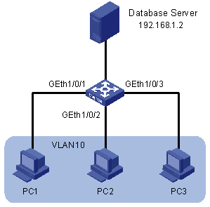
As shown in Figure 1-6, PC1, PC2 and PC3 belong to VLAN 10 and connect to the device through GigabitEthernet 1/0/1, GigabitEthernet 1/0/2 and GigabitEthernet 1/0/3 respectively. The IP address of the database server is 192.168.1.2. Apply an ACL to deny packets from PCs in VLAN 10 to the database server from 8:00 to 18:00 in working days.
Figure 1-6 Network diagram for applying an ACL to a VLAN
Configuration procedure
# Define a periodic time range that is active from 8:00 to 18:00 in working days.
<device> system-view
[device] time-range test 8:00 to 18:00 working-day
# Define an ACL to deny packets destined for the database server.
[device] acl number 3000
[device-acl-adv-3000] rule 1 deny ip destination 192.168.1.2 0 time-range test
[device-acl-adv-3000] quit
# Apply ACL 3000 to VLAN 10.
[device] packet-filter vlan 10 inbound ip-group 3000
