- Table of Contents
-
- H3C WX3000 Series Unified Switches Switching Engine Configuration Guide-6W103
- 00-Preface
- 01-CLI Configuration
- 02-Login Configuration
- 03-Configuration File Management Configuration
- 04-VLAN Configuration
- 05-Auto Detect Configuration
- 06-Voice VLAN Configuration
- 07-GVRP Configuration
- 08-Basic Port Configuration
- 09-Link Aggregation Configuration
- 10-Port Isolation Configuration
- 11-Port Security-Port Binding Configuration
- 12-DLDP Configuration
- 13-MAC Address Table Management Configuration
- 14-MSTP Configuration
- 15-802.1x and System Guard Configuration
- 16-AAA Configuration
- 17-MAC Address Authentication Configuration
- 18-IP Address and Performance Configuration
- 19-DHCP Configuration
- 20-ACL Configuration
- 21-QoS-QoS Profile Configuration
- 22-Mirroring Configuration
- 23-ARP Configuration
- 24-SNMP-RMON Configuration
- 25-Multicast Configuration
- 26-NTP Configuration
- 27-SSH Configuration
- 28-File System Management Configuration
- 29-FTP-SFTP-TFTP Configuration
- 30-Information Center Configuration
- 31-System Maintenance and Debugging Configuration
- 32-VLAN-VPN Configuration
- 33-HWPing Configuration
- 34-DNS Configuration
- 35-Smart Link-Monitor Link Configuration
- 36-PoE-PoE Profile Configuration
- 37-Routing Protocol Configuration
- 38-UDP Helper Configuration
- 39-Acronyms
- 40-Index
- Related Documents
-
| Title | Size | Download |
|---|---|---|
| 15-802.1x and System Guard Configuration | 324.88 KB |
Table of Contents
Architecture of 802.1x Authentication
The Mechanism of an 802.1x Authentication System
Encapsulation of EAPoL Messages
802.1x Authentication Procedure
Additional 802.1x Features Implemented
Introduction to 802.1x Configuration
Configuring Basic 802.1x Functions
Timer and Maximum User Number Configuration
Configuring Client Version Checking
Enabling DHCP-triggered Authentication
Configuring 802.1x Re-Authentication
Configuring the 802.1x Re-Authentication Timer
Displaying and Maintaining 802.1x
2 Quick EAD Deployment Configuration
Introduction to Quick EAD Deployment
Operation of Quick EAD Deployment
Configuring Quick EAD Deployment
Displaying and Maintaining Quick EAD Deployment
Quick EAD Deployment Configuration Example
Configuring the System-Guard Feature
Configuring the System-Guard Feature
Displaying and Maintaining System-Guard
![]()
The sample output information in this manual was created on the WX3024. The output information on your device may vary.
Introduction to 802.1x
The 802.1x protocol (802.1x for short) was developed by IEEE802 LAN/WAN committee to address security issues of wireless LANs. It was then used in Ethernet as a common access control mechanism for LAN ports to address mainly authentication and security problems.
802.1x is a port-based network access control protocol. It authenticates and controls devices requesting for access in terms of the ports of LAN access devices. With the 802.1x protocol employed, a user-side device can access the LAN only when it passes the authentication. Those fail to pass the authentication are denied when accessing the LAN.
Architecture of 802.1x Authentication
As shown in Figure 1-1, 802.1x adopts a client/server architecture with three entities: a supplicant system, an authenticator system, and an authentication server system.
Figure 1-1 Architecture of 802.1x authentication
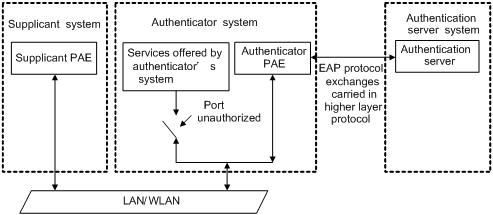
l The supplicant system is the entity seeking access the LAN. It resides at one end of a LAN segment and is authenticated by the authenticator system at the other end of the LAN segment. The supplicant system is usually a user terminal device. 802.1x authentication is triggered when a user launches an 802.1x-capable client program on the supplicant system. Note that the client program must support the extensible authentication protocol over LAN (EAPoL).
l The authenticator system, residing at the other end of the LAN segment link, is the entity that authenticates the connected supplicant system. The authenticator system is usually an 802.1x-supported network device. It provides ports (physical or logical) for the supplicant system to access the LAN.
l The authentication server system is the entity that provides authentication services to the authenticator system. The authentication server system, normally a RADIUS server, serves to perform AAA (authentication, authorization, and accounting) services to users. It also stores user information, such as user name, password, the VLAN a user should belong to, priority, and any ACLs (access control list) to be applied.
There are four additional basic concepts related to 802.1x: port access entity (PAE), controlled port and uncontrolled port, the valid direction of a controlled port and the access control method of a port.
Port access entity
A PAE (port access entity) is responsible for implementing algorithms and performing protocol-related operations in the authentication mechanism.
l The authenticator system PAE authenticates the supplicant systems when they log into the LAN and controls the status (authorized/unauthorized) of the controlled ports according to the authentication result.
l The supplicant system PAE responds to the authentication requests received from the authenticator system and submits user authentication information to the authenticator system. It also sends authentication requests and disconnection requests to the authenticator system PAE.
Controlled port and uncontrolled port
The Authenticator system provides ports for supplicant systems to access a LAN. Logically, a port of this kind is divided into a controlled port and an uncontrolled port.
l The uncontrolled port can always send and receive packets. It mainly serves to forward EAPoL packets to ensure that a supplicant system can send and receive authentication requests.
l The controlled port can be used to pass service packets when it is in authorized state. It is blocked when not in authorized state. In this case, no packets can pass through it.
l Controlled port and uncontrolled port are two properties of a port. Packets reaching a port are visible to both the controlled port and uncontrolled port of the port.
The valid direction of a controlled port
When a controlled port is in unauthorized state, you can configure it to be a unidirectional port, which only sends packets out to supplicant systems.
By default, a controlled port is a unidirectional port.
Port access control method
A port of the device can control user accesses in the following two ways.
l Port-based control. When a port works in the port-based control mode, all the supplicant systems connected to the port can access the network without being authenticated after one supplicant system among them passes the authentication. And when the authenticated supplicant system goes offline, the others are denied as well.
l MAC-based control. When a port works in the MAC-based control mode, all supplicant systems connected to the port have to be authenticated individually in order to access the network. And when a supplicant system goes offline, the others are not affected.
The Mechanism of an 802.1x Authentication System
IEEE 802.1x authentication uses the extensible authentication protocol (EAP) to exchange information between supplicant systems and the authentication servers. To be compatible with 802.1X in a LAN environment, the client program must support the Extensible Authentication Protocol over LAN (EAPoL).
Figure 1-2 The mechanism of an 802.1x authentication system
![]()
l EAP protocol packets transmitted between the supplicant system PAE and the authenticator system PAE are encapsulated as EAPoL packets.
l EAP protocol packets transmitted between the authenticator system PAE and the RADIUS server can either be encapsulated as EAP over RADIUS (EAPoR) packets or be terminated at system PAEs. The system PAEs then communicate with RADIUS servers through password authentication protocol (PAP) or challenge-handshake authentication protocol (CHAP) packets.
l When a supplicant system passes the authentication, the authentication server passes the information about the supplicant system to the authenticator system. The authenticator system in turn determines the state (authorized or unauthorized) of the controlled port according to the instructions (accept or reject) received from the RADIUS server.
Encapsulation of EAPoL Messages
The format of an EAPoL packet
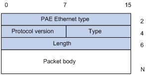
EAPoL is a packet encapsulation format defined in 802.1x. To enable EAP protocol packets to be transmitted between supplicant systems and authenticator systems through LANs, EAP protocol packets are encapsulated in EAPoL format. The following figure illustrates the structure of an EAPoL packet.
Figure 1-3 The format of an EAPoL packet
In an EAPoL packet:
l The PAE Ethernet type field holds the protocol identifier. The identifier for 802.1x is 0x888E.
l The Protocol version field holds the version of the protocol supported by the sender of the EAPoL packet.
l The Type field can be one of the following:
00: Indicates that the packet is an EAP-packet, which carries authentication information.
01: Indicates that the packet is an EAPoL-start packet, which initiates the authentication.
02: Indicates that the packet is an EAPoL-logoff packet, which sends logging off requests.
03: Indicates that the packet is an EAPoL-key packet, which carries key information.
04: Indicates that the packet is an EAPoL-encapsulated-ASF-Alert packet, which is used to support the alerting messages of ASF (alerting standards forum).
l The Length field indicates the size of the Packet body field. A value of 0 indicates that the Packet Body field does not exist.
l The Packet body field differs with the Type field.
Note that EAPoL-Start, EAPoL-Logoff, and EAPoL-Key packets are only transmitted between the supplicant system and the authenticator system. EAP-packets are encapsulated by RADIUS protocol to allow them successfully reach the authentication servers. Network management-related information (such as alarming information) is encapsulated in EAPoL-Encapsulated-ASF-Alert packets, which are terminated by authenticator systems.
The format of an EAP packet
For an EAPoL packet with the value of the Type field being EAP-packet, its Packet body field is an EAP packet, whose format is illustrated in Figure 1-4.
Figure 1-4 The format of an EAP packet
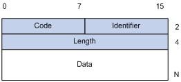
In an EAP packet:
l The Code field indicates the EAP packet type, which can be Request, Response, Success, or Failure.
l The Identifier field is used to match a Response packet with the corresponding Request packet.
l The Length field indicates the size of an EAP packet, which includes the Code, Identifier, Length, and Data fields.
l The Data field carries the EAP packet, whose format differs with the Code field.
A Success or Failure packet does not contain the Data field, so the Length field of it is 4.
Figure 1-5 shows the format of the Data field of a Request packet or a Response packet.
Figure 1-5 The format of the Data field of a Request packet or a Response packet
![]()
l The Type field indicates the EAP authentication type. A value of 1 indicates Identity and that the packet is used to query the identity of the peer. A value of 4 represents MD5-Challenge (similar to PPP CHAP) and indicates that the packet includes query information.
l The Type Date field differs with types of Request and Response packets.
Fields added for EAP authentication
Two fields, EAP-message and Message-authenticator, are added to a RADIUS protocol packet for EAP authentication. (Refer to the Introduction to RADIUS protocol section in AAA in H3C WX3000 Series Unified Switches Switching Engine Configuration Guide for information about the format of a RADIUS protocol packet.)
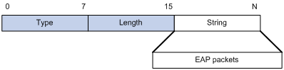
The EAP-message field, whose format is shown in Figure 1-6, is used to encapsulate EAP packets. The maximum size of the string field is 253 bytes. EAP packets with their size larger than 253 bytes are fragmented and are encapsulated in multiple EAP-message fields. The type code of the EAP-message field is 79.
Figure 1-6 The format of an EAP-message field
The Message-authenticator field, whose format is shown in Figure 1-7, is used to prevent unauthorized interception to access requesting packets during authentications using CHAP, EAP, and so on. A packet with the EAP-message field must also have the Message-authenticator field. Otherwise, the packet is regarded as invalid and is discarded.
Figure 1-7 The format of an Message-authenticator field
![]()
802.1x Authentication Procedure
The device can authenticate supplicant systems in EAP terminating mode or EAP relay mode.
EAP relay mode
This mode is defined in 802.1x. In this mode, EAP-packets are encapsulated in higher level protocol (such as EAPoR) packets to enable them to successfully reach the authentication server. Normally, this mode requires that the RADIUS server support the two newly-added fields: the EAP-message field (with a value of 79) and the Message-authenticator field (with a value of 80).
Four authentication ways, namely EAP-MD5, EAP-TLS (transport layer security), EAP-TTLS (tunneled transport layer security), and PEAP (protected extensible authentication protocol), are available in the EAP relay mode.
l EAP-MD5 authenticates the supplicant system. The RADIUS server sends MD5 keys (contained in EAP-request/MD5 challenge packets) to the supplicant system, which in turn encrypts the passwords using the MD5 keys.
l EAP-TLS allows the supplicant system and the RADIUS server to check each other’s security certificate and authenticate each other’s identity, guaranteeing that data is transferred to the right destination and preventing data from being intercepted.
l EAP-TTLS is a kind of extended EAP-TLS. EAP-TLS implements bidirectional authentication between the client and authentication server. EAP-TTLS transmit message using a tunnel established using TLS.
l PEAP creates and uses TLS security channels to ensure data integrity and then performs new EAP negotiations to verify supplicant systems.
Figure 1-8 describes the basic EAP-MD5 authentication procedure.
Figure 1-8 802.1x authentication procedure (in EAP relay mode)
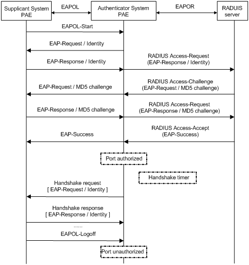
The detailed procedure is as follows:
l A supplicant launches an 802.1x client, and then provides the valid user name and password on the 802.1x client to initiate a connection request. In this case, the 802.1x client program sends the connection request (the EAPoL-start packet) to the device to start the authentication process.
l Upon receiving the authentication request packet, the device sends an EAP-request/identity packet to ask the 802.1x client for the user name.
l The 802.1x client responds by sending an EAP-response/identity packet to the device with the user name contained in it. The device then encapsulates the packet in a RADIUS Access-Request packet and forwards it to the RADIUS server.
l Upon receiving the packet from the device, the RADIUS server retrieves the user name from the packet, finds the corresponding password by matching the user name in its database, encrypts the password using a randomly-generated key, and sends the key to the device through an RADIUS access-challenge packet. The device then sends the key to the 802.1x client.
l Upon receiving the key (encapsulated in an EAP-request/MD5 challenge packet) from the device, the client program encrypts the password of the supplicant system with the key and sends the encrypted password (contained in an EAP-response/MD5 challenge packet) to the RADIUS server through the device. (Normally, the encryption is irreversible.)
l The RADIUS server compares the received encrypted password (contained in a RADIUS access-request packet) with the locally-encrypted password. If the two match, it will then send feedbacks (through a RADIUS access-accept packet and an EAP-success packet) to the device to indicate that the supplicant is authenticated.
l The device changes the state of the corresponding port to accepted state to allow the supplicant to access the network.
l The supplicant can also terminate the authenticated state by sending EAPoL-Logoff packets to the device. The device then changes the port state from accepted to rejected.
![]()
When you configure your device to work in EAP relay mode, you do not need to configure the authentication method to be used. The device and the RADIUS server will negotiate one. The negotiation is initiated by the RADIUS server. Different RADIUS servers support different authentication methods and the order of PEAP, EAP-TLS, EAP-TTLS, and EAP-MD5 in the negotiation may vary.
EAP terminating mode
In this mode, EAP packet transmission is terminated at authenticator systems and the EAP packets are converted to RADIUS packets. Authentication and accounting are carried out through RADIUS protocol.
In this mode, PAP or CHAP is employed between the device and the RADIUS server. Figure 1-9 illustrates the authentication procedure (assuming that CHAP is employed between the device and the RADIUS server).
Figure 1-9 802.1x authentication procedure (in EAP terminating mode)
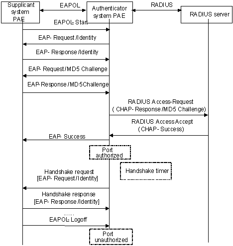
The authentication procedure in EAP terminating mode is the same as that in the EAP relay mode except that the randomly-generated key in the EAP terminating mode is generated by the device, and that it is the device that sends the user name, the randomly-generated key, and the supplicant system-encrypted password to the RADIUS server for further authentication.
Timers Used in 802.1x
In 802.1 x authentication, the following timers are used to ensure that the supplicant system, the device, and the RADIUS server interact in an orderly way.
l Handshake timer (handshake-period). This timer sets the handshake-period and is triggered after a supplicant system passes the authentication. It sets the interval for the device to send handshake request packets to online users. You can set the number of retries by using the dot1x retry command. An online user will be considered offline when the device has not received any response packets after a certain number of handshake request transmission retries.
l Quiet-period timer (quiet-period). This timer sets the quiet-period. When a supplicant system fails to pass the authentication, the device quiets for the set period (set by the quiet-period timer) before it processes another authentication request re-initiated by the supplicant system. During this quiet period, the device does not perform any 802.1x authentication-related actions for the supplicant system.
l Re-authentication timer (reauth-period). The device will initiate 802.1x re-authentication at the interval set by the re-authentication timer.
l RADIUS server timer (server-timeout). This timer sets the server-timeout period. After sending an authentication request packet to the RADIUS server, the device sends another authentication request packet if it does not receive the response from the RADIUS server when this timer times out.
l Supplicant system timer (supp-timeout). This timer sets the supp-timeout period and is triggered by the device after the device sends a request/challenge packet to a supplicant system. The device sends another request/challenge packet to the supplicant system if the device does not receive the response from the supplicant system when this timer times out.
l Transmission timer (tx-period). This timer sets the tx-period and is triggered by the device in two cases. The first case is when the client requests for authentication. The device sends a unicast request/identity packet to a supplicant system and then triggers the transmission timer. The device sends another request/identity packet to the supplicant system if it does not receive the reply packet from the supplicant system when this timer times out. The second case is when the device authenticates the 802.1x client who cannot request for authentication actively. The device sends multicast request/identity packets periodically through the port enabled with 802.1x function. In this case, this timer sets the interval to send the multicast request/identity packets.
l Client version request timer (ver-period). This timer sets the version period and is triggered after the device sends a version request packet. The device sends another version request packet if it does receive version response packets from the supplicant system when the timer expires.
Additional 802.1x Features Implemented
In addition to the earlier mentioned 802.1x features, the device is also capable of the following:
l Checking supplicant systems for proxies, multiple network adapters, etc (This function needs the cooperation of a CAMS server.)
l Checking client version
l The Guest VLAN function
![]()
CAMS Server is a service management system used to manage networks and to secure networks and user information. With the cooperation of other networking devices (such as the WX3000 series devices) in the network, a CAMS server can implement the AAA functions and rights management.
Checking the supplicant system
The device checks:
l Supplicant systems logging on through proxies
l Supplicant systems logging on through IE proxies
l Whether or not a supplicant system logs in through more than one network adapters (that is, whether or not more than one network adapters are active in a supplicant system when the supplicant system logs in).
In response to any of the three cases, the device can optionally take the following measures:
l Only disconnects the supplicant system but sends no Trap packets.
l Sends Trap packets without disconnecting the supplicant system.
This function needs the cooperation of 802.1x client and a CAMS server.
l The 802.1x client needs to capable of detecting multiple network adapters, proxies, and IE proxies.
l The CAMS server is configured to disable the use of multiple network adapters, proxies, or IE proxies.
By default, an 802.1x client program allows use of multiple network adapters, proxies, and IE proxies. In this case, if the CAMS server is configured to disable use of multiple network adapters, proxies, or IE proxies, it prompts the 802.1x client to disable use of multiple network adapters, proxies, or IE proxies through messages after the supplicant system passes the authentication.
![]()
l The client-checking function needs the support of H3C’s 802.1x client program.
l To implement the proxy detecting function, you need to enable the function on both the 802.1x client program and the CAMS server in addition to enabling the client version checking function on the device by using the dot1x version-check command.
Checking the client version
With the 802.1x client version-checking function enabled, the device checks the version and validity of an 802.1x client to prevent unauthorized users or users with earlier versions of 802.1x client from logging in.
This function makes the device to send version-requesting packets again if the 802.1x client fails to send version-reply packet to the device when the version-checking timer times out.
![]()
The 802.1x client version-checking function needs the support of an 802.1x client program.
The Guest VLAN function
The Guest VLAN function enables supplicant systems that are not authenticated to access network resources in a restrained way.
The Guest VLAN function enables supplicant systems that do not have 802.1x client installed to access specific network resources. It also enables supplicant systems that are not authenticated to upgrade their 802.1x client programs.
With this function enabled:
l The device sends authentication request (EAP-Request/Identity) packets to all the 802.1x-enabled ports.
l After the maximum number retries have been made and there are still ports that have not sent any response back, the device will then add these ports to the Guest VLAN.
l Users belonging to the Guest VLAN can access the resources of the Guest VLAN without being authenticated. But they need to be authenticated when accessing external resources.
Normally, the Guest VLAN function is coupled with the dynamic VLAN delivery function.
Refer to AAA in H3C WX3000 Series Unified Switches Switching Engine Configuration Guide for detailed information about the dynamic VLAN delivery function.
Enabling 802.1x re-authentication
802.1x re-authentication is timer-triggered or packet-triggered. It re-authenticates users who have passed authentication. With 802.1x re-authentication enabled, the device can monitor the connection status of users periodically. If the device receives no re-authentication response from a user in a period of time, it tears down the connection to the user. To connect to the device again, the user needs to initiate 802.1x authentication with the client software again.
Figure 1-10 802.1x re-authentication
802.1x re-authentication can be enabled in one of the following two ways:
l The RADIUS server triggers the device to perform 802.1x re-authentication of users. The RADIUS server sends the device an Access-Accept packet with the Termination-Action attribute field of 1. Upon receiving the packet, the device re-authenticates users periodically.
l You enable 802.1x re-authentication on the device. With 802.1x re-authentication enabled, the device re-authenticates users periodically.
![]()
802.1x re-authentication will fail if a CAMS server is used and configured to perform authentication but not accounting. This is because a CAMS server establishes a user session after it begins to perform accounting. Therefore, to enable 802.1x re-authentication, do not configure the accounting none command in the domain. This restriction does not apply to other types of servers.
Introduction to 802.1x Configuration
802.1x provides a solution for authenticating users. To implement this solution, you need to execute 802.1x-related commands. You also need to configure AAA schemes on the device and specify the authentication scheme (RADIUS, HWTACACS or local authentication scheme).
Figure 1-11 802.1x configuration
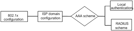
l An 802.1x user uses the domain name to associate with the ISP domain configured on the device.
l Configure the AAA scheme (a local authentication scheme, a RADIUS scheme or a HWTACACS scheme) to be adopted in the ISP domain.
l If you specify to use a local authentication scheme, you need to configure the user names and passwords manually on the device. Users can pass the authentication through 802.1x client if they provide user names and passwords that match those configured on the device.
l If you specify to adopt the RADIUS scheme, users are authenticated by a remote RADIUS server. In this case, you need to configure user names and passwords on the RADIUS server and perform RADIUS client-related configuration on the device.
l If you specify to adopt the HWTACACS scheme, users are authenticated by a remote TACACS server. In this case, you need to configure user names and passwords on the TACACS server and perform HWTACACS client-related configuration on the device.
l You can also specify to adopt the RADIUS or HWTACACS authentication scheme, with a local authentication scheme as a backup. In this case, the local authentication scheme is adopted when the RADIUS server or the TACACS server fails.
Refer to AAA in H3C WX3000 Series Unified Switches Switching Engine Configuration Guide for detailed information about AAA scheme configuration.
Basic 802.1x Configuration
Configuration Prerequisites
l Configure ISP domain and the AAA scheme to be adopted. You can specify a RADIUS scheme, a HWTACACS scheme, or a local scheme.
l Ensure that the service type is configured as lan-access (by using the service-type command) if local authentication scheme is adopted.
Configuring Basic 802.1x Functions
Follow these steps to configure basic 802.1x functions:
|
To do… |
Use the command… |
Remarks |
|
|
Enter system view |
system-view |
— |
|
|
Enable 802.1x globally |
dot1x |
Required By default, 802.1x is disabled globally. |
|
|
Enable 802.1x for specified ports |
In system view |
dot1x [ interface interface-list ] |
Required By default, 802.1x is disabled on all ports. |
|
In port view |
interface interface-type interface-number |
||
|
dot1x |
|||
|
quit |
|||
|
Set port authorization mode for specified ports |
dot1x port-control { authorized-force | unauthorized-force | auto } [ interface interface-list ] |
Optional By default, an 802.1x-enabled port operates in the auto mode. |
|
|
Set the access control method for specified ports |
dot1x port-method { macbased | portbased } [ interface interface-list ] |
Optional The default access control method on a port is MAC-based (that is, the macbased keyword is used by default). |
|
|
Set authentication method for 802.1x users |
dot1x authentication-method { chap | pap | eap } |
Optional By default, the device performs CHAP authentication in EAP terminating mode. |
|
|
Enable online user handshaking |
dot1x handshake enable |
Optional By default, online user handshaking is enabled. |
|
|
Enter Ethernet port view |
interface interface-type interface-number |
— |
|
|
Enable the handshaking packet secure function |
dot1x handshake secure |
Optional By default, the handshaking secure function is disabled. |
|
![]()
l 802.1x configurations take effect only after you enable 802.1x both globally and for specified ports.
l If you enable 802.1x for a port, you cannot set the maximum number of MAC addresses that can be learnt for the port. Meanwhile, if you set the maximum number of MAC addresses that can be learnt for a port, it is prohibited to enable 802.1x for the port.
l If you enable 802.1x for a port, it is not available to add the port to an aggregation group. Meanwhile, if a port has been added to an aggregation group, it is prohibited to enable 802.1x for the port.
l Changing the access control method on a port by the dot1x port-method command will forcibly log out the online 802.1x users on the port.
l When the device itself operates as an authentication server, its authentication method for 802.1x users cannot be configured as EAP.
l Handshaking packets are used to test whether a user is online or not. Users need to run the proprietary client software of H3C to respond to the handshaking packets.
l As clients not running the H3C client software do not support the online user handshaking function, the device cannot receive handshaking acknowledgement packets from the client in handshaking periods. To prevent the user being falsely considered offline, you need to disable the online user handshaking function in this case.
l For the handshaking packet secure function to take effect, the clients that enable the function need to cooperate with the authentication server. If either the clients or the authentication server does not support the function, disabling the handshaking packet secure function is needed.
Timer and Maximum User Number Configuration
Follow these steps to configure 802.1x timers and the maximum number of users:
|
To do… |
Use the command… |
Remarks |
|
|
Enter system view |
system-view |
— |
|
|
Set the maximum number of concurrent on-line users for specified ports |
In system view |
dot1x max-user user-number [ interface interface-list ] |
Optional By default, a port can accommodate up to 256 users at a time. |
|
In port view |
interface interface-type interface-number |
||
|
dot1x max-user user-number |
|||
|
quit |
|||
|
Set the maximum retry times to send request packets |
dot1x retry max-retry-value |
Optional By default, the maximum retry times to send a request packet is 2. That is, the authenticator system sends a request packet to a supplicant system for up to two times by default. |
|
|
Set 802.1x timers |
dot1x timer { handshake-period handshake-period-value | quiet-period quiet-period-value | server-timeout server-timeout-value | supp-timeout supp-timeout-value | tx-period tx-period-value | ver-period ver-period-value } |
Optional The settings of 802.1x timers are as follows. l handshake-period-value: 15 seconds l quiet-period-value: 60 seconds l server-timeout-value: 100 seconds l supp-timeout-value: 30 seconds l tx-period-value: 30 seconds l ver-period-value: 30 seconds |
|
|
Enable the quiet-period timer |
dot1x quiet-period |
Optional By default, the quiet-period timer is disabled. |
|
![]()
l As for the dot1x max-user command, if you execute it in system view without specifying the interface-list argument, the command applies to all ports. You can also use this command in port view. In this case, this command applies to the current port only and the interface-list argument is not needed.
l As for the configuration of 802.1x timers, the default values are recommended.
Advanced 802.1x Configuration
Advanced 802.1x configurations, as listed below, are all optional.
l Configuration concerning CAMS, including multiple network adapters detecting, proxy detecting, and so on.
l Client version checking configuration
l DHCP–triggered authentication
l Guest VLAN configuration
l 802.1x re-authentication configuration
l Configuration of the 802.1x re-authentication timer
You need to configure basic 802.1x functions before configuring the above 802.1x features.
Configuring Proxy Checking
Follow these steps to configure proxy checking:
|
To do… |
Use the command… |
Remarks |
|
|
Enter system view |
system-view |
— |
|
|
Enable proxy checking function globally |
dot1x supp-proxy-check { logoff | trap } |
Required By default, the 802.1x proxy checking function is globally disabled. |
|
|
Enable proxy checking for a port/specified ports |
In system view |
dot1x supp-proxy-check { logoff | trap } [ interface interface-list ] |
Required By default, the 802.1x proxy checking is disabled on a port. |
|
In port view |
interface interface-type interface-number |
||
|
dot1x supp-proxy-check { logoff | trap } |
|||
|
quit |
|||
![]()
l The proxy checking function needs the cooperation of an 802.1x client program.
l The proxy checking function depends on the online user handshaking function. To enable the proxy detecting function, you need to enable the online user handshaking function first.
l The configuration listed in the table above takes effect only when it is performed on CAMS as well as on the device. In addition, the client version checking function needs to be enabled on the device too (by using the dot1x version-check command).
Configuring Client Version Checking
Follow these steps to configure client version checking:
|
To do… |
Use the command… |
Remarks |
|
|
Enter system view |
system-view |
— |
|
|
Enable 802.1x client version checking |
In system view |
dot1x version-check [ interface interface-list ] |
Required By default, 802.1x client version checking is disabled on a port. |
|
In port view |
interface interface-type interface-number |
||
|
dot1x version-check |
|||
|
quit |
|||
|
Set the maximum number of retires to send version checking request packets |
dot1x retry-version-max max-retry-version-value |
Optional By default, the maximum number of retires to send version checking request packets is 3. |
|
|
Set the client version checking period timer |
dot1x timer ver-period ver-period-value |
Optional By default, the timer is set to 30 seconds. |
|
![]()
As for the dot1x version-user command, if you execute it in system view without specifying the interface-list argument, the command applies to all ports. You can also execute this command in port view. In this case, this command applies to the current port only and the interface-list argument is not needed.
Enabling DHCP-triggered Authentication
After performing the following configuration, 802.1x allows running DHCP on access users, and users are authenticated when they apply for dynamic IP addresses through DHCP.
Follow these steps to enable DHCP-triggered authentication:
|
To do… |
Use the command… |
Remarks |
|
Enter system view |
system-view |
— |
|
Enable DHCP-triggered authentication |
dot1x dhcp-launch |
Required By default, DHCP-triggered authentication is disabled. |
Configuring Guest VLAN
Follow these steps to configure Guest VLAN:
|
To do… |
Use the command… |
Remarks |
|
Enter system view |
system-view |
— |
|
Configure the access control method on ports |
dot1x port-method portbased |
Required The default access control method on ports is MAC-based. That is, the macbased keyword is used by default. |
|
Enable the Guest VLAN function |
dot1x guest-vlan vlan-id [ interface interface-list ] |
Required By default, the Guest VLAN function is disabled. |
![]()
l The Guest VLAN function is available only when the device operates in the port-based access control mode.
l Only one Guest VLAN can be configured for each device.
l The Guest VLAN function cannot be implemented if you configure the dot1x dhcp-launch command on the device to enable DHCP-triggered authentication. This is because the device does not send authentication packets unsolicitedly in that case.
Configuring 802.1x Re-Authentication
Follow these steps to enable 802.1x re-authentication:
|
To do… |
Use the command… |
Remarks |
||
|
Enter system view |
system-view |
— |
||
|
Enable 802.1x globally |
dot1x |
Required By default, 802.1x is disabled globally. |
||
|
Enable 802.1x for specified ports |
In system view |
dot1x [ interface interface-list ] |
Required By default, 802.1x is disabled on all ports. |
|
|
In port view |
dot1x |
|||
|
Enable 802.1x re-authentication on port(s) |
In system view |
dot1x re-authenticate [ interface interface-list ] |
Required By default, 802.1x re-authentication is disabled on a port. |
|
|
In port view |
dot1x re-authenticate |
|||
![]()
To enable 802.1x re-authentication on a port, you must first enable 802.1x globally and on the port.
Configuring the 802.1x Re-Authentication Timer
After 802.1x re-authentication is enabled on the device, the device determines the re-authentication interval in one of the following two ways:
1) The device uses the value of the Session-timeout attribute field of the Access-Accept packet sent by the RADIUS server as the re-authentication interval.
2) The device uses the value configured with the dot1x timer reauth-period command as the re-authentication interval for access users.
Note the following:
During re-authentication, the device always uses the latest re-authentication interval configured, no matter which of the above-mentioned two ways is used to determine the re-authentication interval. For example, if you configure a re-authentication interval on the device and the device receives an Access-Accept packet whose Termination-Action attribute field is 1, the device will ultimately use the value of the Session-timeout attribute field as the re-authentication interval.
The following introduces how to configure the 802.1x re-authentication timer on the device.
Follow these steps to configure the re-authentication interval:
|
To do… |
Use the command… |
Remarks |
|
Enter system view |
system-view |
— |
|
Configure a re-authentication interval |
dot1x timer reauth-period reauth-period-value |
Optional By default, the re-authentication interval is 3,600 seconds. |
Displaying and Maintaining 802.1x
|
To do… |
Use the command… |
Remarks |
|
Display the configuration, session, and statistics information about 802.1x |
display dot1x [ sessions | statistics ] [ interface interface-list ] |
Available in any view. |
|
Clear 802.1x-related statistics information |
reset dot1x statistics [ interface interface-list ] |
Available in user view. |
Configuration Example
802.1x Configuration Example
Network requirements
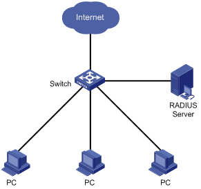
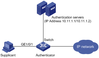
As shown in Figure 1-12:
l Authenticate users on all ports to control their accesses to the Internet. The device (Switch) operates in MAC-based access control mode.
l All supplicant systems that pass the authentication belong to the default domain named “aabbcc.net”. The domain can accommodate up to 30 users. As for authentication, a supplicant system is authenticated locally if the RADIUS server fails. And as for accounting, a supplicant system is disconnected by force if the RADIUS server fails. The name of an authenticated supplicant system is not suffixed with the domain name. A connection is terminated if the total size of the data passes through it during a period of 20 minutes is less than 2,000 bytes.
l The device is connected to a server comprising of two RADIUS servers whose IP addresses are 10.11.1.1 and 10.11.1.2. The RADIUS server with an IP address of 10.11.1.1 operates as the primary authentication server and the secondary accounting server. The other operates as the secondary authentication server and primary accounting server. The password for the device and the authentication RADIUS servers to exchange message is “name”. And the password for the device and the accounting RADIUS servers to exchange message is “money”. The device sends another packet to the RADIUS servers again if it sends a packet to the RADIUS server and does not receive response for 5 seconds, with the maximum number of retries of 5. And the device sends a real-time accounting packet to the RADIUS servers once in every 15 minutes. A user name is sent to the RADIUS servers with the domain name truncated.
l The user name and password for local 802.1x authentication are “localuser” and “localpass” (in plain text) respectively. The idle disconnecting function is enabled.
Figure 1-12 Network diagram for AAA configuration with 802.1x and RADIUS enabled
Configuration procedure
![]()
Following configuration covers the major AAA/RADIUS configuration commands. Refer to AAA in H3C WX3000 Series Unified Switches Switching Engine Command Reference for the information about these commands. Configuration on the client and the RADIUS servers is omitted.
# Enable 802.1x globally.
<device> system-view
System View: return to User View with Ctrl+Z.
[device] dot1x
# Enable 802.1x on GigabitEthernet 1/0/1 port.
[device] dot1x interface GigabitEthernet 1/0/1
# Set the access control method to be MAC-address-based (This operation can be omitted, as MAC-address-based is the default).
[device] dot1x port-method macbased interface GigabitEthernet 1/0/1
# Create a RADIUS scheme named “radius1” and enter RADIUS scheme view.
[device] radius scheme radius1
# Assign IP addresses to the primary authentication and accounting RADIUS servers.
[device-radius-radius1] primary authentication 10.11.1.1
[device-radius-radius1] primary accounting 10.11.1.2
# Assign IP addresses to the secondary authentication and accounting RADIUS server.
[device-radius-radius1] secondary authentication 10.11.1.2
[device-radius-radius1] secondary accounting 10.11.1.1
# Set the password for the switch and the authentication RADIUS servers to exchange messages.
[device-radius-radius1] key authentication name
# Set the password for the switch and the accounting RADIUS servers to exchange messages.
[device-radius-radius1] key accounting money
# Set the interval and the number of the retries for the switch to send packets to the RADIUS servers.
[device-radius-radius1] timer 5
[device-radius-radius1] retry 5
# Set the timer for the switch to send real-time accounting packets to the RADIUS servers.
[device-radius-radius1] timer realtime-accounting 15
# Configure to send the user name to the RADIUS server with the domain name truncated.
[device-radius-radius1] user-name-format without-domain
[device-radius-radius1] quit
# Create the domain named “aabbcc.net” and enter its view.
[device] domain enable aabbcc.net
# Specify to adopt radius1 as the RADIUS scheme of the user domain. If RADIUS server is invalid, specify to adopt the local authentication scheme.
[device-isp-aabbcc.net] scheme radius-scheme radius1 local
# Specify the maximum number of users the user domain can accommodate to 30.
[device-isp-aabbcc.net] access-limit enable 30
# Enable the idle disconnecting function and set the related parameters.
[device-isp-aabbcc.net] idle-cut enable 20 2000
[device-isp-aabbcc.net] quit
# Set the default user domain to be “aabbcc.net”.
[device] domain default enable aabbcc.net
# Create a local access user account.
[device] local-user localuser
[device-luser-localuser] service-type lan-access
[device-luser-localuser] password simple localpass
Introduction to Quick EAD Deployment
Quick EAD Deployment Overview
As an integrated solution, an endpoint admission defense (EAD) solution can improve the overall defense power of a network. In real applications, however, deploying EAD clients proves to be time-consuming and inconvenient.
The device enables the quick deployment of EAD clients by implementing mandatory EAD client distribution through 802.1x authentication.
Operation of Quick EAD Deployment
The device implements quick EAD deployment by leveraging the following two functions to enable mandatory EAD client distribution:
Restricted access
Before passing 802.1x authentication, a user is restricted (through ACLs) to a specific range of IP addresses or a specific server. Services like EAD client upgrading/download and dynamic address assignment are available on the specific server.
HTTP redirection
Whenever a user accesses the Internet through the Internet Explorer (IE) before passing 802.1x authentication, the device redirects the user to a predefined URL, such as the EAD client download interface.
With the above two functions of quick EAD deployment, the device redirects all users to a server to download and install the EAD client, resolving the EAD client deployment problem.
![]()
The quick EAD deployment feature takes effect only when the authorization mode of an 802.1x-enabled port is set to auto.
Configuring Quick EAD Deployment
Configuration Prerequisites
l Enable 802.1x on the device.
l Set the port authorization mode to auto for 802.1x-enabled ports.
Configuration Procedure
Configuring a free IP range
A free IP range is an IP range that users can access before passing 802.1x authentication.
Follow these steps to configure a free IP range:
|
To do… |
Use the command… |
Remarks |
|
Enter system view |
system-view |
— |
|
Configure the URL for HTTP redirection |
dot1x url url-string |
Required |
|
Configure a free IP range |
dot1x free-ip ip-address { mask-address | mask-length } |
Required By default, no free IP range is configured. |
![]()
l You must configure the URL for HTTP redirection before configuring a free IP range. A URL must start with http:// and the segment where the URL resides must be in the free IP range. Otherwise, the redirection function cannot take effect.
l You must disable the DHCP-triggered authentication function of 802.1x before configuring a free IP range.
l With dot1x enabled but quick EAD deployment disabled, users cannot access the DHCP server if they fail 802.1x authentication. With quick EAD deployment enabled, users can obtain IP addresses dynamically before passing authentication if the IP address of the DHCP server is in the free IP range.
l The quick EAD deployment function applies to only ports with the authorization mode set to auto through the dot1x port-control command.
l Currently, the quick EAD deployment function is implemented based on only 802.1x authentication.
l Currently, the quick EAD deployment function does not support port security. The configured free IP range cannot take effect if you enable port security.
Setting the ACL timeout period
The quick EAD deployment function depends on ACLs in restricting access of users failing authentication. Each online user that has not passed authentication occupies a certain amount of ACL resources. After a user passes authentication, the occupied ACL resources will be released. When a large number of users log in but cannot pass authentication, the device may run out of ACL resources, preventing other users from logging in. A timer called ACL timer is designed to solve this problem.
You can control the usage of ACL resources by setting the ACL timer. The ACL timer starts once a user gets online. If the user has not passed authentication when the ACL timer expires, the occupied ACL resources are released for other users to use. If the device has a larger number of users, you can decrease the timeout period of the ACL timer appropriately for higher utilization of ACL resources.
Follow these steps to configure the ACL timer:
|
To do… |
Use the command… |
Remarks |
|
Enter system view |
system-view |
— |
|
Set the ACL timer |
dot1x timer acl-timeout acl-timeout-value |
Required By default, the ACL timeout period is 30 minutes. |
Displaying and Maintaining Quick EAD Deployment
|
To do… |
Use the command… |
Remarks |
|
Display configuration information about quick EAD deployment |
display dot1x [ sessions | statistics ] [ interface interface-list ] |
Available in any view. |
Quick EAD Deployment Configuration Example
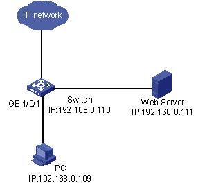
Network requirements
As shown in Figure 2-1, a user (PC) connects to the device (Switch) directly. The device connects to the Web server and the Internet. The user will be redirected to the Web server to download the authentication client and upgrade software when accessing the Internet through IE before passing authentication. After passing authentication, the user can access the Internet.
Figure 2-1 Network diagram for quick EAD deployment
Configuration procedure
![]()
Before enabling quick EAD deployment, make sure that:
l The Web server is configured properly.
l The default gateway of the PC is configured as the IP address of the Layer-3 virtual interface of the VLAN to which the port that is directly connected with the PC belongs.
# Configure the URL for HTTP redirection.
<device> system-view
[device] dot1x url http://192.168.0.111
# Configure a free IP range.
[device] dot1x free-ip 192.168.0.111 24
# Set the ACL timer to 10 minutes.
[device] dot1x timer acl-timeout 10
# Enable dot1x globally.
[device] dot1x
# Enable dot1x for GigabitEthernet 1/0/1.
[device] dot1x interface GigabitEthernet 1/0/1
Troubleshooting
Symptom: A user cannot be redirected to the specified URL server, no matter what URL the user enters in the IE address bar.
Solution:
l If a user enters an IP address in a format other than the dotted decimal notation, the user may not be redirected. This is related with the operating system used on the PC. In this case, the PC considers the IP address string a name and tries to resolve the name. If the resolution fails, the PC will access a specific website. Generally, this address is not in dotted decimal notation. As a result, the PC cannot receive any ARP response and therefore cannot be redirected. To solve this problem, the user needs to enter an IP address that is not in the free IP range in dotted decimal notation.
l If a user enters an address in the free IP range, the user cannot be redirected. This is because the device considers that the user wants to access a host in the free IP range. This is true even if no host with the IP address exists. To solve this problem, the user needs to enter an address not in the free IP range.
l Check that you have configured an IP address in the free IP range for the Web server and a correct URL for redirection, and that the server provides Web services properly.
System-Guard Overview
At first, you must determine whether the CPU is under attack to implement system guard for the CPU.
You should not determine whether the CPU is under attack just according to whether congestion occurs in a queue. Instead, you must do that in the following ways:
l According to the number of packets processed in the CPU in a time range.
l Or according to the time for one hundred packets to be processed.
If the CPU is under attack, the rate of packets to be processed in the CPU in a certain queue will exceed the threshold value. In this case, you can determine that the CPU is under attack. Through analyzing these packets, you get to know the characteristics of the attack source, and then you can adopt different filtering rules according the characteristics of the attack source. Thus, system guard is implemented.
Configuring the System-Guard Feature
Configuring the System-Guard Feature
Follow these steps to configure the system-guard feature:
|
To do… |
Use the command… |
|
|
Enter system view |
system-view |
— |
|
Enable the system-guard feature |
system-guard enable |
Required By default, the system-guard feature is disabled. |
|
Set the threshold for the number of packets when an attack is detected |
system-guard detect-threshold threshold-value |
Optional The default threshold value is 200 packets. |
|
Set the length of the isolation after an attack is detected |
system-guard timer-interval isolate-timer |
Optional By default, the length of the isolation after an attack is detected is 10 minutes. |
Displaying and Maintaining System-Guard
|
To do… |
Use the command… |
Remarks |
|
Display the record of detected attacks |
display system-guard attack-record |
Available in any view |
|
Display the state of the system-guard feature |
display system-guard state |
Available in any view |
