- Table of Contents
-
- H3C WX3000 Series Unified Switches Switching Engine Configuration Guide-6W103
- 00-Preface
- 01-CLI Configuration
- 02-Login Configuration
- 03-Configuration File Management Configuration
- 04-VLAN Configuration
- 05-Auto Detect Configuration
- 06-Voice VLAN Configuration
- 07-GVRP Configuration
- 08-Basic Port Configuration
- 09-Link Aggregation Configuration
- 10-Port Isolation Configuration
- 11-Port Security-Port Binding Configuration
- 12-DLDP Configuration
- 13-MAC Address Table Management Configuration
- 14-MSTP Configuration
- 15-802.1x and System Guard Configuration
- 16-AAA Configuration
- 17-MAC Address Authentication Configuration
- 18-IP Address and Performance Configuration
- 19-DHCP Configuration
- 20-ACL Configuration
- 21-QoS-QoS Profile Configuration
- 22-Mirroring Configuration
- 23-ARP Configuration
- 24-SNMP-RMON Configuration
- 25-Multicast Configuration
- 26-NTP Configuration
- 27-SSH Configuration
- 28-File System Management Configuration
- 29-FTP-SFTP-TFTP Configuration
- 30-Information Center Configuration
- 31-System Maintenance and Debugging Configuration
- 32-VLAN-VPN Configuration
- 33-HWPing Configuration
- 34-DNS Configuration
- 35-Smart Link-Monitor Link Configuration
- 36-PoE-PoE Profile Configuration
- 37-Routing Protocol Configuration
- 38-UDP Helper Configuration
- 39-Acronyms
- 40-Index
- Related Documents
-
| Title | Size | Download |
|---|---|---|
| 19-DHCP Configuration | 302.04 KB |
Obtaining IP Addresses Dynamically
2 DHCP Relay Agent Configuration
Introduction to DHCP Relay Agent
DHCP Relay Agent Support for Option 82
Configuring the DHCP Relay Agent
DHCP Relay Agent Configuration Task List
Correlating a DHCP Server Group with a Relay Agent Interface
Configuring DHCP Relay Agent Security Functions
Configuring the DHCP Relay Agent to Support Option 82
Displaying and Maintaining DHCP Relay Agent Configuration
DHCP Relay Agent Configuration Example
Troubleshooting DHCP Relay Agent Configuration
Overview of DHCP Snooping Option 82
Configuring DHCP Snooping to Support Option 82
DHCP Snooping Configuration Example
DHCP-Snooping Option 82 Support Configuration Example
IP Filtering Configuration Example
Displaying and Maintaining DHCP Snooping Configuration
4 DHCP/BOOTP Client Configuration
Configuring a DHCP/BOOTP Client
l The term switch used throughout this document refers to a switching device in a generic sense or the switching engine of the WX3000 series.
l The sample output information in this manual was created on the WX3024. The output information on your device may vary.
1 DHCP Overview
Introduction to DHCP
With networks getting larger in size and more complicated in structure, lack of available IP addresses becomes the common situation the network administrators have to face, and network configuration becomes a tough task for the network administrators. With the emerging of wireless networks and the using of laptops, the position change of hosts and frequent change of IP addresses also require new technology. Dynamic host configuration protocol (DHCP) is developed to solve these issues.
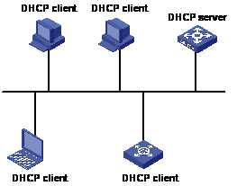
DHCP adopts a client/server model, where the DHCP clients send requests to DHCP servers for configuration parameters; and the DHCP servers return the corresponding configuration information such as IP addresses to implement dynamic allocation of network resources.
A typical DHCP application includes one DHCP server and multiple clients (such as PCs and laptops), as shown in Figure 1-1.
Figure 1-1 Typical DHCP application
DHCP IP Address Assignment
IP Address Assignment Policy
Currently, DHCP provides the following three IP address assignment policies to meet the requirements of different clients:
l Manual assignment. The administrator configures static IP-to-MAC bindings for some special clients, such as a WWW server. Then the DHCP server assigns these fixed IP addresses to the clients.
l Automatic assignment. The DHCP server assigns IP addresses to DHCP clients. The IP addresses will be occupied by the DHCP clients permanently.
l Dynamic assignment. The DHCP server assigns IP addresses to DHCP clients for predetermined period of time. In this case, a DHCP client must apply for an IP address again at the expiration of the period. This policy applies to most clients.
Obtaining IP Addresses Dynamically
A DHCP client undergoes the following four phases to dynamically obtain an IP address from a DHCP server:
1) Discover: In this phase, the DHCP client tries to find a DHCP server by broadcasting a DHCP-DISCOVER packet.
2) Offer: In this phase, the DHCP server offers an IP address. After the DHCP server receives the DHCP-DISCOVER packet from the DHCP client, it chooses an unassigned IP address from the address pool according to the priority order of IP address assignment and then sends the IP address and other configuration information together in a DHCP-OFFER packet to the DHCP client. The sending mode is decided by the flag filed in the DHCP-DISCOVER packet, refer to DHCP Packet Format for details.
3) Select: In this phase, the DHCP client selects an IP address. If more than one DHCP server sends DHCP-OFFER packets to the DHCP client, the DHCP client only accepts the DHCP-OFFER packet that first arrives, and then broadcasts a DHCP-REQUEST packet containing the assigned IP address carried in the DHCP-OFFER packet.
![]()
l After the client receives the DHCP-ACK message, it will probe whether the IP address assigned by the server is in use by broadcasting a gratuitous ARP packet. If the client receives no response within specified time, the client can use this IP address. Otherwise, the client sends a DHCP-DECLINE message to the server and requests an IP address again.
l If there are multiple DHCP servers, IP addresses offered by other DHCP servers are assignable to other clients.
Updating IP Address Lease
After a DHCP server dynamically assigns an IP address to a DHCP client, the IP address keeps valid only within a specified lease time and will be reclaimed by the DHCP server when the lease expires. If the DHCP client wants to use the IP address for a longer time, it must update the IP lease.
By default, a DHCP client updates its IP address lease automatically by unicasting a DHCP-REQUEST packet to the DHCP server when half of the lease time elapses. The DHCP server responds with a DHCP-ACK packet to notify the DHCP client of a new IP lease if the server can assign the same IP address to the client. Otherwise, the DHCP server responds with a DHCP-NAK packet to notify the DHCP client that the IP address will be reclaimed when the lease time expires.
If the DHCP client fails to update its IP address lease when half of the lease time elapses, it will update its IP address lease by broadcasting a DHCP-REQUEST packet to the DHCP servers again when seven-eighths of the lease time elapses. The DHCP server performs the same operations as those described above.
DHCP Packet Format
DHCP has eight types of packets. They have the same format, but the values of some fields in the packets are different. The DHCP packet format is based on that of the BOOTP packets. The following figure describes the packet format (the number in the brackets indicates the field length, in bytes):
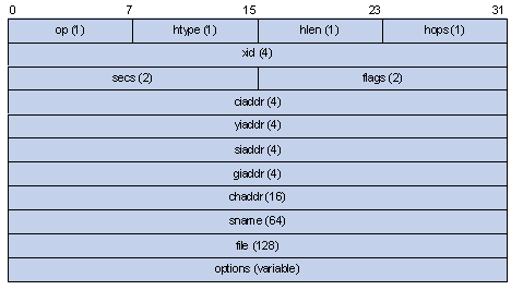
The fields are described as follows:
l op: Operation types of DHCP packets, 1 for request packets and 2 for response packets.
l htype, hlen: Hardware address type and length of the DHCP client.
l hops: Number of DHCP relay agents which a DHCP packet passes. For each DHCP relay agent that the DHCP request packet passes, the field value increases by 1.
l xid: Random number that the client selects when it initiates a request. The number is used to identify an address-requesting process.
l secs: Elapsed time after the DHCP client initiates a DHCP request.
l flags: The first bit is the broadcast response flag bit, used to identify that the DHCP response packet is a unicast (set to 0) or broadcast (set to 1). Other bits are reserved.
l ciaddr: IP address of a DHCP client.
l yiaddr: IP address that the DHCP server assigns to a client.
l siaddr: IP address of the DHCP server.
l giaddr: IP address of the first DHCP relay agent that the DHCP client passes after it sent the request packet.
l chaddr: Hardware address of the DHCP client.
l sname: Name of the DHCP server.
l file: Path and name of the boot configuration file that the DHCP server specifies for the DHCP client.
l option: Optional variable-length fields, including packet type, valid lease time, IP address of a DNS server, and IP address of the WINS server.
Protocols and Standards
l RFC 2131: Dynamic Host Configuration Protocol
l RFC 2132: DHCP Options and BOOTP Vendor Extensions
l RFC 1542: Clarifications and Extensions for the Bootstrap Protocol
l RFC 3046: DHCP Relay Agent Information option
When configuring the DHCP relay agent, go to these sections for information you are interested in:
l Introduction to DHCP Relay Agent
l Configuring the DHCP Relay Agent
l Displaying and Maintaining DHCP Relay Agent Configuration
l DHCP Relay Agent Configuration Example
l Troubleshooting DHCP Relay Agent Configuration
Currently, the interface-related DHCP relay agent configurations can only be made on VLAN interfaces.
Introduction to DHCP Relay Agent
Usage of DHCP Relay Agent
Since the packets are broadcasted in the process of obtaining IP addresses, DHCP is only applicable to the situation that DHCP clients and DHCP servers are in the same network segment, that is, you need to deploy at least one DHCP server for each network segment, which is far from economical.
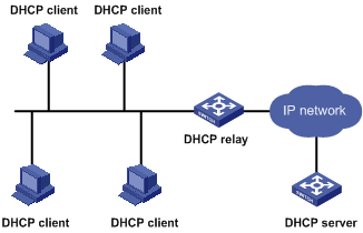
DHCP relay agent is designed to address this problem. It enables DHCP clients in a subnet to communicate with the DHCP server in another subnet so that the DHCP clients can obtain IP addresses. In this case, the DHCP clients in multiple networks can use the same DHCP server, which can decrease your cost and provide a centralized administration.
DHCP Relay Agent Fundamentals
Figure 2-1 illustrates a typical DHCP relay agent application.
Figure 2-1 Typical DHCP relay agent application
In the process of dynamic IP address assignment through the DHCP relay agent, the DHCP client and DHCP server interoperate with each other in a similar way as they do without the DHCP relay agent. The following sections only describe the forwarding process of the DHCP relay agent. For the interaction process of the packets, see Obtaining IP Addresses Dynamically.
1) After receiving the DHCP-DISCOVER or DHCP-REQUEST broadcast from the client, the network device providing the DHCP relay agent function unicasts the message to the designated DHCP server based on the configuration.
2) The DHCP server selects an IP address and other parameters and sends the configuration information to the DHCP relay agent that relays the information to the client (the sending mode is decided by the flag filed in the client’s DHCP-DISCOVER packet, refer to DHCP Packet Format for details).
DHCP Relay Agent Support for Option 82
Introduction to Option 82
Option 82 is the relay agent information option in the DHCP message. It records the location information of the DHCP client. With this option, the administrator can locate the DHCP client to further implement security control and accounting. The Option 82 supporting server can also use such information to define individual assignment policies of IP address and other parameters for the clients.
Option 82 involves at most 255 sub-options. If Option 82 is defined, at least one sub-option must be defined. Currently the DHCP relay agent supports two sub-options: sub-option 1 (circuit ID sub-option) and sub-option 2 (remote ID sub-option).
Padding content of Option 82
Option 82 has no unified definition in RFC 3046. Its padding information varies with vendors. Currently, the device that operates as a DHCP relay agent supports the extended padding format of Option 82 sub-options. By default, the sub-options of Option 82 are padded as follows, as shown in Figure 2-2 and Figure 2-3. (The content in brackets is the fixed value of each field.)
l Sub-option 1: Padded with the port index (smaller than the physical port number by 1) and VLAN ID of the port that received the client’s request.
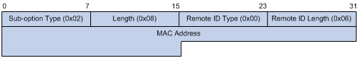
l Sub-option 2: Padded with the bridge MAC address of the DHCP relay agent device that received the client’s request.
Figure 2-2 Padding contents for sub-option 1 of Option 82
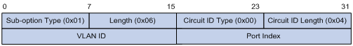
Figure 2-3 Padding contents for sub-option 2 of Option 82
Mechanism of Option 82 supported on DHCP relay agent
The procedure for a DHCP client to obtain an IP address from a DHCP server through a DHCP relay agent is similar to that for the client to obtain an IP address from a DHCP server directly. The following are the mechanism of Option 82 support on DHCP relay agent.
1) Upon receiving a DHCP request, the DHCP relay agent checks whether the packet contains Option 82 and processes the packet accordingly.
l If the request packet contains Option 82, the DHCP relay agent processes the packet depending on the configured strategy (that is, discards the packet, replaces the original Option 82 in the packet with its own, or leaves the original Option 82 unchanged in the packet), and forwards the packet (if not discarded) to the DHCP server.
l If the request packet does not contain Option 82, the DHCP relay agent adds Option 82 to the packet and forwards the packet to the DHCP server.
2) Upon receiving the packet returned from the DHCP server, the DHCP relay agent strips Option 82 from the packet and forwards the packet with the DHCP configuration information to the DHCP client.
![]()
Request packets sent by a DHCP client fall into two categories: DHCP-DISCOVER packets and DHCP-REQUEST packets. As DHCP servers coming from different manufacturers process DHCP request packets in different ways (that is, some DHCP servers process Option 82 in DHCP-DISCOVER packets, whereas the rest process Option 82 in DHCP-REQUEST packets), a DHCP relay agent adds Option 82 to both types of packets to accommodate to DHCP servers of different manufacturers.
Configuring the DHCP Relay Agent
![]()
If a device belongs to an IRF fabric, you need to enable the UDP Helper function on it before configuring it as a DHCP relay agent.
DHCP Relay Agent Configuration Task List
Complete the following tasks to configure the DHCP relay agent:
|
Task |
Remarks |
|
Correlating a DHCP Server Group with a Relay Agent Interface |
Required |
|
Optional |
|
|
Optional |
Correlating a DHCP Server Group with a Relay Agent Interface
To enhance reliability, you can set multiple DHCP servers on the same network. These DHCP servers form a DHCP server group. When an interface of the relay agent establishes a correlation with the DHCP server group, the interface will forward received DHCP packets to all servers in the server group.
Follow these steps to correlate a DHCP server group with a relay agent interface:
|
To do… |
Use the command… |
Remarks |
|
Enter system view |
system-view |
— |
|
Configure the DHCP server IP address(es) in a specified DHCP server group |
dhcp-server groupNo ip ip-address&<1-8> |
Required By default, no DHCP server IP address is configured in a DHCP server group. |
|
Map an interface to a DHCP server group |
interface interface-type interface-number |
Required By default, a VLAN interface is not mapped to any DHCP server group. |
|
dhcp-server groupNo |
![]()
To improve security and avoid malicious attack to the unused SOCKETs, the device provides the following functions:
l UDP 67 and UDP 68 ports used by DHCP are enabled only when DHCP is enabled.
l UDP 67 and UDP 68 ports are disabled when DHCP is disabled.
The corresponding implementation is as follows:
l When a VLAN interface is mapped to a DHCP server group with the dhcp-server command, the DHCP relay agent is enabled. At the same time, UDP 67 and UDP 68 ports used by DHCP are enabled.
l When the mapping between a VLAN interface and a DHCP server group is removed with the undo dhcp-server command, DHCP services are disabled. At the same time, UDP 67 and UDP 68 ports are disabled.
![]()
l You can configure up to eight DHCP server IP addresses in a DHCP server group.
l You can map multiple VLAN interfaces to one DHCP server group. But one VLAN interface can be mapped to only one DHCP server group.
l If you execute the dhcp-server groupNo command repeatedly, the new configuration overwrites the previous one.
l You need to configure the group number specified in the dhcp-server groupNo command in VLAN interface view by using dhcp-server groupNo ip ip-address&<1-8> in advance.
Configuring DHCP Relay Agent Security Functions
Configuring address checking
After relaying an IP address from the DHCP server to a DHCP client, the DHCP relay agent can automatically record the client’s IP-to-MAC binding and generate a dynamic address entry. It also supports static bindings, which means you can manually configure IP-to-MAC bindings on the DHCP relay agent, so that users can access external network using fixed IP addresses.
The purpose of the address checking function on DHCP relay agent is to prevent unauthorized users from statically configuring IP addresses to access external networks. With this function enabled, a DHCP relay agent inhibits a user from accessing external networks if the IP address configured on the user end and the MAC address of the user end do not match any entries (including the entries dynamically tracked by the DHCP relay agent and the manually configured static entries) in the user address table on the DHCP relay agent.
Follow these steps to configure address checking:
|
To do… |
Use the command… |
Remarks |
|
Enter system view |
system-view |
— |
|
Create a static IP-to-MAC binding |
dhcp-security static ip-address mac-address |
Optional Not created by default. |
|
Enter interface view |
interface interface-type interface-number |
— |
|
Enable the address checking function |
address-check enable |
Required Disabled by default. |
![]()
l The address-check enable command is independent of other commands of the DHCP relay agent. That is, the invalid address check takes effect when this command is executed, regardless of whether other commands (such as the command to enable DHCP) are used.
l Before executing the address-check enable command on the interface connected to the DHCP server, you need to configure the static binding of the IP address to the MAC address of the DHCP server. Otherwise, the DHCP client will fail to obtain an IP address.
Configuring the dynamic client address entry updating function
After relaying an IP address from the DHCP server to the DHCP client, the DHCP relay agent can automatically record the client’s IP-to-MAC binding and generate a dynamic address entry. But as a DHCP relay agent does not process DHCP-RELEASE packets, which are sent to DHCP servers by DHCP clients through unicast when the DHCP clients release IP addresses, the user address entries maintained by the DHCP cannot be updated in time. You can solve this problem by enabling the DHCP relay agent handshake function and configuring the dynamic client address entry updating interval.
After the handshake function is enabled, the DHCP relay agent sends the handshake packet (the DHCP-REQUEST packet) periodically to the DHCP server using a client’s IP address and its own MAC address.
l If the DHCP relay agent receives the DHCP-ACK packet from the DHCP server, or receives no response from the server within a specified period, the IP address can be assigned. The DHCP relay agent ages out the corresponding entry in the client address table.
l If the DHCP relay agent receives the DHCP-NAK packet from the DHCP server, the lease of the IP address does not expire. The DHCP relay agent does not age out the corresponding entry.
Follow these steps to configure the dynamic user address entry updating function:
|
To do… |
Use the command… |
Remarks |
|
Enter system view |
system-view |
— |
|
Enable the DHCP relay agent handshake function |
dhcp relay hand enable |
Optional Enabled by default. |
|
Set the interval at which the DHCP relay agent dynamically updates the client address entries |
dhcp-security tracker { interval | auto } |
Optional By default, auto is adopted, that is, the interval is automatically calculated. |
Enabling unauthorized DHCP server detection
If there is an unauthorized DHCP server in the network, when a client applies for an IP address, the unauthorized DHCP server may assign an incorrect IP address to the DHCP client.
With this feature enabled, upon receiving a DHCP message with the siaddr field (IP addresses of the servers offering IP addresses to the client) not being 0 from a client, the DHCP relay agent will record the value of the siaddr field and the receiving interface. The administrator can use this information to check out any DHCP unauthorized servers.
Follow these steps to enable unauthorized DHCP server detection:
|
To do… |
Use the command… |
Remarks |
|
Enter system view |
system-view |
— |
|
Enable unauthorized DHCP server detection |
dhcp-server detect |
Required Disabled by default. |
![]()
With the unauthorized DHCP server detection enabled, the relay agent will log all DHCP servers, including authorized ones, and each server is recorded only once until such information is removed and is recorded again. The administrator needs to find unauthorized DHCP servers from the system log information.
Configuring the DHCP Relay Agent to Support Option 82
Prerequisites
Before configuring Option 82 support on a DHCP relay agent, you need to:
l Configure network parameters and relay function of the DHCP relay device.
l Perform assignment strategy-related configurations, such as network parameters of the DHCP server, address pool, and lease time.
l The routes between the DHCP relay agent and the DHCP server are reachable.
Configuring the DHCP relay agent to support Option 82
Follow these steps to configure the DHCP relay agent to support Option 82:
|
To do… |
Use the command… |
Remarks |
|
Enter system view |
system-view |
— |
|
Enable Option 82 support on the DHCP relay agent |
dhcp relay information enable |
Required Disabled by default. |
|
Configure the strategy for the DHCP relay agent to process request packets containing Option 82 |
dhcp relay information strategy { drop | keep | replace } |
Optional By default, the replace strategy is adopted |
l By default, with the Option 82 support function enabled on the DHCP relay agent, the DHCP relay agent will adopt the replace strategy to process the request packets containing Option 82. However, if other strategies are configured before, then enabling the 82 support on the DHCP relay agent will not change the configured strategies.
l To enable Option 82, you need to perform the corresponding configuration on the DHCP server and the DHCP relay agent.
Displaying and Maintaining DHCP Relay Agent Configuration
|
To do… |
Use the command… |
Remarks |
|
Display the information about a specified DHCP server group |
display dhcp-server groupNo |
Available in any view |
|
Display the information about the DHCP server group to which a specified VLAN interface is mapped |
display dhcp-server interface vlan-interface vlan-id |
|
|
Display the specified client address entries on the DHCP relay agent |
display dhcp-security [ ip-address | dynamic | static | tracker ] |
|
|
Clear the statistics information of the specified DHCP server group |
reset dhcp-server groupNo |
Available in user view |
DHCP Relay Agent Configuration Example
Network requirements
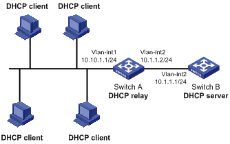
As shown in Figure 2-4, VLAN-interface 1 on the DHCP relay agent (Switch A) connects to the network where DHCP clients reside. The IP address of VLAN-interface 1 is 10.10.1.1/24 and IP address of VLAN-interface 2 is 10.1.1.2/24 that communicates with the DHCP server 10.1.1.1/24. As shown in the figure below, Switch A forwards messages between DHCP clients and the DHCP server to assign IP addresses in subnet 10.10.1.0/24 to the clients.
Figure 2-4 Network diagram for DHCP relay agent
Configuration procedure
# Create DHCP server group 1 and configure an IP address of 10.1.1.1 for it.
<SwitchA> system-view
[SwitchA] dhcp-server 1 ip 10.1.1.1
# Map VLAN-interface 1 to DHCP server group 1.
[SwitchA] interface vlan-interface 1
[SwitchA-Vlan-interface1] dhcp-server 1
![]()
l You need to perform corresponding configurations on the DHCP server to enable the DHCP clients to obtain IP addresses from the DHCP server. The DHCP server configurations vary with different DHCP server devices, so the configurations are omitted.
l The DHCP relay agent and DHCP server must be reachable to each other.
Troubleshooting DHCP Relay Agent Configuration
Symptom
A client fails to obtain configuration information through a DHCP relay agent.
Analysis
This problem may be caused by improper DHCP relay agent configuration. When a DHCP relay agent operates improperly, you can locate the problem by enabling debugging and checking the information about debugging and interface state (You can display the information by executing the corresponding display command.)
Solution
l Check if DHCP is enabled on the DHCP server and the DHCP relay agent.
l Check if an address pool that is on the same network segment with the DHCP clients is configured on the DHCP server.
l Check if a reachable route is configured between the DHCP relay agent and the DHCP server.
l Check the DHCP relay agent. Check if the correct DHCP server group is configured on the interface connecting the network segment where the DHCP client resides. Check if the IP address of the DHCP server group is correct.
l If the address-check enable command is configured on the interface connected to the DHCP server, verify the DHCP server’s IP-to-MAC address binding entry is configured on the DHCP relay agent; otherwise the DHCP client cannot obtain an IP address.
![]()
After DHCP snooping is enabled on a device, clients connected with the device cannot obtain IP addresses dynamically through BOOTP.
DHCP Snooping Overview
Function of DHCP Snooping
For security, the IP addresses used by online DHCP clients need to be tracked for the administrator to verify the corresponding relationship between the IP addresses the DHCP clients obtained from DHCP servers and the MAC addresses of the DHCP clients.
l Switches can track DHCP clients’ IP addresses through the security function of the DHCP relay agent operating at the network layer.
l Switches can track DHCP clients’ IP addresses through the DHCP snooping function at the data link layer.
When an unauthorized DHCP server exists in the network, a DHCP client may obtains an illegal IP address. To ensure that the DHCP clients obtain IP addresses from valid DHCP servers, you can specify a port to be a trusted port or an untrusted port by the DHCP snooping function.
l Trusted: A trusted port is connected to an authorized DHCP server directly or indirectly. It forwards DHCP messages to guarantee that DHCP clients can obtain valid IP addresses.
l Untrusted: An untrusted port is connected to an unauthorized DHCP server. The DHCP-ACK or DHCP-OFFER packets received from the port are discarded, preventing DHCP clients from receiving invalid IP addresses.
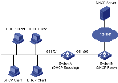
Figure 3-1 illustrates a typical network diagram for DHCP snooping application, where Switch A is a WX3000 series device.
Figure 3-1 Typical network diagram for DHCP snooping application
DHCP snooping listens the following two types of packets to retrieve the IP addresses the DHCP clients obtain from DHCP servers and the MAC addresses of the DHCP clients:
l DHCP-REQUEST packet
l DHCP-ACK packet
Overview of DHCP Snooping Option 82
Introduction to Option 82
Option 82 is the relay agent information option in the DHCP message. It records the location information of the DHCP client.
When a DHCP relay agent (or a device enabled with DHCP snooping) receives a client’s request, it adds the Option 82 to the request message and sends it to the server.
The administrator can locate the DHCP client to further implement security control and accounting. The Option 82 supporting server can also use such information to define individual assignment policies of IP address and other parameters for the clients.
Option 82 involves at most 255 sub-options. If Option 82 is defined, at least one sub-option must be defined. Currently the DHCP relay agent supports two sub-options: sub-option 1 (circuit ID sub-option) and sub-option 2 (remote ID sub-option).
Padding content and frame format of Option 82
There is no specification for what should be padded in Option 82. Manufacturers can pad it as required. By default, the sub-options of Option 82 for the device (enabled with DHCP snooping) are padded as follows:
l Sub-option 1 (circuit ID sub-option): Padded with the port index (smaller than the physical port number by 1) and VLAN ID of the port that received the client’s request.
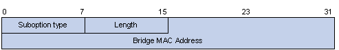
l Sub-option 2 (remote ID sub-option): Padded with the bridge MAC address of the DHCP snooping device that received the client’s request.
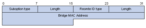
By default, when the device serves as a DHCP snooping device, Option 82 adopts the extended format. Refer to Table 3-2 and Figure 3-3 for the extended format of the sub-options (with the default padding contents). That is, the circuit ID or remote ID sub-option defines the type and length of a circuit ID or remote ID.
The remote ID type field and circuit ID type field are determined by the option storage format. They are both set to “0” in the case of HEX format and to “1” in the case of ASCII format.
Figure 3-2 Extended format of the circuit ID sub-option
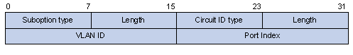
Figure 3-3 Extended format of the remote ID sub-option
In practice, some network devices do not support the type and length identifiers of the Circuit ID and Remote ID sub-options. To interwork with these devices, the device supports Option 82 in the standard format. Refer to Figure 3-4 and Figure 3-5 for the standard format of the sub-options (with the default padding contents). In the standard format, the Circuit ID or Remote ID sub-option does not contain the two-byte type and length fields of the circuit ID or remote ID.
Figure 3-4 Standard format of the circuit ID sub-option
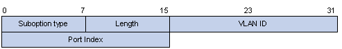
Figure 3-5 Standard format of the remote ID sub-option
Mechanism of DHCP-snooping Option 82
With DHCP snooping and DHCP-snooping Option 82 support enabled, when the DHCP snooping device receives a DHCP client’s request containing Option 82, it will handle the packet according to the handling policy and the configured contents in sub-options. For details, see Table 3-1.
Table 3-1 Ways of handling a DHCP packet with Option 82
|
Handling policy |
Sub-option configuration |
The DHCP snooping device will… |
|
Drop |
— |
Drop the packet. |
|
Keep |
— |
Forward the packet without changing Option 82. |
|
Replace |
Neither of the two sub-options is configured |
Forward the packet after replacing the original Option 82 with the default content. The storage format of Option 82 content is the one specified with the dhcp-snooping information format command or the default HEX format if this command is not executed. |
|
Circuit ID sub-option is configured |
Forward the packet after replacing the circuit ID sub-option of the original Option 82 with the configured circuit ID sub-option in ASCII format. |
|
|
Remote ID sub-option is configured |
Forward the packet after replacing the remote ID sub-option of the original Option 82 with the configured remote ID sub-option in ASCII format. |
When receiving a DHCP client’s request without Option 82, the DHCP snooping device will add the option field with the configured sub-option and then forward the packet. For details, see Table 3-2.
Table 3-2 Ways of handling a DHCP packet without Option 82
|
Sub-option configuration |
The DHCP snooping device will… |
|
Neither of the two sub-options is configured. |
Forward the packet after adding Option 82 with the default contents. The format of Option 82 is the one specified with the dhcp-snooping information format command or the default HEX format if this command is not executed. |
|
Circuit ID sub-option is configured. |
Forward the packet after adding Option 82 with the configured circuit ID sub-option in ASCII format. |
|
Remote ID sub-option is configured. |
Forward the packet after adding Option 82 with the configured remote ID sub-option in ASCII format. |
![]()
The circuit ID and remote ID sub-options in Option 82, which can be configured simultaneously or separately, are independent of each other in terms of configuration sequence.
When the DHCP snooping device receives a DHCP response packet from the DHCP server, the DHCP snooping device will delete the Option 82 field, if contained, before forwarding the packet, or will directly forward the packet if the packet does not contain the Option 82 field.
Overview of IP Filtering
A denial-of-service (DoS) attack means an attempt of an attacker sending a large number of forged address requests with different source IP addresses to the server so that the network cannot work normally. The specific effects are as follows:
l The resources on the server are exhausted, so the server does not respond to other requests.
l After receiving such type of packets, a device needs to send them to the CPU for processing. Too many request packets cause high CPU usage rate. As a result, the CPU cannot work normally.
The device can filter invalid IP packets through the DHCP-snooping table and IP static binding table.
DHCP-snooping table
After DHCP snooping is enabled on a device, a DHCP-snooping table is generated. It is used to record IP addresses obtained from the DHCP server, MAC addresses, the number of the port through which a client is connected to the DHCP-snooping-enabled device, and the number of the VLAN to which the port belongs to. These records are saved as entries in the DHCP-snooping table.
IP static binding table
The DHCP-snooping table only records information about clients that obtains IP address dynamically through DHCP. If a fixed IP address is configured for a client, the IP address and MAC address of the client cannot be recorded in the DHCP-snooping table. Consequently, this client cannot pass the IP filtering of the DHCP-snooping table, thus it cannot access external networks.
To solve this problem, the device supports the configuration of static binding table entries, that is, the binding relationship between IP address, MAC address, and the port connecting to the client, so that packets of the client can be correctly forwarded.
IP filtering
The device can filter IP packets in the following two modes:
l Filtering the source IP address in a packet. If the source IP address and the number of the port that receives the packet are consistent with entries in the DHCP-snooping table or static binding table, the device regards the packet as a valid packet and forwards it; otherwise, the device drops it directly.
l Filtering the source IP address and the source MAC address in a packet. If the source IP address and source MAC address in the packet, and the number of the port that receives the packet are consistent with entries in the DHCP-snooping table or static binding table, the device regards the packet as a valid packet and forwards it; otherwise, the device drops it directly.
DHCP Snooping Configuration
Configuring DHCP Snooping
Follow these steps to configure DHCP snooping:
|
To do… |
Use the command… |
Remarks |
|
Enter system view |
system-view |
— |
|
Enable DHCP snooping |
dhcp-snooping |
Required By default, the DHCP snooping function is disabled. |
|
Enter Ethernet port view |
interface interface-type interface-number |
— |
|
Specify the current port as a trusted port |
dhcp-snooping trust |
Required By default, after DHCP snooping is enabled, all ports of a device are untrusted ports. |
![]()
l You need to specify the ports connected to the valid DHCP servers as trusted to ensure that DHCP clients can obtain valid IP addresses. The trusted port and the port connected to the DHCP client must be in the same VLAN.
l You are not recommended to configure both the DHCP snooping and selective QinQ function on the device, which may result in the DHCP snooping to function abnormally.
Configuring DHCP Snooping to Support Option 82
![]()
Enable DHCP snooping and specify trusted ports on the device before configuring DHCP snooping to support Option 82.
DHCP-Snooping Option 82 Support Configuration Task List
Complete the following tasks to configure DHCP-snooping Option 82 support:
|
Task |
Remarks |
|
Required |
|
|
Optional |
|
|
Optional |
|
|
Optional |
|
|
Optional |
|
|
Optional |
Enable DHCP-snooping Option 82 support
Follow these steps to enable DHCP-snooping Option 82 support:
|
To do… |
Use the command… |
Remarks |
|
Enter system view |
system-view |
— |
|
Enable DHCP-snooping Option 82 support |
dhcp-snooping information enable |
Required By default, DHCP snooping Option 82 support is disabled. |
Configure a handling policy for DHCP packets with Option 82
Follow these steps to configure a handling policy for DHCP packets with Option 82:
|
To do… |
Use the command… |
Remarks |
|
Enter system view |
system-view |
Optional |
|
Configure a global handling policy for requests that contain Option 82 |
dhcp-snooping information strategy { drop | keep | replace } |
Optional The default handling policy is replace. |
|
Enter Ethernet port view |
interface interface-type interface-number |
— |
|
Configure a handling policy for requests that contain Option 82 received on the specified interface |
dhcp-snooping information strategy { drop | keep | replace } |
Optional The default policy is replace. |
![]()
If a handling policy is configured on a port, this configuration overrides the globally configured handling policy for requests received on this port, while the globally configured handling policy applies on those ports where a handling policy is not natively configured.
Configure the storage format of Option 82
The device supports the HEX or ASCII format for the Option 82 field.
Follow these steps to configure a storage format for the Option 82 field:
|
To do… |
Use the command… |
Remarks |
|
Enter system view |
system-view |
— |
|
Configure a storage format for the Option 82 field |
dhcp-snooping information format { hex | ascii } |
Optional By default, the format is hex. |
![]()
The dhcp-snooping information format command applies only to the default content of the Option 82 field. If you have configured the circuit ID or remote ID sub-option, the format of the sub-option is ASCII, instead of the one specified with the dhcp-snooping information format command.
Configure the circuit ID sub-option
Follow these steps to configure the circuit ID sub-option:
|
To do… |
Use the command… |
Remarks |
|
Enter system view |
system-view |
— |
|
Enter Ethernet port view |
interface interface-type interface-number |
— |
|
Configure the circuit ID sub-option in Option 82 |
dhcp-snooping information [ vlan vlan-id ] circuit-id string string |
Optional By default, the circuit ID sub-option contains the VLAN ID and port index related to the port that receives DHCP request packets from DHCP clients |
![]()
l In a port aggregation group, you can use this command to configure the primary and member ports respectively. When Option 82 is added, however, the circuit ID sub-option is subject to the one configured on the primary port.
l The circuit ID sub-option configured on a port will not be synchronized in the case of port aggregation.
Configure the remote ID sub-option
You can configure the remote ID sub-option in system view or Ethernet port view:
l In system view, the remote ID takes effect on all interfaces. You can configure Option 82 as the system name (sysname) of the device or any customized character string in the ASCII format.
l In Ethernet port view, the remote ID takes effect only on the current interface. You can configure Option 82 as any customized character string in the ASCII format for different VLANs. That is to say, you can add different configuration rules for packets from different VLANs.
Follow these steps to configure the remote ID sub-option in Option 82:
|
To do… |
Use the command… |
Remarks |
|
Enter system view |
system-view |
— |
|
Configure the remote ID sub-option in system view |
dhcp-snooping information remote-id { sysname | string string } |
Optional By default, the remote ID sub-option is the MAC address of the DHCP snooping device that received the DHCP client’s request. |
|
Enter Ethernet port view |
interface interface-type interface-number |
— |
|
Configure the remote ID sub-option in Ethernet port view |
dhcp-snooping information [ vlan vlan-id ] remote-id string string |
Optional By default, the remote ID sub-option is the MAC address of the DHCP snooping device that received the client’s request. |
![]()
l If you configure a remote ID sub-option in both system view and on a port, the remote ID sub-option configured on the port applies when the port receives a packet, and the global remote ID applies to other interfaces that have no remote ID sub-option configured.
l In a port aggregation group, you can use this command to configure the primary and member ports respectively. When Option 82 is added, however, the remote ID is subject to the one configured on the primary port.
l The remote ID configured on a port will not be synchronized in the case of port aggregation.
Configure the padding format for Option 82
Follow these steps to configure the padding format for Option 82:
|
To do… |
Use the command… |
Remarks |
|
Enter system view |
system-view |
— |
|
Configure the padding format |
dhcp-snooping information packet-format { extended | standard } |
Optional By default, the padding format is in extended format. |
Configuring IP Filtering
Follow these steps to configure IP filtering:
|
To do… |
Use the command… |
Remarks |
|
Enter system view |
system-view |
— |
|
Enter Ethernet port view |
interface interface-type interface-number |
— |
|
Enable IP filtering |
ip check source ip-address [ mac-address ] |
Required By default, this function is disabled. |
|
Create an IP static binding entry |
ip source static binding ip-address ip-address [ mac-address mac-address ] |
Optional By default, no static binding entry is created. |
![]()
l Enable DHCP snooping and specify trusted ports on the device before configuring IP filtering.
l You are not recommended to configure IP filtering on the ports of an aggregation group.
DHCP Snooping Configuration Example
DHCP-Snooping Option 82 Support Configuration Example
Network requirements
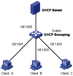
As shown in Figure 3-6, GigabitEthernet 1/0/5 of Switch is connected to the DHCP server, and GigabitEthernet 1/0/1, GigabitEthernet 1/0/2, and GigabitEthernet 1/0/3 are respectively connected to Client A, Client B, and Client C.
l Enable DHCP snooping on Switch.
l Specify GigabitEthernet 1/0/5 on Switch as a trusted port for DHCP snooping.
l Enable DHCP-snooping Option 82 support on Switch and set the remote ID field in Option 82 to the system name of Switch. Set the circuit ID sub-option to “abcd” in DHCP packets from VLAN 1 on GigabitEthernet 1/0/3.
Figure 3-6 Network diagram for DHCP-snooping Option 82 support configuration
Configuration procedure
# Enable DHCP snooping on Switch.
<Switch> system-view
[Switch] dhcp-snooping
# Specify GigabitEthernet 1/0/5 as the trusted port.
[Switch] interface gigabitethernet 1/0/5
[Switch-GigabitEthernet1/0/5] dhcp-snooping trust
[Switch-GigabitEthernet1/0/5] quit
# Enable DHCP-snooping Option 82 support.
[Switch] dhcp-snooping information enable
# Set the remote ID sub-option in Option 82 to the system name (sysname) of the DHCP snooping device.
[Switch] dhcp-snooping information remote-id sysname
# Set the circuit ID sub-option in DHCP packets from VLAN 1 to “abcd” on GigabitEthernet 1/0/3.
[Switch] interface gigabitethernet 1/0/3
[Switch-GigabitEthernet1/0/3] dhcp-snooping information vlan 1 circuit-id string abcd
IP Filtering Configuration Example
Network requirements
As shown in Figure 3-7, GigabitEthernet 1/0/1 of Switch is connected to DHCP server and GigabitEthernet 1/0/2 is connected to Host A. The IP address and MAC address of Host A are 1.1.1.1 and 0001-0001-0001 respectively. GigabitEthernet 1/0/3 and GigabitEthernet 1/0/4 is connected to DHCP Client B and Client C.
l Enable DHCP snooping on Switch, and specify GigabitEthernet 1/0/1 as the DHCP snooping trusted port to prevent attacks from unauthorized DHCP servers.
l Enable IP filtering on GigabitEthernet 1/0/2, GigabitEthernet 1/0/3, and GigabitEthernet 1/0/4 to prevent attacks to the server from clients using fake source IP addresses.
l Create static binding entries on Switch, so that Host A using a fixed IP address can access the external network.
Figure 3-7 Network diagram for IP filtering configuration

Configuration procedure
# Enable DHCP snooping on Switch.
<Switch> system-view
[Switch] dhcp-snooping
# Specify GigabitEthernet 1/0/1 as the trusted port.
[Switch] interface gigabitethernet 1/0/1
[Switch-GigabitEthernet1/0/1] dhcp-snooping trust
[Switch-GigabitEthernet1/0/1] quit
# Enable IP filtering on GigabitEthernet 1/0/2, GigabitEthernet 1/0/3, and GigabitEthernet 1/0/4 to filter packets based on the source IP addresses/MAC addresses.
[Switch] interface gigabitethernet 1/0/2
[Switch-GigabitEthernet1/0/2] ip check source ip-address mac-address
[Switch-GigabitEthernet1/0/2] quit
[Switch] interface gigabitethernet 1/0/3
[Switch-GigabitEthernet1/0/3] ip check source ip-address mac-address
[Switch-GigabitEthernet1/0/3] quit
[Switch] interface gigabitethernet 1/0/4
[Switch-GigabitEthernet1/0/4] ip check source ip-address mac-address
[Switch-GigabitEthernet1/0/4] quit
# Create static binding entries on GigabitEthernet 1/0/2 of Switch.
[Switch] interface gigabitethernet 1/0/2
[Switch-GigabitEthernet1/0/2] ip source static binding ip-address 1.1.1.1 mac-address 0001-0001-0001
Displaying and Maintaining DHCP Snooping Configuration
|
To do… |
Use the command… |
Remarks |
|
Display the user IP-MAC address mapping entries recorded by the DHCP snooping function |
display dhcp-snooping [ unit unit-id ] |
Available in any view |
|
Display the (enabled/disabled) state of the DHCP snooping function and the trusted ports |
display dhcp-snooping trust |
|
|
Display the IP static binding table |
display ip source static binding [ vlan vlan-id | interface interface-type interface-number ] |
Introduction to DHCP Client
After you specify a VLAN interface as a DHCP client, the device can use DHCP to obtain parameters such as IP address dynamically from the DHCP server, which facilitates user configuration and management.
Refer to Obtaining IP Addresses Dynamically for the process of how a DHCP client dynamically obtains an IP address through DHCP.
Introduction to BOOTP Client
After you specify an interface as a bootstrap protocol (BOOTP) client, the interface can use BOOTP to get information (such as IP address) from the BOOTP server, which simplifies your configuration.
Before using BOOTP, an administrator needs to configure a BOOTP parameter file for each BOOTP client on the BOOTP server. The parameter file contains information such as MAC address and IP address of a BOOTP client. When a BOOTP client sends a request to the BOOTP server, the BOOTP server will search for the BOOTP parameter file and return it to the client.
A BOOTP client dynamically obtains an IP address from a BOOTP server in the following way:
1) The BOOTP client broadcasts a BOOTP request, which contains its own MAC address.
2) The BOOTP server receives the request and searches for the corresponding IP address according to the MAC address of the BOOTP client and sends the information in a BOOTP response to the BOOTP client.
3) The BOOTP client obtains the IP address from the received response.
![]()
Because a DHCP server can interact with a BOOTP client, you can use the DHCP server to assign an IP address to the BOOTP client, without needing to configure any BOOTP server.
Configuring a DHCP/BOOTP Client
Follow these steps to configure a DHCP/BOOTP client:
|
To do… |
Use the command… |
Remarks |
|
Enter system view |
system-view |
— |
|
Enter VLAN interface view |
interface vlan-interface vlan-id |
— |
|
Configure the VLAN interface to obtain IP address through DHCP or BOOTP |
ip address { bootp-alloc | dhcp-alloc } |
Required By default, no IP address is configured for the VLAN interface. |
![]()
Currently, the device operating as a DHCP client can use an IP address for no more than 24 days; that is, it can obtain a lease with 24 days at most even if the DHCP server assigns a lease with more than 24 days.
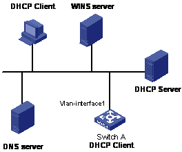
DHCP Client Configuration Example
Network requirements
As shown in Figure 4-1, using DHCP, VLAN-interface 1 of Switch A is connected to the LAN to obtain an IP address from the DHCP server.
Figure 4-1 A DHCP network (Switch A serving as a DHCP client)
Configuration procedure
The following describes only the configuration on Switch A serving as a DHCP client.
# Configure VLAN-interface 1 to dynamically obtain an IP address by using DHCP.
<SwitchA> system-view
[SwitchA] interface vlan-interface 1
[SwitchA-Vlan-interface1] ip address dhcp-alloc
Displaying and Maintaining DHCP/BOOTP Client Configuration
|
To do… |
Use the command… |
Remarks |
|
Display related information on a DHCP client |
display dhcp client [ verbose ] |
Available in any view |
|
Display related information on a BOOTP client |
display bootp client [ interface vlan-interface vlan-id ] |
