- Table of Contents
-
- H3C UniServer B16000 Blade Server Configuration Examples-6W100
- 01-FC and FCoE Services Configuration Examples
- 02-Ethernet Services Configuration Examples
- 03-Virtual Management Network Configuration Examples
- 04-Shared Storage Configuration Examples
- 05-VC Configuration Examples
- 06-Chassis Profile Configuration Examples
- 07-IB Service Configuration Examples
- 08-Blade Server FIST Configuration Examples
- Related Documents
-
| Title | Size | Download |
|---|---|---|
| 08-Blade Server FIST Configuration Examples | 500.43 KB |
Example: Configuring single-chassis management through OM module links
Creating AE primary/backup cluster
Example: Configuring multi-chassis management through OM module links
Configuring dual-channel cascading
Creating AE primary/backup cluster
Example: Configuring multi-chassis management through ICM module links
Creating AE primary/backup cluster
Checking hardware configuration with FIST
Connecting ICM modules to TOR switches
Configuring the interconnect module
Comparison of networking verification results
Introduction
To manage blade servers of B16000 blade chassis in batches through the FIST management software, such as configuring HDM in batches in several blade servers, configuring RAID, and managing OS, you need to set up FIST networking in AE modules in the B16000 blade chassis. FIST management networking of the B16000 blade chassis is divided into two types according to link connection modes of FIST service network, including the management through OM module links and the management through ICM module links.
Networking modes
As the FIST management software is installed in the AE modules, service traffic is transmitted through links connected to the AE modules.
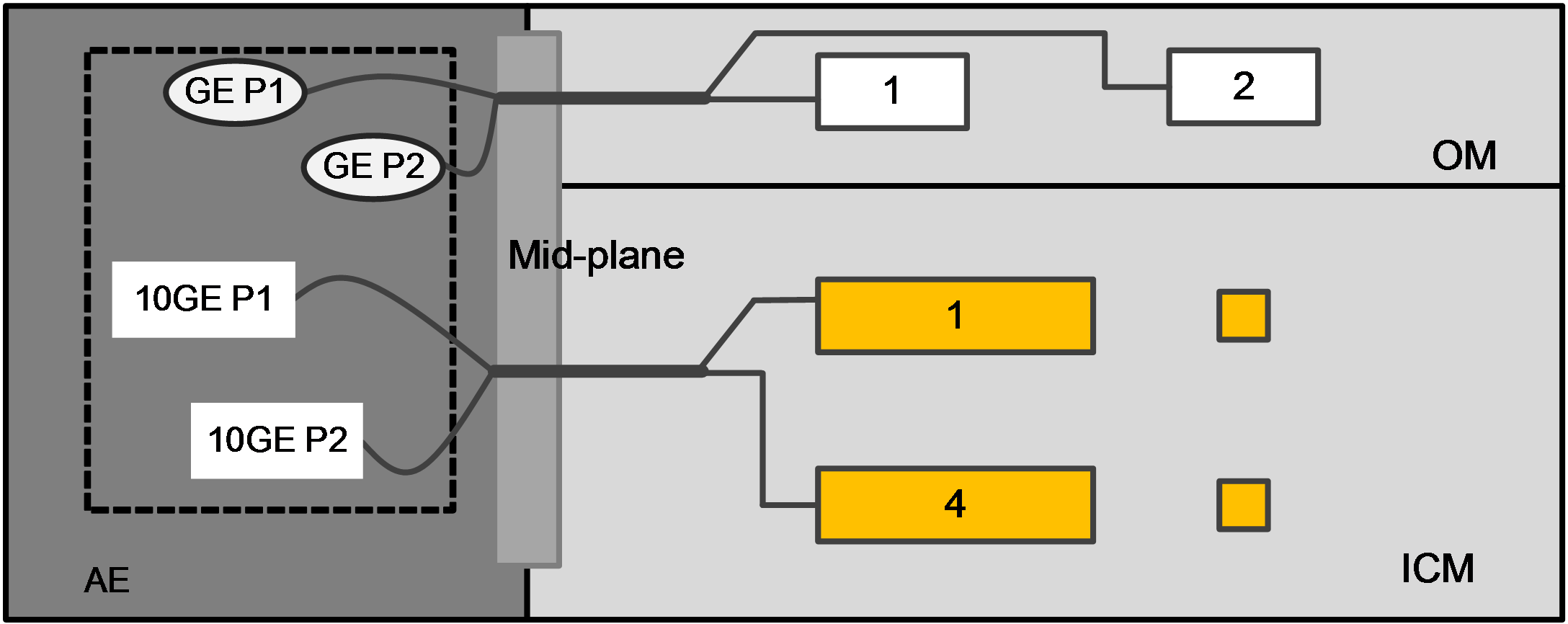
As shown in Figure 1, four onboard Ethernet ports of the AE modules inside the B16000 blade chassis are connected to OM modules and ICM modules through a midplane, two GE interfaces are connected to the primary and backup OM modules, and two 10 GE interfaces are connected to ICM modules in slots 1 and 4. Users may access the FIST management software in the AE modules by connecting to a management port of an OM module or a front-panel Ethernet port of an ICM module.
Figure 1 Connection of AE module in chassis
Based on link connection methods of the FIST service network, there are two networking modes:
· As shown in Figure 2, the FIST service links are connected through the OM module.
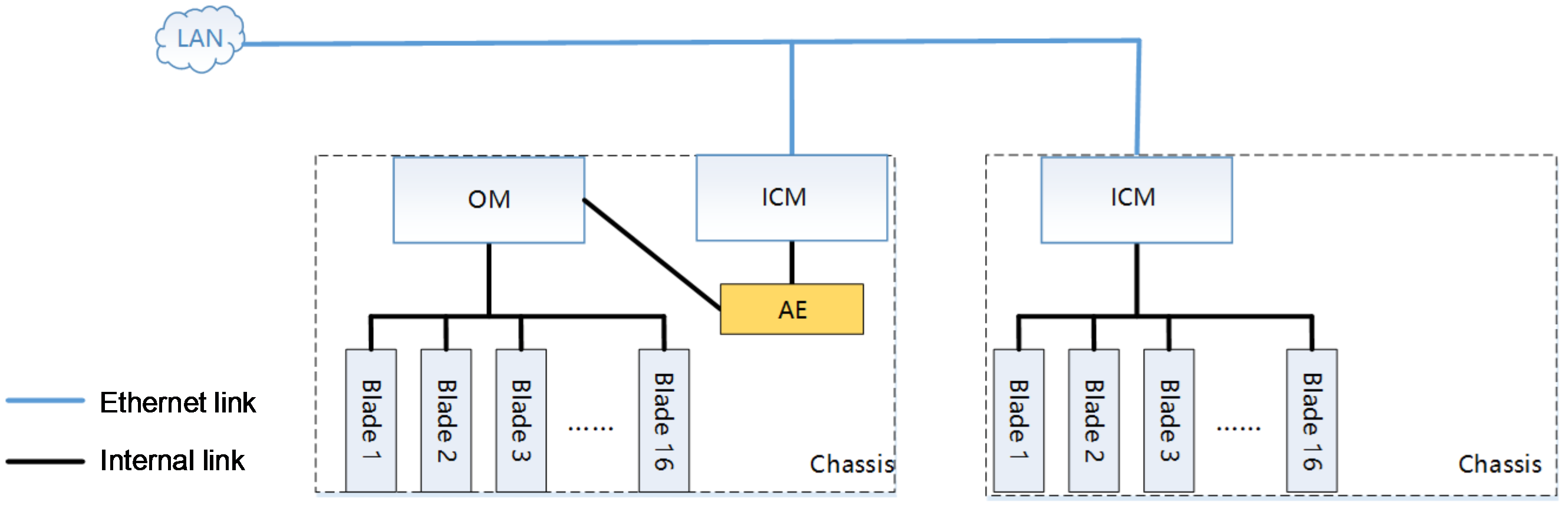
· As shown in Figure 3, the FIST service links are connected through the ICM module.
Figure 2 Connecting FIST service links through OM module
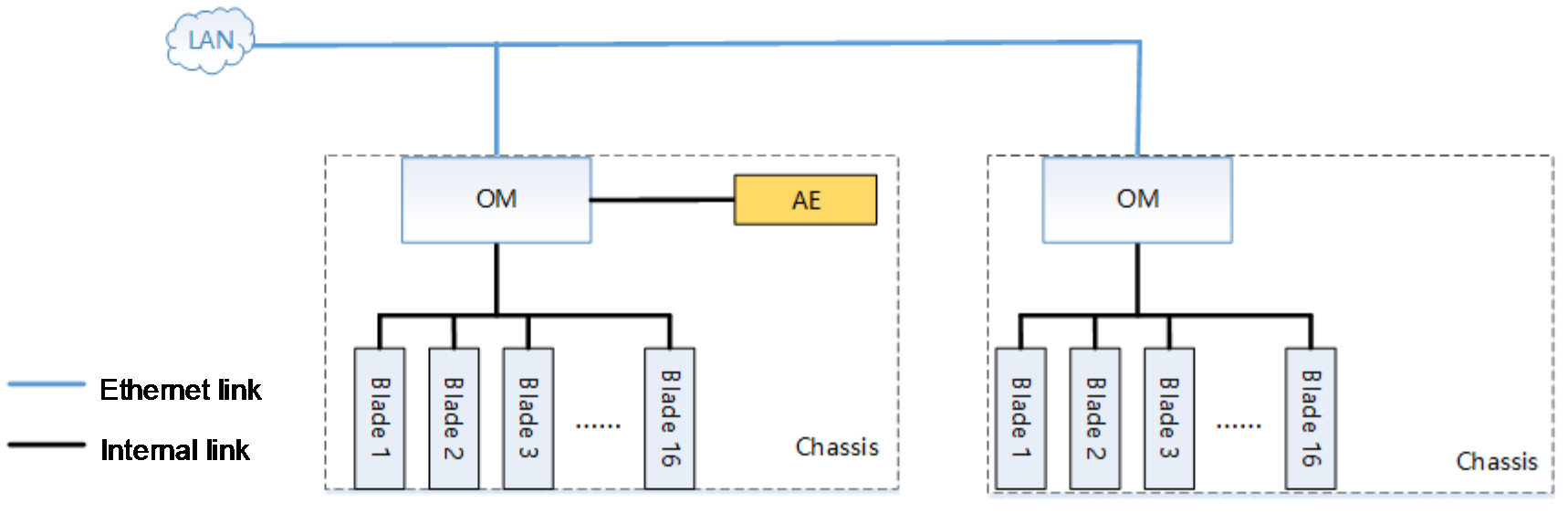
Figure 3 Connecting FIST service links through ICM module
Comparison between two networking modes is shown in Table 1.
Table 1 Comparison between two networking modes
|
Networking mode |
Characteristics |
Bandwidth |
Applicable scenarios |
|
Connecting FIST links through OM module |
· Transmit FIST service traffic through OM module. · The networking & building is relatively simple, sharing links with the OM management network. |
A single port supports a maximum 10 Gbps bandwidth. |
· Applies to single-chassis or multi-chassis management service scenario. · Applies to service networks of relatively low network loads. |
|
Connecting FIST links through ICM module |
· Transmit FIST service traffic through ICM module. · The network & building is relatively complicated, sharing links with the service network and requiring configuration of multiple devices and parameters. · Only this networking mode supports the cross-chassis and no-disk boot. |
A single port supports more than 10 Gbps bandwidth. |
· Applies to multi-chassis management service scenarios. · Applies to complicated service networks. · Applies to service networks of high loads and traffic. · Applies to service scenarios requiring high bandwidth. |
Hardware compatibility
As shown in Table 2, this section describes hardware to be used in each typical networking mode.
Table 2 Hardware compatibility for typical networking mode
|
Configuration example |
Hardware compatibility and model |
|||
|
AE module |
Mezz network adapter |
Interconnection module |
External switch |
|
|
Managing through OM module links |
· AE100 · AE101 |
NA |
NA |
NA |
|
Managing through ICM module links |
· AE100 · AE101 |
· NIC-ETH521i-Mb-4*10G · NIC-ETH522i-Mb-2*10G |
· BX720E · BX720EF |
· Ethernet switch of any model |
|
NOTE: · When multiple hardware models are listed in one cell, it indicates that these hardware models all apply to the configuration example. · "-" indicates that it is unnecessary to configure this hardware. |
||||
Prerequisites
The configuration examples were created and verified in a lab environment, and all the devices were started with the factory default configuration. The following information is provided based on the assumption that you have basic knowledge of AE primary/backup relationship, Ethernet, switch IRF, port aggregation, H3C blade server, ICM module, and FIST management software.
The following information mainly describes link connection methods of FIST service network in the AE modules of the B16000 blade chassis. As a best practice, configure ICM module settings as needed, such as VLAN configuration.
Example: Configuring single-chassis management through OM module links
Network requirement
As shown in Figure 4, the following components are installed in one H3C Uniserver B16000 blade chassis:
· One AE module, with the pre-installed FIST management software, is respectively installed in the slots E1 and E2 in the chassis.
· Blade servers are installed in slots Blade 1 to 16 of the chassis. In this example, the blade server is H3C UniServer B5700 G3.
· OM modules are installed for slot 1 and slot 2 in the chassis.
The current requirement is to manage all blade servers in the chassis in batches with the FIST management software, for example, install operating systems in batches. FIST service traffic is transmitted through the OM module links, and link redundancy is ensured through the primary/backup OM module and AE primary/backup cluster.
Figure 4 Networking for single-chassis management through OM module
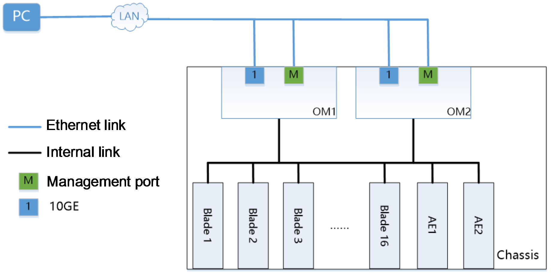
Table 3 Description for network information configuration
|
Device |
IP address |
Username/Password |
|
OM management software |
· Management IP addresses: 192.168.100.101/24 · Gateway: 192.168.100.254/24 |
· Username (default): admin · Password (default): Password@_ |
|
FIST management software |
· Management IP addresses (default): 192.168.0.100/24 · Gateway: 192.168.0.254/24 |
· Username (default): admin · Password (default): Password@_ |
|
PC |
IP addresses: 192.168.100.1/24 |
N/A |
|
AE module |
· IP address of primary AE module: 192.168.17.100/24 · IP address of backup AE module: 192.168.17.101/24 · Virtual IP address for iSCSI: 172.16.20.222/24 |
N/A |
Analysis
· To transmit management traffic, connect the B16000 blade chassis to the network through a management port of the OM module.
· To transmit FIST service traffic, connect the 10GE fiber interface 1 of the OM module to the network.
· To improve the networking availability and ensure link redundancy, measures below are taken in this example:
¡ Set up an AE primary/backup cluster with two AE modules.
¡Configure two OM modules, and run them in the primary/backup mode.
Software versions used
The configuration example was created and verified on FIST-2.00.24 of FIST management software.
Configuration procedure
Connecting OM module cables
1. Connect management ports of the two OM modules and the 10GE optical interface in the chassis to the network. The external interface of the OM module is shown in Figure 5, and the interface description is shown in Table 4.
Figure 5 External interface of OM module
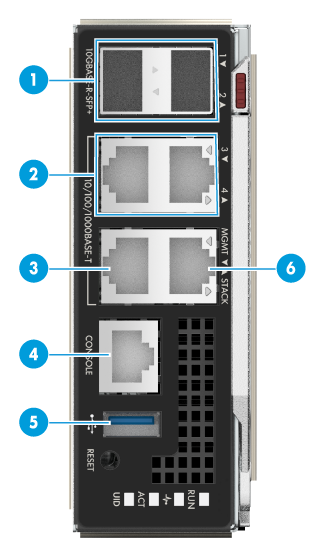
Table 4 Description of external interfaces
|
SN |
Interface name |
Type |
Quantity |
Remarks |
|
1 |
10 GE optical interface |
SFP+ |
2 |
Interfaces of OM module service plane |
|
2 |
GE copper port |
RJ-45 |
2 |
Interfaces of OM module service plane |
|
3 |
Management interface (MGMT) |
RJ-45 |
1 |
For chassis management |
|
4 |
Console port |
RJ-45 |
1 |
For OM module commissioning system or remote management |
|
5 |
USB3.0 interface |
Standard USB 3.0 |
1 |
For connecting USB device |
|
6 |
Cascading interface STACK |
RJ-45 |
1 |
For chassis cascading |
2. Power on the B16000 blade chassis, and start FIST. After FIST is started, the system will automatically add the chassis of the AE module.
Logging in to FIST
1. Open a browser on your PC, type http://192.168.0.100 in the address bar, and press the Enter key to open the FIST login interface.
2. Enter the FIST username (admin) and the password (Password@_) on the login interface, and click the Login button, to navigate to the FIST Management home page.
3. On the FIST interface, click Menu > Device Management > Chassis List to view chassis list information and ensure the chassis is added to FIST and is in good condition. The chassis has been correctly added.
Creating AE primary/backup cluster
1. Click Menu > System Management > Cluster Management to navigate to the cluster management page.
2. Click the Create Cluster link, and enter relevant information in the popup box.
Table 5 Creating cluster parameter
|
Parameter |
Remarks |
IP address |
|
IP address of primary/backup node |
IP address of primary/backup AE module when the cluster is created |
For primary node: 192.168.17.100/24 For backup node: 192.168.17.101/24 |
|
Virtual IP address for FIST |
IP address for accessing FIST after a cluster is set up |
192.168.0.100/24 |
|
Virtual IP address for iSCSI |
This virtual IP address for iSCSI is used for configuring relevant iSCSI service after the cluster is set up. |
172.16.20.222/24 |
3. Click the OK button to start creating a cluster. After the cluster is created, FIST will automatically reboot. After rebooting, log in with the virtual IP address for FIST.
4. The cluster is created when the primary and backup node information and their statuses are displayed.
Verifying the configuration
|
|
NOTE: · Please see FIST User Guide for profile preparation before installing operating systems in batches. · If you have installed the operating systems for existing blade servers, you may export image clones and applied them to Profile. See FIST User Guide for operation steps and restrictions of image clones. |
This section describes how to install operating systems in blade servers by using the server configuration templates, and how to configure and verify achieved networking requirements. Please ensure Profile is ready before operation.
1. Click Menu > Server Deployment > Profile Application to navigate to the Profile operation page.
2. Select all blade servers, click the Apply Profile button, apply Profile to all blade servers in the chassis in batches, and install the Red Hat Enterprise Linux 7.5 (64-bit) operating system.
3. On the popped-up Profile dialog box, select a Profile file, check "I have read operation tips for server configuration templates", and click OK to apply Profile.
4. Operating systems have been installed on all blade servers displayed on the FIST page.
5. Log in to one blade server to verify, check, and verify that the operating system has been installed.
Example: Configuring multi-chassis management through OM module links
Network requirement
As shown in Figure 6, two H3C Uniserver B16000 blade chassis (Chassis 1 and Chassis 2) are connected with external cables, with the following components installed:
· One AE module, with the pre-installed FIST management software, is respectively installed in the slots E1 and E2 in Chassis 1.
· Blade servers are installed in slots Blade 1 to 16 of the two chassis. In this example, the blade server is H3C UniServer B5700 G3.
· OM modules are installed for the slot 1 and slot 2 in the two chassis.
The current requirement is to manage all blade servers in the two chassis in batches with FIST, for example, install operating systems in batches. FIST service traffic is transmitted through the OM module links, and link redundancy is ensured through the primary/backup OM module and AE primary/backup cluster.
Figure 6 Networking for multi-chassis management through OM module
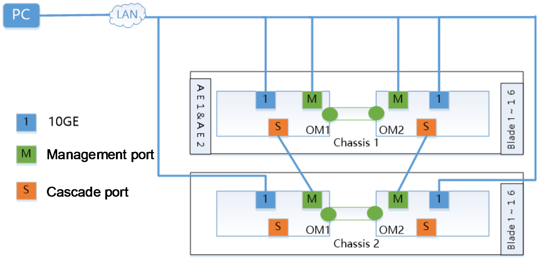
Table 6 Description for network information configuration
|
Device |
IP address |
Username/password |
|
OM management software for Chassis 1 |
· Management IP addresses: 192.168.100.100/24 · Gateway: 192.168.100.254/24 |
· Username (default): admin · Password (default): Password@_ |
|
OM management software for Chassis 2 |
· Management IP addresses: 192.168.100.101/24 · Gateway: 192.168.100.254/24 |
· Username (default): admin · Password (default): Password@_ |
|
FIST management software |
· Management IP addresses (default): 192.168.0.100/24 · Gateway: 192.168.0.254/24 |
· Username (default): admin · Password (default): Password@_ |
|
PC |
IP addresses: 192.168.100.1/24 |
N/A |
|
AE module |
· IP address of primary AE module: 192.168.17.100/24 · IP address of backup AE module: 192.168.17.101/24 · Virtual IP address for iSCSI: 172.16.20.222/24 |
N/A |
Analysis
· To transmit management traffic, connect the B16000 blade chassis to the network through a management port of the OM module.
· To transmit FIST service traffic, connect the 10GE fiber interface 1 of the OM module to the network.
· To simultaneously manage two chassis and all blade servers with the FIST management software, dual-channel cascading is used.
· To improve the networking availability and ensure link redundancy, measures below are taken in this example:
¡ Set up an AE primary/backup cluster with two AE modules.
¡Configure two OM modules, and run them with the primary/backup mode.
¡To recommended cascading failure due to a single point of failure, dual-channel cascading is recommended for use.
Software versions used
The following information was created and verified on FIST-2.00.24 of FIST management software.
Configuration procedure
Configuring dual-channel cascading
In this example, Chassis 1 acts as the primary chassis, and Chassis 2 serves as the backup chassis. By taking the dual-channel cascading of the two chassis for example, the procedures are as follows:
1. Connect management ports of the two OM modules and the 10GE optical interface in the chassis to the network. The external interface of the OM module is shown in Figure 7, and the interface description is shown in Table 7.
Figure 7 External OM module interfaces

Table 7 Description of external interfaces
|
SN |
Interface name |
Type |
Quantity |
Remarks |
|
1 |
10 GE optical interface |
SFP+ |
2 |
Interfaces of OM module service plane |
|
2 |
GE copper port |
RJ-45 |
2 |
Interfaces of OM module service plane |
|
3 |
Management interface (MGMT) |
RJ-45 |
1 |
For chassis management |
|
4 |
Console port |
RJ-45 |
1 |
For OM module commissioning system or remote management |
|
5 |
USB3.0 interface |
Standard USB 3.0 |
1 |
For connecting USB device |
|
6 |
Cascading interface STACK |
RJ-45 |
1 |
For chassis cascading |
2. Connect the cascading interface in Chassis 1 OM 1 to the management interface in Chassis 2 OM 1, and connect the cascading interface in Chassis 1 OM 2 to the management interface in Chassis 2 OM 2 to finish cascading of the two chassis.
Adding two chassis with FIST
1. Power on the B16000 blade chassis, and start FIST. After FIST is started, the system will automatically add the chassis of the AE module and the chassis cascaded to it.
2. Open a browser on your PC, type http://192.168.0.100 in the address bar, and press the Enter key to open the FIST login interface.
3. Enter the FIST username (admin) and the password (Password@_) on the login interface, and click the Login button, to navigate to the FIST Management home page.
4. On the FIST interface, click Menu > Device Management > Chassis List to view chassis list information. The chassis has been correctly added.
Creating AE primary/backup cluster
1. Click Menu > System Management > Cluster Management menus to navigate to the cluster management page.
2. Click the Create Cluster link, and enter relevant information in the popup box.
Table 8 Creating cluster parameter
|
Parameter |
Remarks |
IP address |
|
IP address of primary/backup node |
IP address of primary/backup AE module when the cluster is created |
For primary node: 192.168.17.100/24 For backup node: 192.168.17.101/24 |
|
Virtual IP address for FIST |
IP address for accessing FIST after a cluster is set up |
192.168.0.100/24 |
|
Virtual IP address for iSCSI |
This virtual IP address for iSCSI is used for configuring relevant iSCSI service after the cluster is set up. |
172.16.20.222/24 |
3. Click the OK button to start creating a cluster. After the cluster is created, FIST will automatically reboot. After rebooting, log in with the virtual IP address for FIST.
4. The cluster is created when the primary and backup node information and their statuses are displayed.
CVerifying the configuration
|
|
NOTE: · Please see FIST User Guide for profile preparation before installing operating systems in batches. · If you have installed the operating systems for existing blade servers, you may export image clones and applied them to Profile. See FIST User Guide for operation steps and restrictions of image clones. |
This section describes how to install operating systems in batches for blade servers, and how to configure and verify achieved networking requirements. Please ensure Profile is ready before operation.
1. Click Menu > Server Deployment > Profile Application to navigate to the Profile operation page.
2. Select all blade servers, click the Apply Profile button, apply Profile to all blade servers in the two chassis in batches, and install the Red Hat Enterprise Linux 7.5 (64 bit) operating system.
3. On the popped-up Profile dialog box, select a Profile file, check "I have read operation tips for server configuration templates", and click OK to apply Profile.
4. Operating systems have been installed on all blade servers displayed on the FIST page.
5. Log in to one blade server to verify, check, and confirm the operating system has been installed.
Example: Configuring multi-chassis management through ICM module links
Network requirement
As shown in Figure 8, the following components are installed in two H3C Uniserver B16000 chassis (Chassis A and Chassis B):
· One AE module, with the pre-installed FIST management software, is respectively installed in the slots E1 and E2 in Chassis A.
· One ICM module is respectively installed in each of slots ICM 1 and ICM 4 in Chassis A and Chassis B.
· Blade servers are respectively installed in slots Blade 1 to 16 of Chassis A and Chassis B.
· An Ethernet Mezz network adapter is installed in the slot Mezz1 in each blade server.
· The two ICM modules are respectively connected to XGE1/0/49 and XGE1/0/50 of TOR switches through their respective XGE1/1/9 interfaces.
In this example, the blade server is H3C UniServer B5700 G3, the Mezz network adapter is NIC-ETH521i-Mb-4*10G (hereinafter referred to as ETH521i), the ICM module is the BX720E switch module, and the TOR switch is the H3C S6800-32Q Ethernet switch.
The current requirement is to manage all blade servers in Chassis A and Chassis B can be managed with the FIST management software in the AE module of Chassis A, transmit FIST service traffic only through the ICM module links, isolate traffic to avert interference to other service traffic, set up IRF and AE primary/backup clusters through switches to ensure link redundancy, and install operating systems in batches for all blade servers in a network through the FIST service network.
Figure 8 Networking for multi-chassis management through ICM module
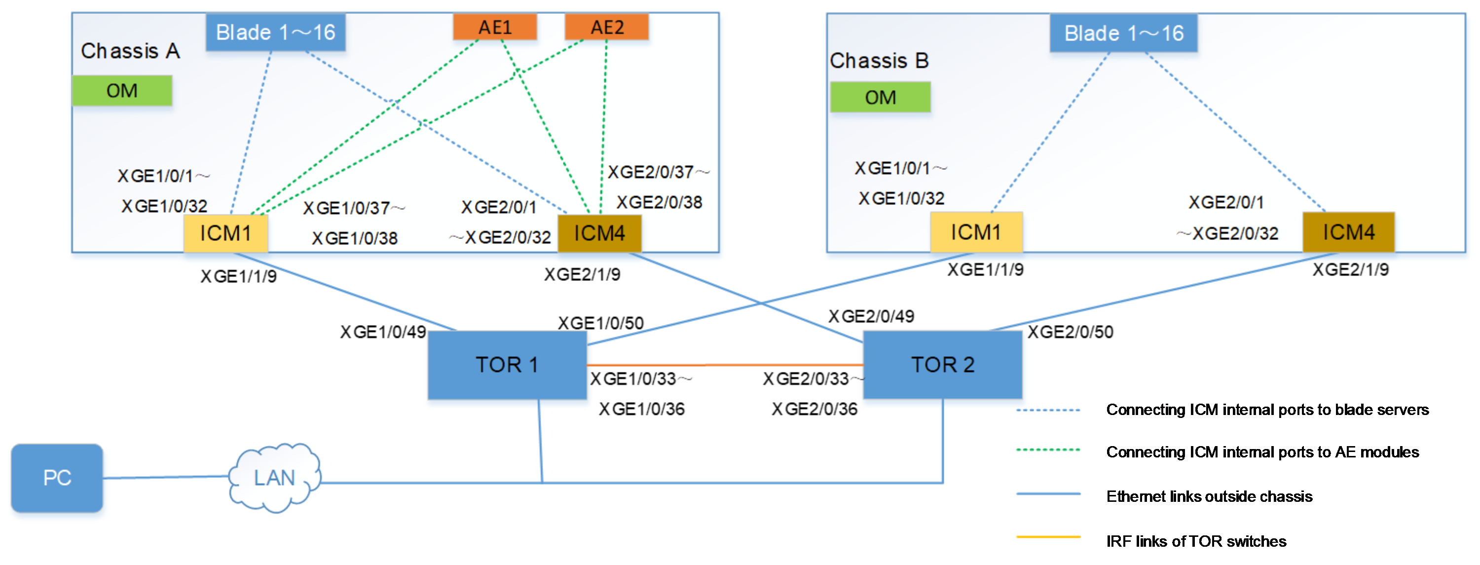
Table 9 Description for network information of multi-chassis management (through ICM module)
|
Device |
IP address |
Username/password |
|
PC |
IP addresses: 192.168.100.1/24 |
N/A |
|
FIST management software |
· Management IP addresses (default): 192.168.0.100/24 · Gateway: 192.168.0.254/24 |
· Username (default): admin · Password (default): Password@_ |
|
Chassis A OM management software |
· Management IP addresses (default): 192.168.100.100/24 · Gateway: 192.168.100.254/24 |
· Username (default): admin · Password (default): Password@_ |
|
Chassis B OM management software |
· Management IP addresses (default): 192.168.100.101/24 · Gateway: 192.168.100.254/24 |
· Username (default): admin · Password (default): Password@_ |
|
AE module |
· IP address of primary AE module: 192.168.17.100/24 · IP address of backup AE module: 192.168.17.101/24 · Virtual IP address for iSCSI: 172.16.20.222/24 |
N/A |
Analysis
· To ensure all blade servers in Chassis A and Chassis B can be managed through the FIST management software in the AE module in Chassis B and the FIST service traffic is transmitted through the ICM module links, connect ICM modules of Chassis A and Chassis B to the same network, that is, both connected to the same TOR switch in this example. Moreover, the communication is in good condition.
· To ensure the FIST service traffic is transmitted only through ICM module links rather than OM links, isolate the OM module from the FIST service network, that is, the OM service ports in two chassis cannot be connected to the FIST service network.
· To ensure the FIST service network bandwidth is adequate, the TOR switch must support a rate of 10 Gbps or more. Therefore, the H3C S6800-32Q Ethernet switch is used in this example.
· To ensure the FIST service traffic is isolated from other service traffic, create VLAN 2 in the network, and add the ICM modules and switch in the network to VLAN 2.
· To improve the networking availability and ensure link redundancy, measures below are taken in this example:
¡ Creating AE primary/backup cluster
¡ Two ICM modules, configured in each chassis, are connected to TOR switches
¡ IRF is configured between two TOR switches.
Software versions used
This example was configured and verified on the following versions:
· FIST: FIST-2.00.24
· ICM: SWITCH_SYS-1.02.03
· TOR switch: S6800-CMW710-R2702
Configuration procedure
Logging in to FIST
1. Open a browser on your PC, type http://192.168.0.100 in the address bar, and press the Enter key to open the FIST login interface.
2. Enter the FIST username (admin) and the password (Password@_) on the login interface, and click the Login button, to navigate to the FIST Management home page.
Creating AE primary/backup cluster
1. Click Menu > System Management > Cluster Management menus to navigate to the cluster management page.
2. Click the Create Cluster link, and enter relevant information in the popup box.
Table 10 Creating cluster parameter
|
Parameter |
Remarks |
IP address |
|
IP address of primary/backup node |
IP address of primary/backup AE module when the cluster is created |
For primary node: 192.168.17.100/24 For backup node: 192.168.17.101/24 |
|
Virtual IP address for FIST |
IP address for accessing FIST after a cluster is set up |
192.168.0.100/24 |
|
Virtual IP address for iSCSI |
This virtual IP address for iSCSI is used for configuring relevant iSCSI service after the cluster is set up. |
172.16.20.222/24 |
3. Click the OK button to start creating a cluster. After the cluster is created, FIST will automatically reboot. After rebooting, log in with the virtual IP address for FIST.
4. The cluster is created when the primary and backup node information and their statuses are displayed.
Adding two chassis with FIST
1. As the chassis of the AE module will be automatically added to FIST, Chassis A will be automatically added to FIST.
2. Manually add a chassis different to that of the AE module. In this example, Chassis B is manually added to FIST.
a. On the FIST interface, click Menu > Device Management > Chassis List.
b. Click the Add Chassis button, and enter the management IP address (192.168.101.101) of the OM module in Chassis B, username (admin), and the password (Password@_) in the popped-up dialog box. Click OK to complete the operation.
3. On the FIST interface, click Menu > Device Management > Chassis List to view chassis list information. The chassis has been correctly added.
Checking hardware configuration with FIST
As operating systems are installed in batches for multiple blade servers with the FIST management software in this example, the hardware in the networking shall be in good condition. Hardware configuration can be confirmed with FIST through procedures below:
1. Log in to FIST.
2. Verify that chassis and blade servers in the network are in good condition, and ICM modules in the slots 1 and 4 are in place.
3. Check network adapter status of blade server. Navigate to the Blade Server Details > Node Interconnection page, and verify that if the NIC-ETH521i-Mb-4*10G network adapter is in slot Mezz 1, and if the connecting status between the network adapter port and the ICM module port card is "up".
4. Check the connecting statuses of the AE modules and the ICM modules. Navigate to the System Management > Network Setting page, and verify that if the AE module network adapter port is "UP".
Connecting ICM modules to TOR switches
To improve networking availability, ensure link redundancy. Respectively connect ICM modules in each chassis to different TOR switches:
· Respectively connect ICM 1 in each of Chassis A and Chassis B, through their respective XGE 1/1/9 interfaces, to XGE 1/0/49 and XGE 1/0/50 of TOR switch A.
· Respectively connect ICM 4 in each of Chassis A and Chassis B, through their respective XGE 2/1/9 interfaces, to XGE 2/0/49 and XGE 1/0/50 of TOR switch B.
Configuring the interconnect module
Configure ICM modules in Chassis A and Chassis B.
1. Create VLAN 2, and connect ICM 1 and the AE module in Chassis A to the blade server.
# Create VLAN 2.
[H3C] vlan2
# Add all internal ports GigabitEthernet1/0/1 to GigabitEthernet1/0/38 to VLAN 2.
[H3C-vlan2] port gigabitethernet 1/0/1 to gigabitethernet 1/0/38
# Add external ports GigabitEthernet1/1/9, connected to TOR, to VLAN 2.
[H3C-vlan2] port gigabitethernet 1/1/9
2. Add ICM 1 in Chassis A and ICM 1 and ICM 4 in Chassis B to VLAN 2 in the same manner.
3. Save the configuration.
# Save the configuration.
[H3C] save
The current configuration will be written to the device. Are you sure? [Y/N]:y
Please input the file name(*.cfg)[flash:/startup.cfg]
(To leave the existing filename unchanged, press the enter key):
Configuring an TOR switch
Configure an IRF
To improve networking availability, ensure link redundancy. Set up IRF with two TOR switches.
· Configure TOR1
# Select IRF physical ports and disable them. For easy configuration, these physical ports are disabled and enabled with the configuring interfaces in batches.
<H3C> system-view
[H3C] interface range Ten-GigabitEthernet 1/0/33 to Ten-GigabitEthernet 1/0/36
[H3C-if-range] shutdown
# Configure the IRF port 1/2, and bind it to the physical ports Ten-GigabitEthernet 1/0/33 to Ten-GigabitEthernet 1/0/36.
[H3C] irf-port 1/2
[H3C-irf-port1/2] port group interface Ten-GigabitEthernet 1/0/33
[H3C-irf-port1/2] port group interface Ten-GigabitEthernet 1/0/34
[H3C-irf-port1/2] port group interface Ten-GigabitEthernet 1/0/35
[H3C-irf-port1/2] port group interface Ten-GigabitEthernet 1/0/36
[H3C-irf-port1/2] quit
# Enable the physical ports Ten-GigabitEthernet 1/0/33 to Ten-GigabitEthernet 1/0/36, and save the configuration.
[H3C] interface range Ten-GigabitEthernet 1/0/33 to Ten-GigabitEthernet 1/0/36
[H3C-if-range] undo shutdown
[H3C-if-range] quit
# Configure the IRF role with high priority, with the priority of serving as a primary device, activate configurations under the IRF ports, and save the configuration.
[H3C] irf member 1 priority 10
[H3C] save
The current configuration will be written to the device. Are you sure? [Y/N]:y
Please input the file name(*.cfg)[flash:/startup.cfg]
(To leave the existing filename unchanged, press the enter key):
# Activate configurations under the IRF ports.
[H3C] irf-port-configuration active
· Configure TOR2
# Set TOR2 device member number to be 2, and reboot the device to validate such number.
<H3C> system-view
[H3C] irf member 1 renumber 2
Renumbering the member ID may result in configuration change or loss. Continue? [Y/N]:y
[H3C] quit
<H3C> save
The current configuration will be written to the device. Are you sure? [Y/N]:
Before pressing ENTER you must choose 'YES' or 'NO'[Y/N]:y
Please input the file name(*.cfg)[flash:/startup.cfg]
(To leave the existing filename unchanged, press the enter key):
flash:/startup.cfg exists, overwrite? [Y/N]:y
Validating file. Please wait...
Saved the current configuration to mainboard device successfully.
<H3C> reboot
# Log in to the device again, select the IRF physical ports, and disable them. For easy configuration, these physical ports are disabled and enabled with the configuring interfaces in a batch.
<H3C> system-view
[H3C] interface range Ten-GigabitEthernet 2/0/33 to Ten-GigabitEthernet 2/0/36
[H3C-if-range] shutdown
# Configure the IRF port 2/1, and bind it to the physical port Ten-GigabitEthernet 2/0/33 to Ten-GigabitEthernet 2/0/36.
[H3C] irf-port 2/1
[H3C-irf-port2/1] port group interface Ten-GigabitEthernet 2/0/33
[H3C-irf-port2/1] port group interface Ten-GigabitEthernet 2/0/34
[H3C-irf-port2/1] port group interface Ten-GigabitEthernet 2/0/35
[H3C-irf-port2/1] port group interface Ten-GigabitEthernet 2/0/36
[H3C-irf-port2/1] quit
# Enable the physical ports Ten-GigabitEthernet 2/0/33 to Ten-GigabitEthernet 2/0/36, and save the configuration.
[H3C] interface range Ten-GigabitEthernet 2/0/33 to Ten-GigabitEthernet 2/0/36
[H3C-if-range] undo shutdown
[H3C-if-range] quit
[H3C] save
The current configuration will be written to the device. Are you sure? [Y/N]:y
Please input the file name(*.cfg)[flash:/startup.cfg]
(To leave the existing filename unchanged, press the enter key):
# Activate configurations under the IRF ports.
[H3C] irf-port-configuration active
# After the ICM modules are rebooted, view IRF information, and confirm that IRF has been set up.
[H3C] display irf
MemberID Role Priority CPU-Mac Description
*+1 Master 10 00e0-fc0f-8c02 ---
2 Standby 1 00e0-fc0f-8c03 ---
--------------------------------------------------
* indicates the device is the master.
+ indicates the device through which the user logs in.
Configure an VLAN
# Create VLAN 2.
[H3C] vlan2
[H3C-vlan2]quit
# Create a layer-2 aggregation port, add the physical ports to the aggregation group, and allow VLAN 2 to pass.
[H3C] int Bridge-Aggregation 10
[H3C-Bridge-Aggregation10]
[H3C] interface Ten-GigabitEthernet 1/0/49
[H3C-Ten-GigabitEthernet1/0/49] port link-aggregation group 10
[H3C-Ten-GigabitEthernet1/0/49] quit
[H3C] interface Ten-GigabitEthern 1/0/50
[H3C-Ten-GigabitEthernet1/0/50] port link-aggregation group 10
[H3C-Ten-GigabitEthernet1/0/50] quit
[H3C] int Bridge-Aggregation 10
[H3C-Bridge-Aggregation10] port link-type trunk
[H3C-Bridge-Aggregation10] port trunk permit vlan 2
[H3C-Bridge-Aggregation10] undo port trunk permit vlan 1
[H3C-Bridge-Aggregation10] quit
# You can view the information about the aggregation port and confirm that the aggregation port has been created.
[H3C] display link-aggregation verbose Bridge-Aggregation 10
Loadsharing Type: Shar -- Loadsharing, NonS -- Non-Loadsharing
Port Status: S -- Selected, U -- Unselected, I -- Individual
Port: A -- Auto port, M -- Management port, R -- Reference port
Flags: A -- LACP_Activity, B -- LACP_Timeout, C -- Aggregation,
D -- Synchronization, E -- Collecting, F -- Distributing,
G -- Defaulted, H -- Expired
Aggregate Interface: Bridge-Aggregation10
Aggregation Mode: Static
Loadsharing Type: Shar
Management VLANs: None
Port Status Priority Oper-Key
XGE1/0/49 S 32768 1
XGE1/0/50 S 32768 1
# Create a VLAN port and set the IP address of the port to 100.1.1.1/24.
[H3C] interface vlan 2
[H3C-Vlan-interface2] ip address 100.1.1.1 255.255.255.0
[H3C-Vlan-interface2] quit
# Check the status of VLAN 2 port and confirm that the port is UP.
[H3C-Vlan-interface2]display interface vlan 2 brief
Brief information on interfaces in route mode:
Link: ADM - administratively down; Stby - standby
Protocol: (s) - spoofing
Interface Link Protocol Primary IP Description
Vlan2 UP UP 100.1.1.1
# Save the configuration.
[H3C] save
The current configuration will be written to the device. Are you sure? [Y/N]:y
Please input the file name(*.cfg)[flash:/startup.cfg]
(To leave the existing filename unchanged, press the enter key):
Verifying the configuration
|
|
NOTE: · Please see FIST User Guide for profile preparation before installing operating systems in batches. · If you have installed the operating systems for existing blade servers, you may export image clones and applied them to Profile. See FIST User Guide for operation steps and restrictions of image clones. |
This section describes how to install operating systems in batches for blade servers, and how to configure and verify achieved networking requirements. Please ensure Profile is ready before operation.
1. Click Menu > Server Deployment > Profile Application menus to navigate to the Profile operation page.
2. Select all blade servers, click the Apply Profile button, apply Profile to all blade servers in the chassis in batches, and install the Red Hat Enterprise Linux 7.5 (64-bit) operating system.
3. On the popped-up Profile dialog box, select a Profile file, check "I have read operation tips for server configuration templates", and click OK to apply Profile.
4. Operating systems have been installed on all blade servers displayed on the FIST page.
5. Log in to one blade server to verify, check, and confirm the operating system has been installed.
Comparison of networking verification results
This section describes the duration of installing clone operating systems in batches through FIST in each application scenario.
Managing multi-chassis node through OM module links
Actual verification data of each networking mode is shown in Table 11.
Table 11 Actual test data statistics of different networking modes
|
No. |
Networking |
AE primary/backup clusters in the same chassis |
Primary/backup AE module switch |
Configuration description |
Blade server quantity |
Duration (min) |
|
1 |
A single chassis |
Y |
N |
N/A |
16 |
5–10 |
|
2 |
A single chassis |
Y |
Y |
N/A |
16 |
5–10 |
|
3 |
Multi-chassis and dual-channel cascading |
Y |
N |
· Chassis A: 16 blade servers and 2 AE modules are in the same chassis. · Chassis B: cascaded to Chassis A |
16 |
5–10 |
|
4 |
Multi-chassis and dual-channel cascading |
N |
N |
Primary/backup AE modules and blade servers are in the same chassis |
16 |
7–10 |
|
5 |
Multi-chassis and dual-channel cascading |
N |
Y |
· Chassis A: 16 blade servers and a primary AE module · Chassis B: with a backup AE module, cascaded to Chassis A |
16 |
7–10 |
|
6 |
Multi-chassis and dual-channel cascading |
N |
N |
AE primary/backup clusters and blade servers are not in the same chassis. |
8 |
7–9 |
|
7 |
Multi-chassis and dual-channel cascading |
N |
Y |
AE primary/backup clusters and blade servers are not in the same chassis. |
15 |
7–9 |
|
8 |
Multi-chassis and dual-channel cascading |
Y |
N |
Primary/backup AE modules and blade servers are in the same chassis |
15 |
7–9 |
|
9 |
Multi-chassis and dual-channel cascading |
N |
N |
Primary/backup AE modules and blade servers are in the same chassis |
8 |
7–9 |
Managing multi-chassis node through ICM module links
Install operating systems on blade servers in another chassis through the ICM modules in the chassis of the AE modules. The actual test data of each networking is shown in Table 12.
Table 12 Managing test data of multi-chassis node through ICM module links
|
SN |
Primary/backup AE module switch |
Availability of both primary and backup ICM modules and forming of a dual-channel |
Blade server quantity |
Duration (min) |
|
1 |
N |
N |
16 |
8–11 |
|
2 |
Y |
N |
16 |
8–11 |
|
3 |
N |
Y |
16 |
8–13 |
|
4 |
Y |
Y |
16 |
8–13 |
