- Table of Contents
-
- H3C UniServer B16000 Blade Server Configuration Examples-6W100
- 01-FC and FCoE Services Configuration Examples
- 02-Ethernet Services Configuration Examples
- 03-Virtual Management Network Configuration Examples
- 04-Shared Storage Configuration Examples
- 05-VC Configuration Examples
- 06-Chassis Profile Configuration Examples
- 07-IB Service Configuration Examples
- 08-Blade Server FIST Configuration Examples
- Related Documents
-
| Title | Size | Download |
|---|---|---|
| 02-Ethernet Services Configuration Examples | 3.78 MB |
Contents
Example: Configuring Ethernet services
Configuring the mezzanine card
Configuring the interconnect module
Configuring the aggregation switch
Example: Configuring Ethernet services (pass-through module)
Configuring the mezzanine card
Example: Configuring Ethernet services (monitor link)
Configuring the mezzanine card
Configuring the interconnect module
Configuring the aggregation switch
Verifying the configuration under the Linux system
Verifying the configuration under the Windows system
Introduction
The following information provides examples for configuring Ethernet services for the H3C UniServer B16000 blade server chassis.
Hardware compatibility
Table 1 lists the hardware to be used in typical networking modes. If there are multiple models in a cell, the hardware of these models is appropriate for this configuration.
Table 1 Hardware compatibility
|
Configuration example |
Hardware compatibility |
|||
|
NIC |
Interconnection module |
External switch |
Backend storage |
|
|
Example: Configuring Ethernet services (switch module) |
· ETH521i · ETH522i · ETH561i · ETH640i · ETH681i · ETH682i |
· BX720EF · BX720E · BX1010E · BX1020EF |
Ethernet switch |
- |
|
Example: Configuring Ethernet services (pass-through module) |
· ETH521i · ETH522i · ETH561i · ETH640i · ETH681i · ETH682i |
· BT616E · BT1004E |
Ethernet switch |
- |
|
Example:P Configuring Ethernet services (monitor link) |
· ETH521i · ETH522i · ETH561i · ETH640i · ETH681i · ETH682i |
· BX720EF · BX720E · BX1010E · BX1020EF |
Ethernet switch |
- |
Prerequisites
The configuration examples were created and verified in a lab environment, and all the devices were started with the factory default configuration. When you are working on a live network, make sure you understand the potential impact of every command on your network.
The following information is provided based on the assumption that you have basic knowledge of Ethernet, port aggregation features, H3C blade servers, interconnect modules, and Windows/Linux/ESXi/CAS operating systems.
The following information mainly describes the procedure for configuring the blade server chassis. As a best practice, configure external network settings as needed.
Example: Configuring Ethernet services
Network requirement
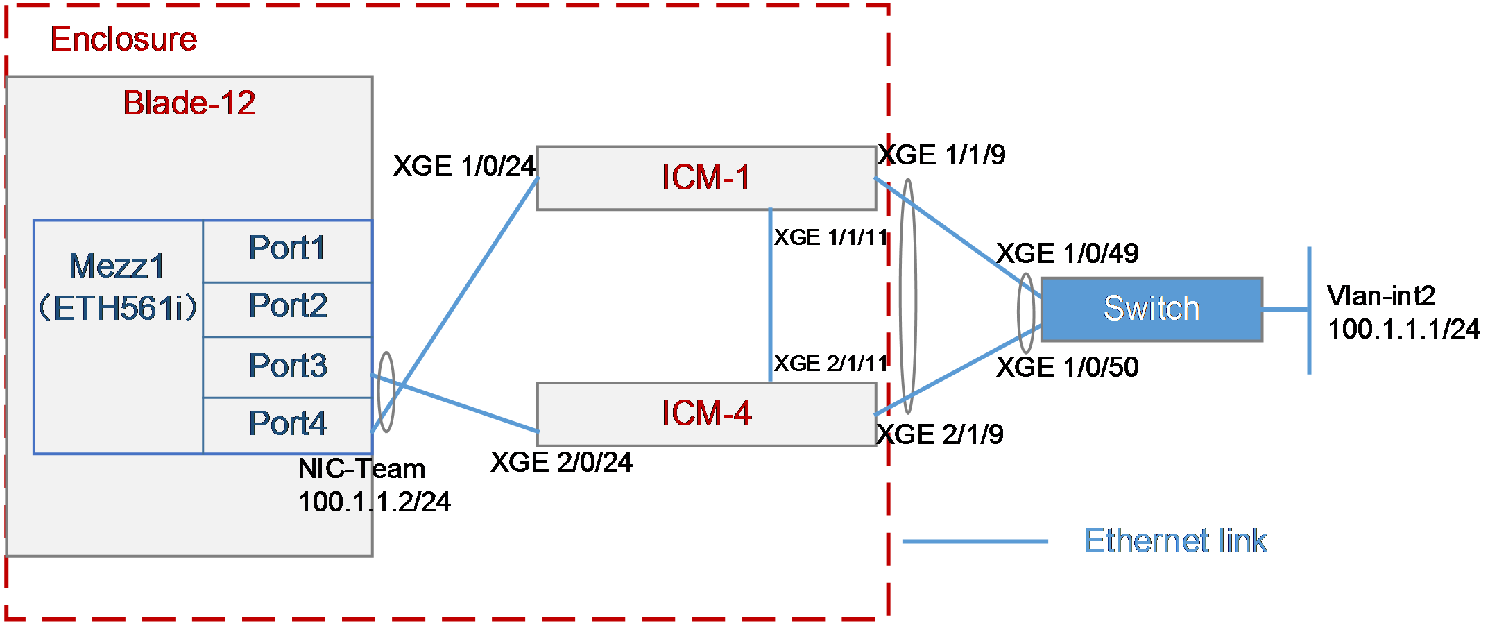
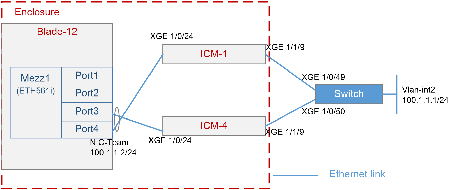
As shown in Figure 1, the blade server and interconnect modules are installed in the H3C B16000 blade server chassis. The blade server is installed in slot 12, two interconnect modules are installed in slot 1 and slot 4, and the mezzanine card is installed in the mezzanine card slot 1 of the blade server. The XGE 1/1/9 port of each of the two interconnect modules is connected to the XGE 1/0/49 and XGE 1/0/50 ports of the Ethernet switch.
In this example, the following devices and modules are used: mezzanine card (NIC-ETH561i-Mb-4*10G, "ETH561i"), aggregation interconnect module (BX720E), Ethernet switch (H3C switch).
It is required that the OS on the blade server can access the external Ethernet network through the switch (in this example, accessing VLAN 2 port on the switch is used as an example), and can still communicate correctly when any interconnect module fails.
Figure 1 Example: Configuring Ethernet services
Analysis
· To improve the reliability of external links, you need to aggregate the links over the uplink port on the interconnect module and the downlink port on the aggregation switch.
· To improve the reliability of internal links in the blade server chassis, you need to configure the bonding function under the OS to bind Port 3 and Port 4 of the mezzanine card to a logic port. In this example, the bonding function adopts the active/standby mode.
· In this example, the bonding function adopts the active/standby mode, indicating that either Port 3 or Port 4 on the mezzanine card receives and sends the traffic, while the other serves as the backup. Therefore, you do not need to aggregate the links over the XGE 1/0/24 internal ports of the two interconnect module. If the bonding function uses other modes, you need to aggregate the links over the internal ports of the two interconnect modules.
· As a best practice, disable the STP function of the internal ports on the interconnect modules, to prevent the rebooting or plugging in/out of the blade server from causing the STP of the interconnect modules to start calculating and resulting in short disconnection of external ports on the interconnect modules.
Software versions used
This example was created and verified on SWITCH_SYS-1.00.11 and OM-1.00.11 versions.
Configuration precautions
Make sure that the OS can recognize the ETH561i network adapter correctly. If it cannot, install the network adapter driver according to the ETH561i Mezzanine Card Module User Guide.
Configuration procedure
Querying port information
Query the correspondence among mezzanine cards, internal ports of interconnect modules, and network adapters under the OS according to "Querying port relations."
It can be learned that:
· In this example, Port 3 and Port 4 of mezzanine card 1 are used and are named ens5f2 and ens5f3 under the OS, respectively.
· Ten-gigabitethernet 1/0/24 ports of interconnect modules 1 and 4 are used in this example.
Configuring the mezzanine card
The following information describes the procedure for configuring Linux and Windows operating systems on the blade server.
Procedure for configuring Linux
|
|
NOTE: The following information provides the procedure for configuring the bonding function under Red Hat 7.5. |
1. Configure the bonding function of ens5f2 and ens5f3 ports
a. Execute the nmtui command to start the network adapter configuration tool that comes with the system.
[root@localhost]# nmtui
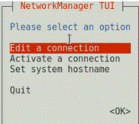
b. Select Edit a connection to edit the network connection, as shown in Figure 2.
Figure 2 Selecting Edit a connection

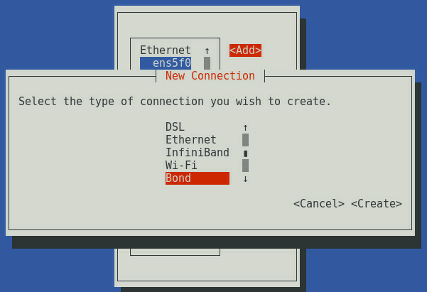
c. Select Add to add a new network connection, select the type of connection as Bond, and click Create, as shown in Figure 3.
Figure 3 Adding a "bond" connection
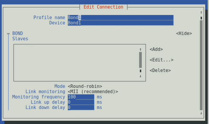
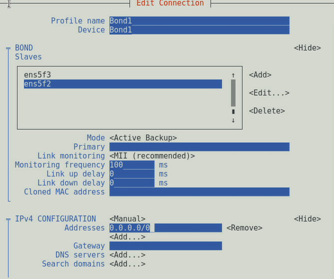
d. As shown in Figure 4, set Profile name and Device.
Figure 4 Setting the bond connection
e. Under the BOND Slaves option, select Add and add ens5f2 and ens5f3 slave ports, as shown in Figure 5.
f. Set Mode to Active Backup and set the IP address according to the service environment. In this example, the service traffic is transmitted through the VLAN port connected to the bond port. Therefore, set the static IP address of the bond master port to 0.0.0.0/0, as shown in Figure 6.
Figure 6 Setting network parameters
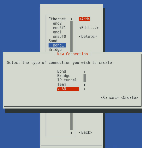
g. Return to the homepage of the nmtui tool, select Add to add a new network connection, select the type of connection as VLAN, and click Create, as shown in Figure 7.
h. As shown in Figure 8, set Profile name, Device and VLAN id, and configure the IP address of the service network. This example uses the VLAN ID of 2 and the static IP address 100.1.1.2/24.
Figure 8 Setting the IP address of the VLAN slave port connected to the bond port

i. Then, press Esc to return to the configuration screen.
2. Execute the systemctl restart network command to restart the network service.
[root@localhost]# systemctl restart network
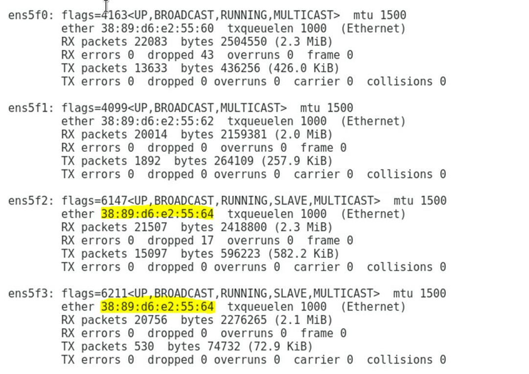
3. Execute the ifconfig command to view the Bond1 and Bond1.2 configurations as shown in Figure 9 and Figure 10. Note that the physical addresses of the aggregation port and the two physical network adapters are the same in the active/standby mode.
Figure 9 Viewing the network adapter configuration (I)
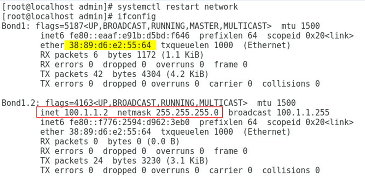
Figure 10 Viewing the network adapter configuration (II)
Procedure for configuring Windows
|
|
NOTE: The following information provides the procedure for configuring NIC teaming function on the Windows Server. The Windows Server 2016 is used as an example. |
1. Check the correspondence of network adapter ports.
Query the correspondence among mezzanine cards, internal ports of interconnect modules, and network adapters of the OS according to "Querying port relations." In this example, Port 3 and Port 4 of mezzanine card 1 are used and are named Ethernet4 and Ethernet6 under the OS, respectively.
2. Configure the teaming.
a. As shown in Figure 11, click Disabled in Server Manager > Local Server > NIC Teaming to open the configuration screen of NIC Teaming.
Figure 11 Opening the configuration screen of NIC Teaming

b. As shown in Figure 12, click TASKS > NEW Team to create a team.

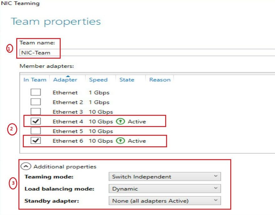
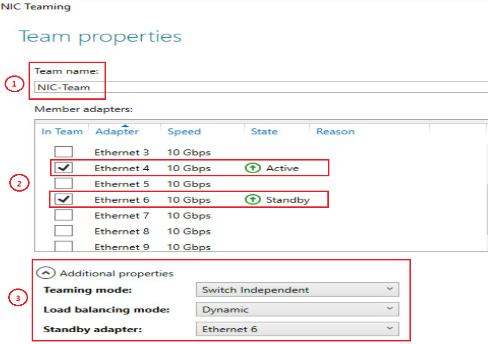
c. As shown in Figure 13, set the team name and select the network adapter that you want to add to the team, set the appropriate properties in Additional properties, and click OK to create the team.
|
|
TIP: · For descriptions of team properties, see Mezzanine Card User Guide. · The creation of a team in the Switch Independent mode is slow. Please wait patiently. |
Figure 13 Setting the new team
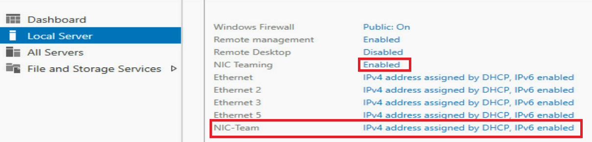
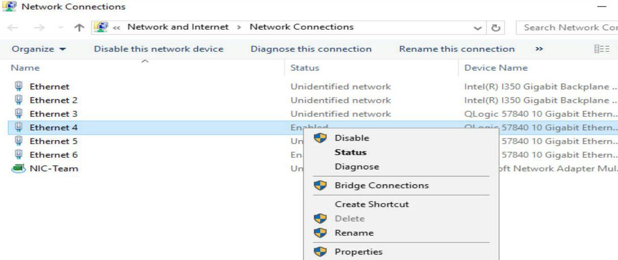
d. As shown in Figure 14, you can see that the state has changed to Enabled. You can also see a new network port named NIC-Team. Click this port to enter the network connection configuration screen.
Figure 14 Viewing the NIC teaming

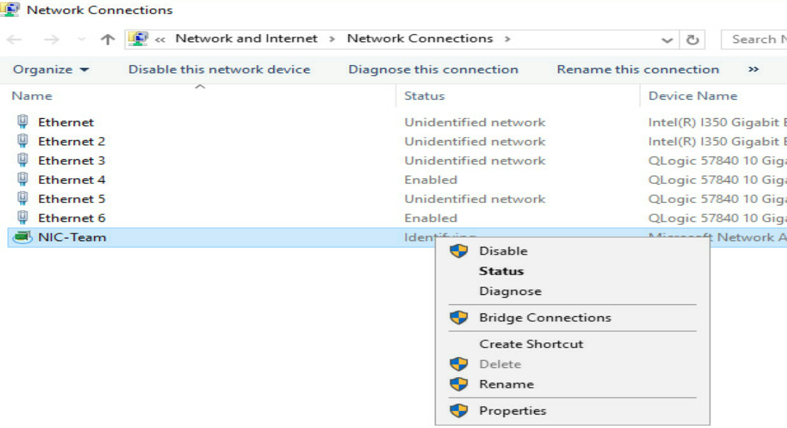
e. As shown in Figure 15, right-click the network port named NIC-Team and select Properties.
Figure 15 Setting the NIC-Team

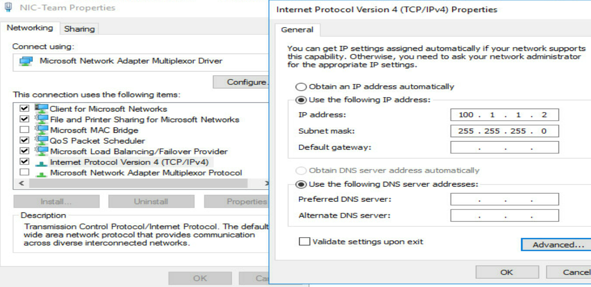
f. As shown in Figure 16, set the IP address of the port named NIC-Team. The IP address of 100.1.1.2/24 is used in this example.
Figure 16 Setting the IP address
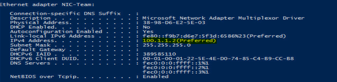
g. As shown in Figure 17, run the cmd command, and execute the ipconfig -all command in the Windows PowerShell screen. You can see that the IP has been configured.
Figure 17 Confirming the IP address of the port

h. VLAN separation exists in this example. You need to configure VLAN ID for all physical ports (Ethernet4 and Ethernet6) joined the team. Here we use the configuration of Ethernet4 as an example to describe the configuration process. In the Network Connections screen, right-click the network port named Ethernet4 and select Properties, as shown in Figure 18.
Figure 18 Setting the physical port in the team

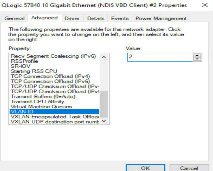
i. As shown in Figure 19, in the pop-up dialog box, select Configure, enter the Advanced tab, select VLAN ID in the Property drop-down menu, and fill in the added VLAN tag in the Value box. In this example, the value of 2 is used.

j. Configure the Ethernet6 port according to the above methods.
Configuring the interconnect module
Interconnecting interconnect modules and mezzanine cards
# Create VLAN 2.
[H3C] vlan2
[H3C-vlan2]quit
# Configure the mode of the Ten-GigabitEthernet 1/0/24 port to trunk and allow VLAN 2 to pass.
[H3C] interface Ten-GigabitEthernet 1/0/24
[H3C-Ten-GigabitEthernet1/0/24] port link-type trunk
[H3C-Ten-GigabitEthernet1/0/24] port trunk permit vlan 2
[H3C-Ten-GigabitEthernet1/0/24] undo port trunk permit vlan 1
[H3C-Ten-GigabitEthernet1/0/24] undo stp enable
[H3C-Ten-GigabitEthernet1/0/24] quit
# Configure the mode of the Ten-GigabitEthernet 2/0/24 port to trunk and allow VLAN 2 to pass.
[H3C] interface Ten-GigabitEthernet 2/0/24
[H3C-Ten-GigabitEthernet2/0/24] port link-type trunk
[H3C-Ten-GigabitEthernet2/0/24] port trunk permit vlan 2
[H3C-Ten-GigabitEthernet2/1/24] undo port trunk permit vlan 1
[H3C-Ten-GigabitEthernet1/0/24] undo stp enable
[H3C-Ten-GigabitEthernet2/0/24] quit
Interconnecting interconnect modules and aggregation switches
# Create a layer-2 aggregation port, add the physical ports to the aggregation group, and allow VLAN 2 to pass.
[H3C] interface Bridge-Aggregation 10
[H3C-Bridge-Aggregation10]
[H3C] interface Ten-GigabitEthernet 1/1/9
[H3C-Ten-GigabitEthernet1/1/9] port link-aggregation group 10
[H3C-Ten-GigabitEthernet1/1/9] quit
[H3C] interface Ten-GigabitEthernet 2/1/9
[H3C-Ten-GigabitEthernet2/1/9] port link-aggregation group 10
[H3C-Ten-GigabitEthernet2/1/9] quit
[H3C] int Bridge-Aggregation 10
[H3C-Bridge-Aggregation10] port link-type trunk
[H3C-Bridge-Aggregation10] port trunk permit vlan 2
[H3C-Bridge-Aggregation10] undo port trunk permit vlan 1
[H3C-Bridge-Aggregation10] quit
# Save the configuration.
[H3C] save
The current configuration will be written to the device. Are you sure? [Y/N]:y
Please input the file name(*.cfg)[flash:/startup.cfg]
(To leave the existing filename unchanged, press the enter key):
Configuring the aggregation switch
# Create VLAN 2.
[H3C] vlan2
[H3C-vlan2]quit
# Create a layer-2 aggregation port, add the physical ports to the aggregation group, and allow VLAN 2 to pass.
[H3C] int Bridge-Aggregation 10
[H3C-Bridge-Aggregation10]
[H3C] interface Ten-GigabitEthernet 1/0/49
[H3C-Ten-GigabitEthernet1/0/49] port link-aggregation group 10
[H3C-Ten-GigabitEthernet1/0/49] quit
[H3C] interface Ten-GigabitEthern 1/0/50
[H3C-Ten-GigabitEthernet1/0/50] port link-aggregation group 10
[H3C-Ten-GigabitEthernet1/0/50] quit
[H3C] int Bridge-Aggregation 10
[H3C-Bridge-Aggregation10] port link-type trunk
[H3C-Bridge-Aggregation10] port trunk permit vlan 2
[H3C-Bridge-Aggregation10] undo port trunk permit vlan 1
[H3C-Bridge-Aggregation10] quit
# You can view the information about the aggregation port and confirm that the aggregation port has been created.
[H3C] display link-aggregation verbose Bridge-Aggregation 10
Loadsharing Type: Shar -- Loadsharing, NonS -- Non-Loadsharing
Port Status: S -- Selected, U -- Unselected, I -- Individual
Port: A -- Auto port, M -- Management port, R -- Reference port
Flags: A -- LACP_Activity, B -- LACP_Timeout, C -- Aggregation,
D -- Synchronization, E -- Collecting, F -- Distributing,
G -- Defaulted, H -- Expired
Aggregate Interface: Bridge-Aggregation10
Aggregation Mode: Static
Loadsharing Type: Shar
Management VLANs: None
Port Status Priority Oper-Key
XGE1/0/49 U 32768 1
XGE1/0/50 S 32768 1
# Create a VLAN port and set the IP address of the port to 100.1.1.1/24.
[H3C] interface vlan 2
[H3C-Vlan-interface2] ip address 100.1.1.1 255.255.255.0
[H3C-Vlan-interface2] quit
# Check the status of VLAN 2 port and confirm that the port is UP.
[H3C-Vlan-interface2]display interface vlan 2 brief
Brief information on interfaces in route mode:
Link: ADM - administratively down; Stby - standby
Protocol: (s) - spoofing
Interface Link Protocol Primary IP Description
Vlan2 UP UP 100.1.1.1
# Save the configuration.
[H3C] save
The current configuration will be written to the device. Are you sure? [Y/N]:y
Please input the file name(*.cfg)[flash:/startup.cfg]
(To leave the existing filename unchanged, press the enter key):
Verifying the configuration
In the OS of the blade server, ping VLAN 2 port on the aggregation switch. Verify that the port can be pinged successfully.
[root@localhost]# ping 100.1.1.2
PING 100.1.1.2(100.1.1.2) 56(84) bytes of data.
64bytes from 100.1.1.2: icmp_seq=1 ttl=255 time=0.808 ms
64bytes from 100.1.1.2: icmp_seq=2 ttl=255 time=0.691 ms
64bytes from 100.1.1.2: icmp_seq=3 ttl=255 time=0.732 ms
64bytes from 100.1.1.2: icmp_seq=4 ttl=255 time=0.679 ms
64bytes from 100.1.1.2: icmp_seq=5 ttl=255 time=0.710 ms
Example: Configuring Ethernet services (pass-through module)
Network requirement
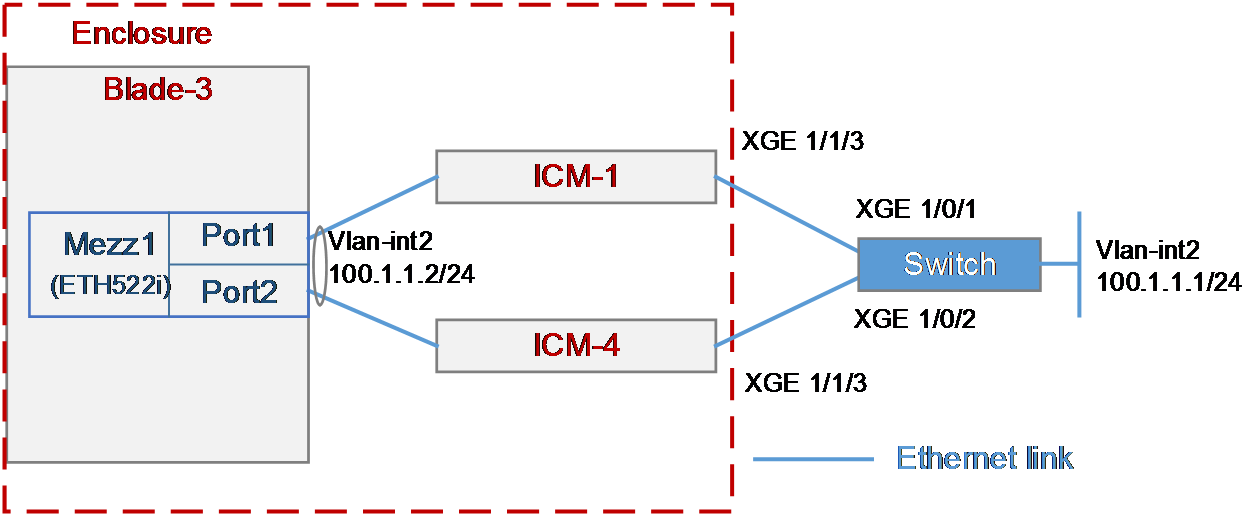
As shown in Figure 20, the blade server and Ethernet pass-through modules are installed in the H3C B16000 blade server chassis. The blade server is installed in slot 3, two Ethernet pass-through modules are installed in slot 1 and slot 4, and the mezzanine card is installed in the mezzanine card slot 1 of the blade server. The XGE 1/1/3 port of each of the two Ethernet pass-through modules is connected to the XGE 1/0/1 or XGE 1/0/2 port of the Ethernet switch.
In this example, the following devices and modules are used: blade server (H3C UniServer B5700 G3), mezzanine card (NIC-ETH522i-Mb-2*10G, "ETH522i"), Ethernet pass-through module (H3C UniServer BT616E), and Ethernet switch (H3C S6800).
In this example, the Red Hat Enterprise Linux 7.5 is installed on the blade server.
The following requirements are expected to be met:
The OS on the blade server can access the external H3C switch, and can still communicate correctly when any pass-through module fails.
Figure 20 Example: Configuring Ethernet service (Ethernet pass-through module)
Analysis
· Before configuration, you need to query the correspondence between the mezzanine card, the external port of the pass-through module, and the mezzanine card port displayed under the OS, to ensure that the correct ports are configured and facilitate the verification after configuration.
· To improve the reliability of internal links of the blade server, you need to configure the bonding function (adopting the active/standby mode) on the mezzanine card ports to bind Port 1 and Port 2 of the mezzanine card to a logic port, so that the blade server can access external networks through the other pass-through module when a pass-through module fails.
· In this example, the bonding function adopts the active/standby mode, indicating that either Port 1 or Port 2 on the mezzanine card receives and sends the traffic, while the other serves as the backup. Therefore, you do not need to aggregate the two links on the switch used to connect the blade server. If the bonding function uses other modes, you need to configure the settings related to the bond mode on the two links.
· In this example, the service traffic between the blade server and the switch is transmitted through the VLAN port. Therefore, you need to configure relevant settings related to VLAN and VLAN ports on the blade server and the switch.
Configuration precautions
Make sure that the blade server's OS can recognize the ETH522i network adapter correctly. If it cannot, install the network adapter driver. For details, see ETH522i Mezzanine Card Module User Guide.
Configuration procedure
Querying port information
Query the correspondence among mezzanine cards, internal ports of interconnect modules, and network adapters under the OS according to "Querying port relations."
In this example, Port 1 and Port 2 of mezzanine card 1 on the blade server in slot 3 are used and are named ens5f0 and ens5f1 under the OS, respectively.
Configuring the mezzanine card
The following information describes the procedure for configuring the bonding function on mezzanine card ports under the OS.
Configure the bonding function of ens5f0 and ens5f1 ports
1. In the OS, execute the nmtui command to start the network adapter configuration tool that comes with the system.
[root@localhost]# nmtui
2. Select Edit a connection to edit the network connection, as shown in Figure 21.
Figure 21 Selecting Edit a connection
3. Select Add to add a new network connection, select the type of connection as Bond, and click Create, as shown in Figure 22.
Figure 22 Adding a "bond" connection

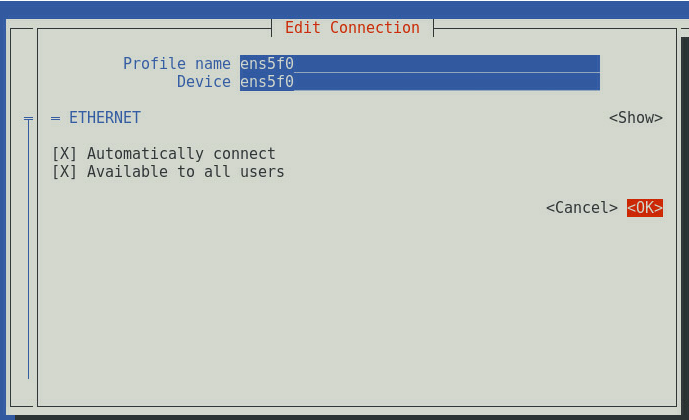
4. As shown in Figure 23, set Profile name and Device, where Profile name is the name of the configuration file and can be set as required. Device must be configured as the device name. In this example, both are configured as Bond1.
Figure 23 Setting the bond connection

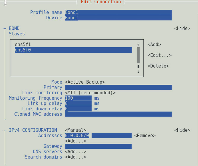
5. Under the BOND Slaves option, select Add and add the ens5f0 slave port, as shown in Figure 24. Then, select OK to save the configuration. Add the ens5f1 slave port in the same way.
6. Set Mode to Active Backup and set the IP address according to the service environment. In this example, the service traffic is transmitted through the VLAN port connected to the bond port. Therefore, you do not need to configure the IP address for the bond port. Set IPv4 CONFIGURATION to Manual, and set the static IP address of the bond port to 0.0.0.0/0, as shown in Figure 25. After the configuration, select OK to save the configuration.
Figure 25 Setting network parameters
7. Press Esc to return to the homepage of the nmtui tool, select Add to add a new network connection, select the type of connection as VLAN, and click Create, as shown in Figure 26.

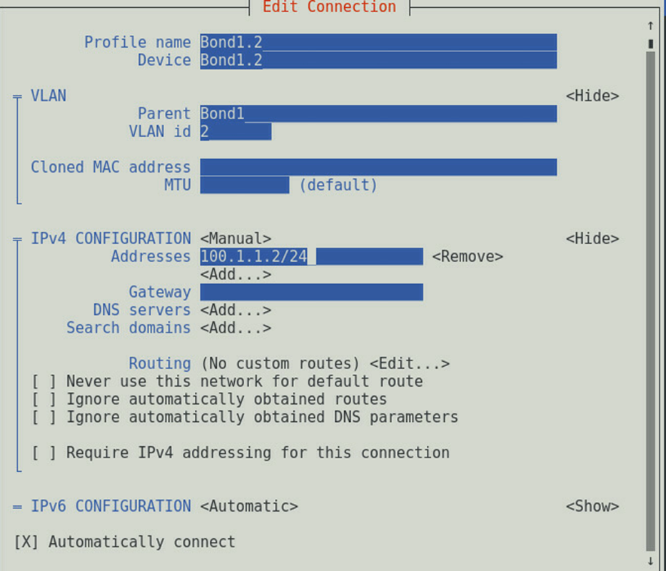
8. As shown in Figure 27, set Profile name, Device and VLAN id, set IPv4 CONFIGURATION to Manual, and set the static IP address of the service network. Then, select OK to save the configuration. This example uses the VLAN ID of 2 and the address100.1.1.2/24.
Figure 27 Setting the IP address of the VLAN slave port connected to the bond port
9. Press Esc to return to the configuration screen.
Restart the network service
Execute the systemctl restart network command to restart the network service.
[root@localhost]# systemctl restart network
Viewing the network adapter configuration
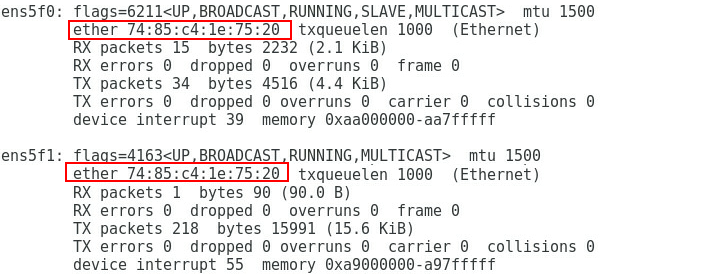
Execute the ifconfig command to view the Bond1 and Bond1.2 configurations, as shown in Figure 28. Note that the physical addresses of the aggregation port and the two physical network adapters are the same in the active/standby mode, as shown in Figure 29.
Figure 28 Viewing the network adapter configuration (I)
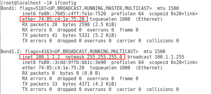
Figure 29 Viewing the network adapter configuration (II)
Configuring switch
Creating a VLAN
Create VLAN 2, and ensure that the switch port and the mezzanine card port of the peer blade server reside in the same VLAN.
[H3C] vlan2
[H3C-vlan2]quit
Configuring the port to trunk
To enable the blade server to send VLAN 2 packets to the switch, configure the link types of Ten-GigabitEthernet 1/0/1 and Ten-GigabitEthernet 1/0/2 ports to trunk and permit VLAN 2 packets to pass.
[H3C] interface Ten-GigabitEthernet 1/0/1
[H3C-Ten-GigabitEthernet1/0/1] port link-type trunk
[H3C-Ten-GigabitEthernet1/0/1] port trunk permit vlan 2
[H3C-Ten-GigabitEthernet1/0/1] quit
[H3C] interface Ten-GigabitEthernet 1/0/2
[H3C-Ten-GigabitEthernet1/0/2] port link-type trunk
[H3C-Ten-GigabitEthernet1/0/2] port trunk permit vlan 2
[H3C-Ten-GigabitEthernet1/0/2] quit
Configuring the VLAN port
Create VLAN 2 port and set its IP address to 100.1.1.1/24. This port is used to access the peer blade server.
[H3C] interface vlan 2
[H3C-Vlan-interface2] ip address 100.1.1.1 255.255.255.0
[H3C-Vlan-interface2] quit
Saving the configuration
Execute the save command to save the configuration, and modify the configuration file name as required. For example, if you press Enter directly, the name is not modified.
[H3C]save
The current configuration will be written to the device. Are you sure? [Y/N]:y
Please input the file name(*.cfg)[flash:/startup.cfg]
(To leave the existing filename unchanged, press the enter key):
Note: After the configuration, execute the display current-configuration command to view the final configuration.
Verifying the configuration
Ping the IP address of VLAN 2 port on the blade server on the switch. Verify that the address can be pinged successfully.
[H3C] ping 100.1.1.2
PING 100.1.1.2(100.1.1.2) 56(84) bytes of data.
64bytes from 100.1.1.2: icmp_seq=1 ttl=255 time=0.808 ms
64bytes from 100.1.1.2: icmp_seq=2 ttl=255 time=0.691 ms
64bytes from 100.1.1.2: icmp_seq=3 ttl=255 time=0.732 ms
64bytes from 100.1.1.2: icmp_seq=4 ttl=255 time=0.679 ms
64bytes from 100.1.1.2: icmp_seq=5 ttl=255 time=0.710 ms
Example: Configuring Ethernet services (monitor link)
Network requirement
As shown in Figure 30, the blade server and interconnect modules are installed in the H3C B16000 blade server chassis. The blade server is installed in slot 12, two interconnect modules are installed in slot 1 and slot 4, and the mezzanine card is installed in the mezzanine card slot 1 of the blade server. The XGE 1/1/9 port of each of the two interconnect modules is connected to the XGE 1/0/49 and XGE 1/0/50 ports of the Ethernet switch.
In this example, the following devices and modules are used: mezzanine card (NIC-ETH561i-Mb-4*10G, "ETH561i"), interconnect module (BX720E), and Ethernet switch (H3C switch).
It is required that the OS on the blade server can access the external Ethernet network through the switch (in this example, accessing VLAN 2 port on the switch is used as an example). In addition, the following is required to be implemented through the Monitor Link technology: When the uplink device of any interconnect module fails, the uplink port (XGE 1/1/9) is down, and the downlink port (XGE 1/0/24) of the same interconnect module is down as well, so that the system can sense the uplink status changes and implement link switching.
Figure 30 Example: Configuring Ethernet services
Analysis
· To improve the reliability of internal links in the blade server chassis, you need to configure the bonding function under the OS to bind Port 3 and Port 4 of the mezzanine card to a logic port. In this example, the bonding function adopts the active/standby mode.
· In this example, the bonding function adopts the active/standby mode, indicating that either Port 3 or Port 4 on the mezzanine card receives and sends the traffic, while the other serves as the backup. Therefore, you do not need to aggregate the links over the XGE 1/0/24 internal ports of the two interconnect module. If the bonding function uses other modes, you need to aggregate the links over the internal ports of the two interconnect modules.
· As a best practice, disable the STP function of the internal ports on the interconnect modules, to prevent the rebooting or plugging in/out of the blade server from causing the STP of the interconnect modules to start calculating and resulting in short disconnection of external ports on the interconnect modules.
· When the uplink port of the interconnect module is down, the downlink port need to be down as well. To achieve this, you need to create a monitor link group and specify its uplink and downlink ports.
Software versions used
This example was created and verified on SWITCH_SYS-1.02.03 and OM-1.02.03 versions.
Configuration precautions
· Make sure that the OS can recognize the ETH561i network adapter correctly. If it cannot, install the network adapter driver according to the ETH561i Mezzanine Card Module User Guide.
· One interface can only belong to one monitor link group.
· It is recommended to configure the uplink port of the monitor link first to avoid unnecessary down/up status changes on the downlink port.
· It is not allowed to add an aggregation interface and its corresponding member ports to the same monitor link group.
· The delayed switchback mechanism can avoid frequent downlink switchover caused by uplink flapping of the monitor link group. When the uplink port of the monitor link group returns to the UP state and maintains it for a period of time, the downlink port restores to the UP state.
Configuration procedure
Querying port information
Query the correspondence among mezzanine cards, internal ports of the interconnect modules, and network adapters under the OS according to "Querying port relations."
It can be learned that:
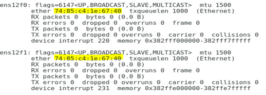
· In this example, Port 3 and Port 4 of mezzanine card 1 are used and are named ens12f0 and ens12f1 under the OS, respectively.
· Ten-gigabitethernet 1/0/24 ports of interconnect modules 1 and 4 are used in this example.
Configuring the mezzanine card
The following information describes the procedure for configuring Linux and Windows operating systems on the blade server.
Procedure for configuring Linux
|
|
NOTE: The following information provides the procedure for configuring the bonding function under Red Hat 7.5. |
1. Configure the bonding function of ens12f0 and ens12f1 ports
a. Execute the nmtui command to start the network adapter configuration tool that comes with the system.
[root@localhost]# nmtui
b. Select Edit a connection to edit the network connection, as shown in Figure 31.
Figure 31 Selecting Edit a connection

c. Select Add to add a new network connection, select the type of connection as Bond, and click Create, as shown in Figure 32.
Figure 32 Adding a "bond" connection

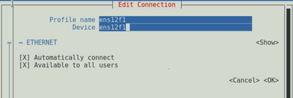
d. As shown in Figure 33, set Profile name and Device.
Figure 33 Setting the bond connection

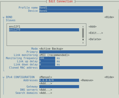
e. Under the BOND Slaves option, select Add and add ens12f0 and ens12f1 slave ports, as shown in Figure 34.
f. Set Mode to Active Backup and set the IP address according to the service environment. In this example, the service traffic is transmitted through the VLAN port connected to the bond port. Therefore, set the static IP address of the bond master port to 0.0.0.0/0, as shown in Figure 35.
Figure 35 Setting network parameters
g. Return to the homepage of the nmtui tool, select Add to add a new network connection, select the type of connection as VLAN, and click Create, as shown in Figure 36.

h. As shown in Figure 37, set Profile name, Device and VLAN id, and configure the IP address of the service network. This example uses the VLAN ID of 2 and the static IP address 100.1.1.2/24.
Figure 37 Setting the IP address of the VLAN slave port connected to the bond port

i. Then, press Esc to return to the configuration screen.
2. Execute the systemctl restart network command to restart the network service.
[root@localhost]# systemctl restart network
3. Execute the ifconfig command to view the Bond1 and Bond1.2 configurations as shown in Figure 38 and Figure 39. Note that the physical addresses of the aggregation port and the two physical network adapters are the same in the active/standby mode.
Figure 38 Viewing the network adapter configuration (I)
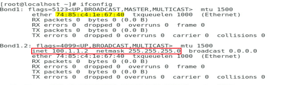
Figure 39 Viewing the network adapter configuration (II)
Procedure for configuring Windows
|
|
NOTE: The following information provides the procedure for configuring NIC teaming function on the Windows Server. The Windows Server 2016 is used as an example. |
1. Check the correspondence of network adapter ports.
Query the correspondence among mezzanine cards, internal ports of interconnect modules, and network adapters of the OS according to "Querying port relations." In this example, Port 3 and Port 4 of mezzanine card 1 are used and are named Ethernet4 and Ethernet6 under the OS, respectively.
2. Configure the teaming.
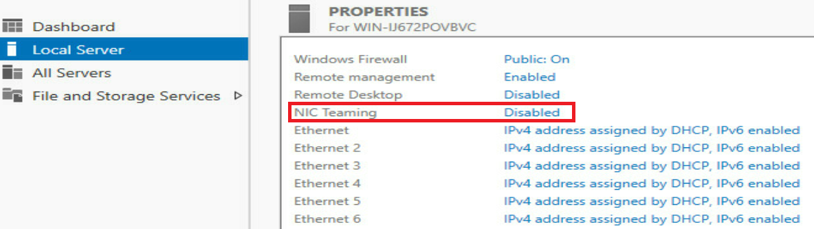
a. As shown in Figure 40, click Disabled in Server Manager > Local Server > NIC Teaming to open the configuration screen of NIC Teaming.
Figure 40 Opening the configuration screen of NIC Teaming
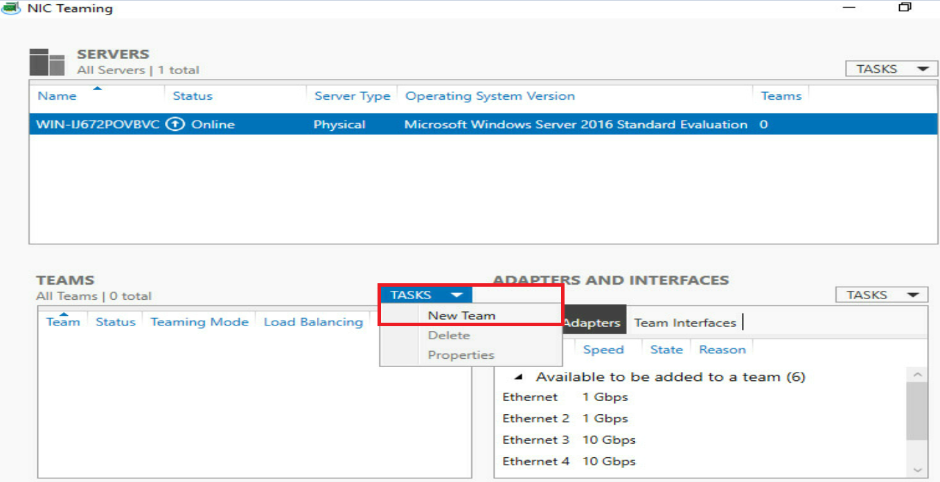
b. As shown in Figure 41, click TASKS > NEW Team to create a team.
c. As shown in Figure 42, set the team name and select the network adapter that you want to add to the team, set the appropriate properties in Additional properties, and click OK to create the team.
|
|
TIP: · For descriptions of team properties, see Mezzanine Card User Guide. · The creation of a team in the Switch Independent mode is slow. Please wait patiently. |
Figure 42 Setting the new team
d. As shown in Figure 43, you can see that the state has changed to Enabled. You can also see a new network port named NIC-Team. Click this port to enter the network connection configuration screen.
Figure 43 Viewing the NIC teaming
e. As shown in Figure 44, right-click the network port named NIC-Team and select Properties.
Figure 44 Setting the NIC-Team
f. As shown in Figure 45, set the IP address of the port named NIC-Team. The IP address of 100.1.1.2/24 is used in this example.
Figure 45 Setting the IP address

g. As shown in Figure 46, run the cmd command, and execute the ipconfig -all command in the Windows PowerShell screen. You can see that the IP has been configured.
Figure 46 Confirming the IP address of the port
h. VLAN separation exists in this example. You need to configure VLAN ID for all physical ports (Ethernet4 and Ethernet6) joined the team. Here we use the configuration of Ethernet4 as an example to describe the configuration process. In the Network Connections screen, right-click the network port named Ethernet4 and select Properties, as shown in Figure 47.
Figure 47 Setting the physical port in the team
i. As shown in Figure 48, in the pop-up dialog box, select Configure, enter the Advanced tab, select VLAN ID in the Property drop-down menu, and fill in the added VLAN tag in the Value box. In this example, the value of 2 is used.
j. Configure the Ethernet6 port according to the above methods.
Configuring the interconnect module
|
|
NOTE: In this example, the interconnect modules 1 and 4 need to be configured as follows. |
Configuring the monitor link
# Enable monitor link protocol (which is enabled by default) globally.
<H3C> system-view
[H3C] undo monitor-link disable
# Create the monitor link group and add the ports to the monitor link group (configure the Ten-GigabitEthernet 1/1/9 external port of the interconnect module as the uplink port and the Ten-GigabitEthernet 1/0/24 internal port as the downlink port).
[H3C] monitor-link group 1
[H3C-mtlk-group1] port Ten-GigabitEthernet 1/1/9 uplink
[H3C-mtlk-group1] port Ten-GigabitEthernet 1/0/24 downlink
# View the configuration of the monitor link group.
[H3C]display monitor-link group 1
Monitor link group 1 information:
Group status : UP
Downlink up-delay: 10(s)
Last-up-time : 10:43:05 2019/12/19
Last-down-time : -
Up-port-threshold: 1
Member Role Status
--------------------------------------------------------
XGE1/1/9 UPLINK UP
XGE1/0/24 DOWNLINK UP
Interconnecting interconnect modules and mezzanine cards
# Create VLAN 2.
[H3C] vlan2
[H3C-vlan2]quit
# Configure the mode of the Ten-GigabitEthernet 1/0/24 port to trunk and allow VLAN 2 to pass.
[H3C] interface Ten-GigabitEthernet 1/0/24
[H3C-Ten-GigabitEthernet1/0/24] port link-type trunk
[H3C-Ten-GigabitEthernet1/0/24] port trunk permit vlan 2
[H3C-Ten-GigabitEthernet1/0/24] undo port trunk permit vlan 1
[H3C-Ten-GigabitEthernet1/0/24] undo stp enable
[H3C-Ten-GigabitEthernet1/0/24] quit
Interconnecting interconnect modules and aggregation switches
# Configure the Ten-GigabitEthernet 1/1/9 port to a trunk port and permit VLAN 2 packets to pass.
[H3C] interface Ten-GigabitEthernet 1/1/9
[H3C-Ten-GigabitEthernet1/1/9] port link-type trunk
[H3C-Ten-GigabitEthernet1/1/9] port trunk permit vlan 2
[H3C-Ten-GigabitEthernet1/1/9] undo port trunk permit vlan 1
[H3C-Ten-GigabitEthernet1/1/9] quit
# Save the configuration.
[H3C] save
The current configuration will be written to the device. Are you sure? [Y/N]:y
Please input the file name(*.cfg)[flash:/startup.cfg]
(To leave the existing filename unchanged, press the enter key):
Configuring the aggregation switch
# Create VLAN 2.
[H3C] vlan2
[H3C-vlan2]quit
# Configure the Ten-GigabitEthernet 1/0/49 and Ten-GigabitEthernet 1/0/50 ports to trunk ports and permit VLAN 2 packets to pass.
[H3C] interface Ten-GigabitEthernet 1/0/49
[H3C-Ten-GigabitEthernet1/0/49] port link-type trunk
[H3C-Ten-GigabitEthernet1/0/49] port trunk permit vlan 2
[H3C-Ten-GigabitEthernet1/0/49] undo port trunk permit vlan 1
[H3C-Ten-GigabitEthernet1/0/49] quit
[H3C] interface Ten-GigabitEthernet 1/0/50
[H3C-Ten-GigabitEthernet1/0/50] port link-type trunk
[H3C-Ten-GigabitEthernet1/0/49] port trunk permit vlan 2
[H3C-Ten-GigabitEthernet1/0/49] undo port trunk permit vlan 1
[H3C-Ten-GigabitEthernet1/0/50] quit
# Create a VLAN port and set the IP address of the port to 100.1.1.1/24.
[H3C] interface vlan 2
[H3C-Vlan-interface2] ip address 100.1.1.1 255.255.255.0
[H3C-Vlan-interface2] quit
# Check the status of VLAN 2 port and confirm that the port is UP.
[H3C-Vlan-interface2]display interface vlan 2 brief
Brief information on interfaces in route mode:
Link: ADM - administratively down; Stby - standby
Protocol: (s) - spoofing
Interface Link Protocol Primary IP Description
Vlan2 UP UP 100.1.1.1
# Save the configuration.
[H3C] save
The current configuration will be written to the device. Are you sure? [Y/N]:y
Please input the file name(*.cfg)[flash:/startup.cfg]
(To leave the existing filename unchanged, press the enter key):
Verifying the configuration
Verifying the configuration under the Linux system
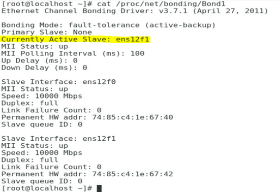
1. As shown in Figure 49, execute the cat/proc/net/bonding/Bond1 command on the Linux system to view the current bond information and the currently active slave port displayed is ens12f1.
Figure 49 Viewing the bond information
2. Ping the VLAN 2 port on the aggregation switch. Verify that the port can be pinged successfully.
[root@localhost]# ping 100.1.1.1
PING 100.1.1.1(100.1.1.1) 56(84) bytes of data.
64bytes from 100.1.1.1: icmp_seq=1 ttl=255 time=0.606 ms
64bytes from 100.1.1.1: icmp_seq=2 ttl=255 time=0.658 ms
64bytes from 100.1.1.1: icmp_seq=3 ttl=255 time=0.567 ms
64bytes from 100.1.1.1: icmp_seq=4 ttl=255 time=0.942 ms
64bytes from 100.1.1.1: icmp_seq=5 ttl=255 time=0.743 ms
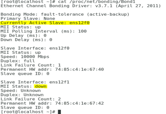
3. As shown in Figure 50, shut down the XGE 1/0/49 port of the aggregation switch to simulate the case where the uplink of interconnect module 1 corresponding to the ens12f1 is down. View the bond information in Linux again, and the currently active slave port displayed is ens12f0.
Figure 50 Viewing the bond information
4. Ping the VLAN 2 port on the aggregation switch in Linux. Verify that the port can be pinged successfully, indicating that the link has been switched without affecting service communication.
[root@localhost]# ping 100.1.1.1
PING 100.1.1.1(100.1.1.1) 56(84) bytes of data.
64bytes from 100.1.1.1: icmp_seq=1 ttl=255 time=1.606 ms
64bytes from 100.1.1.1: icmp_seq=2 ttl=255 time=0.896 ms
64bytes from 100.1.1.1: icmp_seq=3 ttl=255 time=0.542 ms
64bytes from 100.1.1.1: icmp_seq=4 ttl=255 time=0.672 ms
64bytes from 100.1.1.1: icmp_seq=5 ttl=255 time=0.920 ms
Verifying the configuration under the Windows system
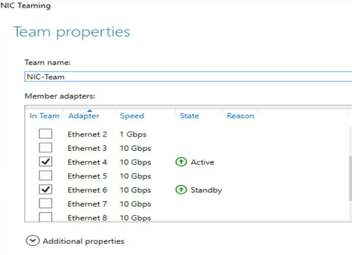
1. As shown in Figure 51, click Disabled in Server Manager > Local Server > NIC Teaming in the OS to open the configuration screen of NIC Teaming. Select NIC-Team in Team name to view the current team information. The active port is Ethernet 4.
Figure 51 Viewing the team information
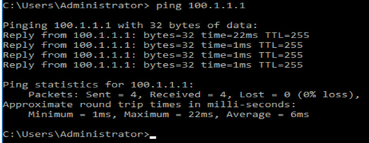
2. As shown in Figure 52, ping the VLAN 2 port on the aggregation switch in Windows. Verify that the port can be pinged successfully.
Figure 52 Verifying link connectivity
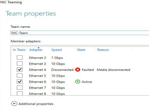
3. As shown in Figure 53, shut down the XGE 1/0/49 port of the aggregation switch to simulate the case where the uplink of interconnect module 1 corresponding to the Ethernet 4 is down. View the team information in Windows again, and the active port displayed is Ethernet 6.
Figure 53 Viewing the team information
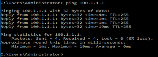
4. As shown in Figure 54, ping the VLAN 2 port on the aggregation switch in Windows again. Verify that the port can be pinged successfully. indicating that the link has been switched without affecting service communication.
Figure 54 Verifying link connectivity
Common operations
Querying port relations
Query the interface connection between mezzanine cards and interconnection modules
Please use the H3C networking query tool on the official website to view the port connection relation between mezzanine cards and interconnect modules.
Query the MAC address or WWN number of the mezzanine card.
Log in to the OM Web page and click Blade Server Management/Target Blade Server/Port Mapping to view the port MAC address of the Ethernet Mezzanine card and the port WWN number of the FC mezzanine card.
Querying the port correspondence between the network adapter and the mezzanine card under the OS
1. To view the MAC addresses of all network adapters, execute the ipconfig -all command in Windows and execute the ifconfig command in Linux.
2. According to the MAC addresses or WWNs queried above, you can learn the correspondence between the ports on the network adapter and the mezzanine card under the OS.
