- Table of Contents
-
- H3C UniServer B16000 Blade Server Configuration Examples-6W100
- 01-FC and FCoE Services Configuration Examples
- 02-Ethernet Services Configuration Examples
- 03-Virtual Management Network Configuration Examples
- 04-Shared Storage Configuration Examples
- 05-VC Configuration Examples
- 06-Chassis Profile Configuration Examples
- 07-IB Service Configuration Examples
- 08-Blade Server FIST Configuration Examples
- Related Documents
-
| Title | Size | Download |
|---|---|---|
| 06-Chassis Profile Configuration Examples | 1.46 MB |
Example: Configuring chassis profiles
Pre-configuring the interconnection module
Creating the network profile Profile-1
Applying the blade server profile
Configuring each service IP address
Introduction
The following information provides examples for configuring the OM chassis profiles.
Hardware compatibility
Table 1 lists the hardware to be used in typical networking modes. If there are multiple models in a cell, the hardware of these models is appropriate for this configuration.
Table 1 Hardware compatibility
|
Configuration example |
Hardware compatibility |
|||
|
NIC |
Interconnection module |
External switch |
Backend storage |
|
|
Chassis profile configuration example |
· ETH521i · ETH522i |
· BX720EF · BX720E · BX1020EF |
Ethernet switch |
NA |
Prerequisites
The configuration examples were created and verified in a lab environment, and all the devices were started with the factory default configuration. When you are working on a live network, make sure you understand the potential impact of every command on your network.
The following information assumes that you have understood the features, such as IRF, port aggregation and port isolation, and known how to use H3C blade servers, interconnection modules (ICMs), and operating systems (OSs).
The following configuration examples mainly describe the configuration process on the blade chassis side. As a best practice, modify the configurations of the external network based on the actual requirements.
Example: Configuring chassis profiles
Network requirements
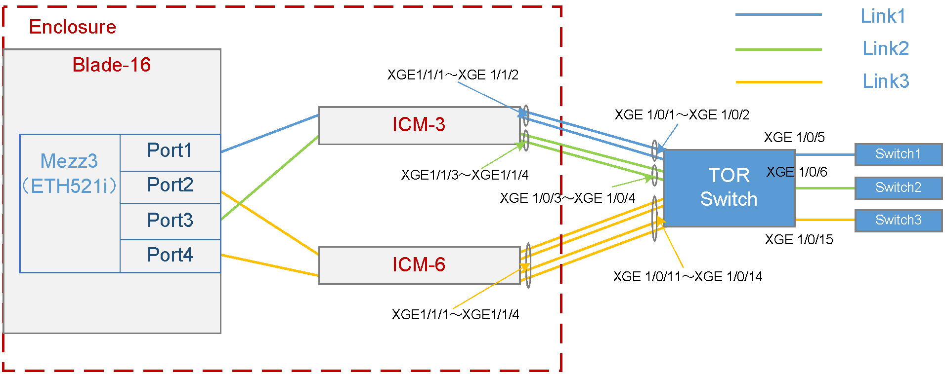
As shown in Figure 1, a blade server and an ICM are installed in the H3C UniServer B16000 blade server chassis. In this example, the blade server used is H3C UniServer B5700 G3, the Mezz NIC used is NIC-ETH521i-Mb-4*10G (ETH521i for short), the RAID card used is RAID-P5408-Mf-8i, and the ICM used is H3C UniServer BX720E. The TOR switch used is H3C S5820V2-52QF.
· The blade server is installed in slot 16. The Mezz NIC is installed in the slot of Mezz 3 at the rear of the blade server. The RAID card is installed in the front Mezz slot.
· Two ICMs are installed in the slots of ICM 3 and ICM 6 respectively, and connect to the TOR switch through external ports. The external ports of ICM 3, including XGE1/1/1 (Port 1), XGE1/1/2 (Port 2), XGE1/1/3 (Port 3), and XGE1/1/4 (Port 4), are connected to the ports XGE1/0/1, XGE1/0/2, XGE1/0/3, and XGE1/0/4 of the TOR switch in turn. The external ports of ICM 6, including XGE1/1/1 (Port 1), XGE1/1/2 (Port 2), XGE1/1/3 (Port 3), and XGE1/1/4 (Port 4), are connected to the ports XGE1/0/11, XGE1/0/12, XGE1/0/13, and XGE1/0/14 of the TOR switch in turn.
· On the TOR switch, ports XGE1/0/1 and XGE1/0/2 are added to the aggregation group and allow traffic of VLAN 100 to pass through; ports XGE1/0/3 and XGE1/0/4 are added to the aggregation group and allow traffic of VLAN 10 to pass through; ports XGE1/0/11, XGE1/0/12, XGE1/0/13, and XGE1/0/14 are added to the aggregation group and allow traffic of VLAN 400 and VLAN 500 to pass through. Port XGE1/0/5 allows VLAN 100 to connect to Switch 1 (acting as the access switch of the R&D Department), port XGE1/0/6 allows VLAN 10 to connect to Switch 2 (acting as the access switch of the Quality Department), and port XGE1/0/15 allows VLAN 400 and VLAN 500 to connect to Switch 3 (acting as the access switch of the Marketing Department).
A chassis profile needs to be configured so that different departments of the company can access different services on the blade server. The specific requirements are as follows:
· To ensure stability of services, back up the BIOS and RAID configurations of the blade server before service deployment, and meanwhile ensure redundancy of service data.
· Allocate the R&D Department to VLAN 100 and the gateway address is 192.168.20.2/24. This department needs to access the service resources of the blade server in VLAN 200 through Link 1 and the service IP address is 192.168.20.1/24.
· Allocate the Marketing Department to VLAN 400 and VLAN 500 and the gateway addresses are 192.168.40.2/24 and 192.168.50.2/24. This department needs to access the service resources of the blade server in VLAN 400 and VLAN 500 through Link 3 and the service IP addresses are 192.168.40.1/24 and 192.168.50.1/24.
· Allocate the Quality Department to VLAN 10, and the gateway address is 192.168.1.2/24. This department needs to access the service resources of the blade server in VLAN 10 through Link 2, and the service IP address is 192.168.1.1/24.
· To ensure reliability of external links, configure link aggregation on the uplink port (external port of the ICM) and TOR switch ports.
· After the blade server is replaced by the same type of blade server, no configuration is needed, and the original network configuration is still effective.
· The detailed port connections for the chassis profile networking are shown in Table 2.
Table 2 Port connections for the chassis profile networking
|
Port No. of Mezz NIC |
ICM connected through the ICM internal port |
ICM internal port No. |
Connected TOR switch port |
Networking link |
Application scenarios |
|
Port1 |
ICM-3 |
XGE1/1/1 (Port 1) |
XGE1/0/1 |
Link1 · Traffic of VLAN 200 can pass through within the chassis. · Traffic of VLAN 100 can pass through outside the chassis. · VLAN mapping is deployed on the chassis egress to map VLAN 200 to VLAN 100. |
Applicable to service scenarios requiring VLAN mapping |
|
XGE1/1/2 (Port 2) |
XGE1/0/2 |
||||
|
Port3 |
ICM-3 |
XGE1/1/3 (Port 3) |
XGE1/0/3 |
Link2 · Traffic of VLAN 10 can pass through within the chassis. · Traffic of VLAN 10 can pass through outside the chassis. |
Applicable to service scenarios requiring a single VLAN |
|
XGE1/1/4 (Port 4) |
XGE1/0/4 |
||||
|
Port2 |
ICM-6 |
XGE1/1/1 (Port 1) |
XGE1/0/11 |
Link3 · Traffic of VLAN 400 and VLAN 500 can pass through within the chassis. · Traffic of VLAN 400 and VLAN 500 can pass through outside the chassis. |
Applicable to service scenarios requiring multiple VLANs |
|
XGE1/1/2 (Port 2) |
XGE1/0/12 |
||||
|
Port4 |
ICM-6 |
XGE1/1/3 (Port 3) |
XGE1/0/13 |
||
|
XGE1/1/4 (Port 4) |
XGE1/01/4 |
Analysis
· To back up the BIOS configuration and RAID configuration of the blade server, create the BIOS and RAID profiles and apply them to the blade server.
· To ensure the redundancy of service data, set the RAID level to RAID 1.
· To ensure that the R&D Department in VLAN 100 can access the service resources of the blade server in VLAN 200, Port 1 of the Mezz NIC in Blade 16 must be able to communicate with the TOR switch ports (XGE1/0/1 and XGE1/0/2) through the external port (uplink port) of ICM 3. In addition, Port 1 of Mezz NIC allows the traffic of VLAN 200 to pass through, and the TOR switch ports (XGE1/0/1 and XGE1/0/2) allow the traffic of VLAN 100 to pass through. You also need to deploy VLAN mapping in the OM to map VLAN 200 to VLAN 100.
· To ensure that the Quality Department in VLAN 10 can access the public service resources of the blade server in VLAN 10, Port 3 of the Mezz NIC in Blade 16 must be able to communicate with the TOR switch ports (XGE1/0/3 and XGE1/0/4) through the external port (uplink port) of ICM 3. In addition, Port 1 of Mezz NIC and TOR switch ports allow the traffic of VLAN 10 to pass through.
· To ensure that the Marketing Department in VLAN 400 and VLAN 500 can access the service resources of the blade server in VLAN 400 and VLAN 500, Port 2 and Port 4 of the Mezz NIC in Blade 16 must be able to communicate with the TOR switch ports (XGE1/0/11, XGE1/0/12, XGE1/0/13, and XGE1/0/14) through the external port (uplink port) of ICM 6. In addition, Port 2 and Port 4 of Mezz NIC and TOR switch ports (XGE1/0/11, XGE1/0/12, XGE1/0/13, and XGE1/0/14) allow the traffic of both VLAN 400 and VLAN 500 to pass through.
· To ensure the above service network, create a series of network profiles (vNETn), and define the VLANs allowed to pass through the network and the bound uplink ports (that is, the external ports of the ICM). For the vNET bound with VLAN ID, create different uplink shared ports (SUS-1 and SUS-2) and define the allowed VLANs. The mapping between the service network and vNET, and that between the vNET and SUS are as follows:
¡ To ensure the service requirements of the R&D Department, create vNET 1 to allow the traffic of VLAN 100 to pass through (by creating SUS-1), and bind ports TenGE1/1/1 and TenGE1/1/2 of ICM 3 as the uplink port.
¡ To ensure the service requirements of the Quality Department, create vNET 2 that works in Tunneling mode, and bind ports XGE1/1/3 and XGE1/1/4 of ICM 3 as the uplink port.
¡ To ensure the service requirements of the Marketing Department, create vNET 3 and vNET 4 to allow the traffic of VLAN 400 and VLAN 500 to pass through (by creating SUS-2), and bind ports XGE1/1/1 to XGE1/1/4 of ICM 6 as the uplink port.
· To ensure the link connection between the Mezz NIC and TOR switch ports, create a network profile Profile-1 to bind different vNETs and different Mezz NIC ports in turn.
· To ensure that the BIOS profile, RAID profile, and network profile configurations take effect on the blade server, associate the created BIOS profile, RAID profile, network profile to form the blade server profile Bladeprofile-1 and apply it to the blade server.
· To improve reliability of external links, configure link aggregation on the uplink port (external port of the ICM) and TOR switch ports.
· To ensure that each department's VLAN has a gateway address, configure an IP address for each VLAN on the TOR switch as the gateway address.
· After the blade server is replaced, you only need to ensure that the system-side configuration (that is, the system configuration and service software configuration) of the blade server remains unchanged, and the original communication network can still be used normally.
· To ensure that the system-side configuration of the blade server remains unchanged, configure the BIOS profile and RAID profile so that the blade server uses the same BIOS and RAID configuration before and after replacement of the blade server.
Software versions used
In this example, data is configured and verified on the ICM (UN_BLADE-OM-1.02.03) and OM (UN_BLADE-SWITCH_SYS-1.02.03).
Procedures
Logging in to the OM
1. Open the browser on the PC, enter the IP address of the OM Web page (format: https://OM_ip_address). Enter the username and password of the administrator. Click Login.
Creating BIOS profiles
1. Select Profile Template Management > Blade Server Profile Template, and click Create.
2. Perform the following operations in the dialog box displayed:
a. Set the blade server profile template name to BladeProfile-1.
b. Select the blade server model B5700.
c. Click + in the row of BIOS Profile Configuration. In the BIOS profile configuration list displayed, retain default values of all parameters.
Creating RAID profiles
1. Click + in the BIOS profile configuration area. The BIOS profile configuration list opens.
2. Perform the following operations sequentially:
a. Enable the RAID configuration.
b. Select the RAID card model RAID-P5408-Mf-8i.
3. Click Add in the row of Logical Drive, and select the RAID level RAID1 in the dialog box displayed.
4. Click + in the logical drive list, and add two physical disks, and click OK.
5. Click Save to complete configuration of the BIOS profile and RAID profile.
Creating vNET-1
1. Select Enclosure Profile Management > Profile Template Management > Network Profile Template > Shared Uplink Port Template > Create.
2. Configure the following parameters according to the configuration analysis:
a. Set Shared Uplink Port Name to SUS-1.
b. Set Connection Mode to Dynamic Aggregation. In the Add Port area, select the ICM in slot 3, and select two external ports, Port 1 (XGE1/1/1) and Port 2 (XGE1/1/2), as the uplink ports of the vNET-1 network profile.
c. In the Add Associated Network list, click Create.
3. Configure the following parameters in the Add Network Profile Template dialog box:
a. Set Network Addition Mode to Single.
b. Set Network Name to vNET-1.
c. Set VLAN ID to 100.
d. Click OK.
4. Click Apply.
Creating vNET-2
1. Select Enclosure Profile Management > Profile Template Management > Net Template > Create.
2. Configure the following parameters according to the configuration analysis:
a. Set Network Name to vNET-2.
b. Enable the VLAN Tunneling function.
c. Set Connection Mode to Dynamic Aggregation. In the Add Port area, select the ICM in slot 3, and select two external ports, Port 3 (XGE1/1/1) and Port 4 (XGE1/1/2), as the uplink ports of the vNET-2 network profile.
d. Click Apply.
Creating vNET-3 and vNET-4
1. Select Enclosure Profile Management > Profile Template Management > Network Profile Template > Shared Uplink Port Template > Create.
2. Configure the following parameters according to the configuration analysis:
a. Set Shared Uplink Port Name to SUS-2.
b. Set Connection Mode to Dynamic Aggregation. In the row of Add Port, select the ICM in slot 6, and then select its four external ports: Port 1 (XGE1/1/1), Port 2 (XGE1/2), Port 3 (XGE1/1/3), and Port 4 (XGE1/1/4) as the uplink ports oft the vNET-3 and vNET-4 network profiles.
c. In the Add Associated Network list, click Create.
3. Configure the following parameters in the Add Associated Network dialog box:
a. Set Network Addition Mode to Single.
b. Set Network Name to vNET-3.
c. Set VLAN ID to 400.
d. Click OK.
4. Configure the following parameters in the Add Associated Network dialog box:
a. Set Network Addition Mode to Single.
b. Set Network Name to vNET-4.
c. Set VLAN ID to 500.
d. Click OK.
5. Click OK.
Pre-configuring the interconnection module
|
|
IMPORTANT: To ensure the normal application of the blade server profile, you need to pre-configure the ICM before configuration and application. |
1. Select Enclosure Profile Management > Profile Template Management > Network Profile Template > Click here. The ICM pre-configuration dialog box opens.
2. Select ICM-3 and ICM-6 that need to be pre-configured, enable Netconf Service, and click OK to complete the pre-configuration of the ICMs.
Creating the network profile Profile-1
1. Select Enclosure Profile Management > Profile Template Management > Network Profile Template > Profile Template > Create.
2. Configure the following parameters of the blade server profile according to the configuration analysis:
a. Set Name to Profile-1.
b. Set Blade Serer Model to B5700.
c. Set Slot No. to 3.
d. Set Type to NIC-ETH521i-Mb-4*10G.
e. Configure the networks bound to Port 1 to Port 4.
3. Configure Port 1.
a. Set Network Name to Multiple networks.
b. In the dialog box displayed, add vNET-1 to the selected network list.
c. Set Server VLAN ID to 200.
d. Click OK.
4. Configure Port 3:
a. Set Network Name to Select a network.
b. In the dialog box displayed, add vNET-2 to the selected network list.
c. Click OK.
5. Configure Port 2 and Port 4. Port 2 and Port 4 configurations are the same. The following takes Port 2 configuration as an example.
a. Set Network Name to Multiple networks.
b. In the dialog box displayed, add vNET-3 and vNET-4 to the selected network list.
c. Click OK.
6. Click OK in the dialog box displayed to shut down the blade server.
7. Set Create.
Applying the blade server profile
1. Select the created blade server profile BladeProfile-1, and click Apply.
2. In the row of Select Network Profile, select the created network profile Profile-1, and click Save.
3. Select the created blade server profile BladeProfile-1, and click Apply.
4. Set Associated Slot to 16.
Configuring the TOR switch
Creating an aggregation port and allowing the traffic of VLAN 100 to pass through
# Create VLAN 100.
[H3C] vlan100
[H3C-vlan100]quit
# Create a layer-2 aggregation port, add the physical ports to the aggregation group, and allow VLAN 100 to pass.
[H3C] interface Bridge-Aggregation 10
[H3C-Bridge-Aggregation10]
[H3C-Bridge-Aggregation10]link-aggregation mode dynamic
[H3C] interface Ten-GigabitEthernet 1/0/1
[H3C-Ten-GigabitEthernet1/0/1] port link-aggregation group 10
[H3C-Ten-GigabitEthernet1/0/1] quit
[H3C] interface Ten-GigabitEthern 1/0/2
[H3C-Ten-GigabitEthernet1/0/2] port link-aggregation group 10
[H3C-Ten-GigabitEthernet1/0/2] quit
[H3C] interface Bridge-Aggregation 10
[H3C-Bridge-Aggregation10] port link-type trunk
[H3C-Bridge-Aggregation10] port trunk permit vlan 100
[H3C-Bridge-Aggregation10] quit
# View information about the aggregation port and confirm that the aggregation port has been created.
[H3C] display link-aggregation verbose Bridge-Aggregation 10
Loadsharing Type: Shar -- Loadsharing, NonS -- Non-Loadsharing
Port Status: S -- Selected, U -- Unselected, I -- Individual
Port: A -- Auto port, M -- Management port, R -- Reference port
Flags: A -- LACP_Activity, B -- LACP_Timeout, C -- Aggregation,
D -- Synchronization, E -- Collecting, F -- Distributing,
G -- Defaulted, H -- Expired
Aggregate Interface: Bridge-Aggregation10
Aggregation Mode: dynamic
Loadsharing Type: Shar
Management VLANs: None
Port Status Priority Oper-Key
XGE1/0/1 S 32768 1
XGE1/0/2 S 32768 1
# Create a VLAN port and set the IP address of the port to 192.168.20.2/24.
[H3C] interface vlan 100
[H3C-Vlan-interface100] ip address 192.168.20.2 255.255.255.0
[H3C-Vlan-interface100] quit
# Check the VLAN interface status and confirm that the interface is UP.
[H3C-Vlan-interface2]display interface vlan 100 brief
Brief information on interfaces in route mode:
Link: ADM - administratively down; Stby - standby
Protocol: (s) - spoofing
Interface Link Protocol Primary IP Description
Vlan100 UP UP 192.168.20.2
# Save the configuration.
[H3C] save
The current configuration will be written to the device. Are you sure? [Y/N]:y
Please input the file name(*.cfg)[flash:/startup.cfg]
(To leave the existing filename unchanged, press the enter key):
Creating an aggregation port and allow the traffic of all VLANs to pass through
# Create VLAN 10.
[H3C] vlan 10
# Create a L2 aggregation port, add the physical port to the aggregation group, and allow the traffic of VLAN 10 to pass through.
[H3C] interface Bridge-Aggregation 20
[H3C-Bridge-Aggregation20]
[H3C-Bridge-Aggregation20]link-aggregation mode dynamic
[H3C] interface Ten-GigabitEthernet 1/0/3
[H3C-Ten-GigabitEthernet1/0/3] port link-aggregation group 20
[H3C-Ten-GigabitEthernet1/0/3] quit
[H3C] interface Ten-GigabitEthern 1/0/4
[H3C-Ten-GigabitEthernet1/0/4] port link-aggregation group 20
[H3C-Ten-GigabitEthernet1/0/4] quit
[H3C] interface Bridge-Aggregation 20
[H3C-Bridge-Aggregation20] port link-type trunk
[H3C-Bridge-Aggregation20] port trunk permit vlan 10
[H3C-Bridge-Aggregation20] quit
# You can view the information about the aggregation port and confirm that the aggregation port has been created.
[H3C] display link-aggregation verbose Bridge-Aggregation 20
Loadsharing Type: Shar -- Loadsharing, NonS -- Non-Loadsharing
Port Status: S -- Selected, U -- Unselected, I -- Individual
Port: A -- Auto port, M -- Management port, R -- Reference port
Flags: A -- LACP_Activity, B -- LACP_Timeout, C -- Aggregation,
D -- Synchronization, E -- Collecting, F -- Distributing,
G -- Defaulted, H -- Expired
Aggregate Interface: Bridge-Aggregation10
Aggregation Mode: dynamic
Loadsharing Type: Shar
Management VLANs: None
Port Status Priority Oper-Key
XGE1/0/3 S 32768 1
XGE1/0/4 S 32768 1
# Create any VLAN interface, and set the IP address of this interface to 192.168.1.2/24.
[H3C] interface vlan 10
[H3C-Vlan-interface10] ip address 192.168.1.2 255.255.255.0
[H3C-Vlan-interface10] quit
# Check the VLAN interface status and confirm that the interface is UP.
[H3C-Vlan-interface1]display interface vlan 10 brief
Brief information on interfaces in route mode:
Link: ADM - administratively down; Stby - standby
Protocol: (s) - spoofing
Interface Link Protocol Primary IP Description
Vlan10 UP UP 192.168.1.2
# Save the configuration.
[H3C] save
The current configuration will be written to the device. Are you sure? [Y/N]:y
Please input the file name(*.cfg)[flash:/startup.cfg]
To leave the existing filename unchanged, press the enter key.
Creating an aggregation port and allowing the traffic of VLAN 400 and VLAN 500 to pass through
# Create VLAN 400 and VLAN 500.
[H3C] vlan400
[H3C-vlan400]quit
[H3C] vlan500
[H3C-vlan500]quit
# Create a L2 aggregation port, add the physical port to the aggregation group, and allow the traffic of VLAN 400 and VLAN 500 to pass through.
[H3C] interface Bridge-Aggregation 30
[H3C-Bridge-Aggregation30]
[H3C-Bridge-Aggregation20]link-aggregation mode dynamic
[H3C] interface Ten-GigabitEthernet 1/0/11
[H3C-Ten-GigabitEthernet1/0/11] port link-aggregation group 30
[H3C-Ten-GigabitEthernet1/0/11] quit
[H3C] interface Ten-GigabitEthern 1/0/12
[H3C-Ten-GigabitEthernet1/0/12] port link-aggregation group 30
[H3C-Ten-GigabitEthernet1/0/12] quit
[H3C] interface Ten-GigabitEthernet 1/0/13
[H3C-Ten-GigabitEthernet1/0/13] port link-aggregation group 30
[H3C-Ten-GigabitEthernet1/0/13] quit
[H3C] interface Ten-GigabitEthern 1/0/14
[H3C-Ten-GigabitEthernet1/0/14] port link-aggregation group 30
[H3C-Ten-GigabitEthernet1/0/14] quit
[H3C] interface Bridge-Aggregation 30
[H3C-Bridge-Aggregation30] port link-type trunk
[H3C-Bridge-Aggregation30] port trunk permit vlan 400 500
[H3C-Bridge-Aggregation30] quit
# You can view the information about the aggregation port and confirm that the aggregation port has been created.
[H3C] display link-aggregation verbose Bridge-Aggregation 30
Loadsharing Type: Shar -- Loadsharing, NonS -- Non-Loadsharing
Port Status: S -- Selected, U -- Unselected, I -- Individual
Port: A -- Auto port, M -- Management port, R -- Reference port
Flags: A -- LACP_Activity, B -- LACP_Timeout, C -- Aggregation,
D -- Synchronization, E -- Collecting, F -- Distributing,
G -- Defaulted, H -- Expired
Aggregate Interface: Bridge-Aggregation30
Aggregation Mode: dynamic
Loadsharing Type: Shar
Management VLANs: None
Port Status Priority Oper-Key
XGE1/0/11 S 32768 1
XGE1/0/12 S 32768 1
XGE1/0/13 S 32768 1
XGE1/0/14 S 32768 1
# Create two VLAN interfaces, and set the IP addresses of these interfaces to 192.168.40.2/24 and 192.168.50.2/24.
[H3C] interface vlan 400
[H3C-Vlan-interface400] ip address 192.168.40.2 255.255.255.0
[H3C-Vlan-interface400] quit
[H3C] interface vlan 500
[H3C-Vlan-interface500] ip address 192.168.50.2 255.255.255.0
[H3C-Vlan-interface500] quit
# Check the VLAN interface status and confirm that the interface is UP.
[H3C] interface vlan 400
[H3C-Vlan-interface400]display interface vlan 400 brief
Brief information on interfaces in route mode:
Link: ADM - administratively down; Stby - standby
Protocol: (s) - spoofing
Interface Link Protocol Primary IP Description
Vlan400 UP UP 192.168.40.2
[H3C] interface vlan 500
[H3C-Vlan-interface500]display interface vlan 500 brief
Brief information on interfaces in route mode:
Link: ADM - administratively down; Stby - standby
Protocol: (s) - spoofing
Interface Link Protocol Primary IP Description
Vlan500 UP UP 192.168.50.2
# Save the configuration.
[H3C] save
The current configuration will be written to the device. Are you sure? [Y/N]:y
Please input the file name(*.cfg)[flash:/startup.cfg]
To leave the existing filename unchanged, press the enter key.
Configuring each service IP address
Query the interface connection between Mezz NICs and interconnection modules
Please use the H3C networking query tool on the official website to view the port connection relation between mezzanine cards and interconnect modules.
Querying the MAC address of the Mezz NIC
Log in to the OM Web page, select Blade Server Management, click the target blade server, and click Port Mapping to view the MAC address of the port on the Mezz NIC.
Querying the port correspondence between the network adapter and the mezzanine card under the OS
1. Execute the ifconfig command in the Linux operating system to view the MAC addresses of all NICs.
2. Obtain the relationship between the NIC in the OS and the Mezz NIC port based on the MAC address queried in the previous step.
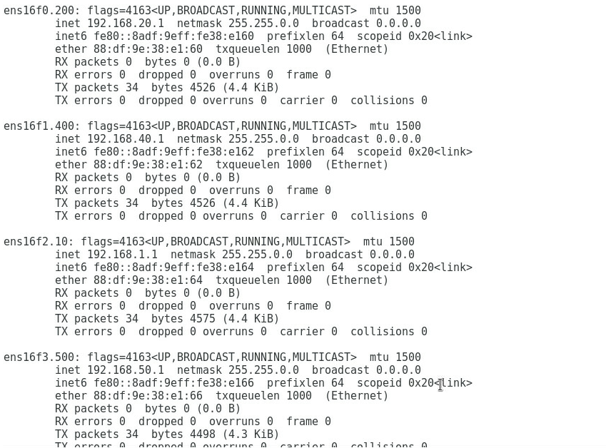
Configuring each service IP address
1. As shown in Figure 2, add Port 1, Port 2, Port 3, and Port 4 to VLAN 200, VLAN 400, VLAN 10, and VLAN 500 based on the service requirements, and configure the IP addresses 192.168.20.1, 192.168.40.1, 192.168.1.1, and 192.168.50.1, respectively.
Figure 2 Configuring the IP address of each port
Verifying the configuration
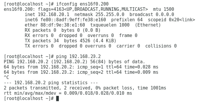
1. As shown in Figure 3, the gateway address of the R&D Department can be successfully pinged on Port 1.
Figure 3 Checking whether the network is normal on Port 1
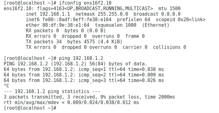
2. As shown in Figure 4, the gateway address of the Quality Department can be successfully pinged on Port 3.
Figure 4 Checking whether the network is normal on Port 3
3. As shown in Figure 5 and Figure 6, the gateway address of the Marketing Department can be successfully pinged on Port 2 and Port 4.
Figure 5 Checking whether the network is normal on Port 2

Figure 6 Checking whether the network is normal on Port 4

4. Replace the original blade server with a blade server that has the same hardware configuration and software configuration.
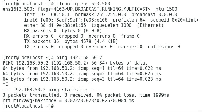
5. As shown in Figure 7, the gateway address of the R&D Department can still be successfully pinged on Port 1.
Figure 7 Checking whether the network is normal on Port 1

6. As shown in Figure 8, the gateway address of the Quality Department can still be successfully pinged on Port 3.
Figure 8 Checking whether the network is normal on Port 3

7. As shown in Figure 9, the gateway address of the Marketing Department can still be successfully pinged on Port 2 and Port 4.
Figure 9 Checking whether the network is normal on Port 2
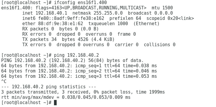
Figure 10 Checking whether the network is normal on Port 4