- Table of Contents
-
- H3C UniServer B16000 Blade Server Configuration Examples-6W100
- 01-FC and FCoE Services Configuration Examples
- 02-Ethernet Services Configuration Examples
- 03-Virtual Management Network Configuration Examples
- 04-Shared Storage Configuration Examples
- 05-VC Configuration Examples
- 06-Chassis Profile Configuration Examples
- 07-IB Service Configuration Examples
- 08-Blade Server FIST Configuration Examples
- Related Documents
-
| Title | Size | Download |
|---|---|---|
| 05-VC Configuration Examples | 4.67 MB |
Contents
Hardware compatibility and supported network types
Recommended software and hardware versions
Example: Configuring a VC profile – 1.01.xx
Procedures (from the OM Web interface)
Creating and applying Profile-1
Configuring each service IP address
Procedures (on the OM command line)
Using Profile-1 to associate different vNETs created to different ports of the Mezz NIC
Applying Profile-1 to the blade server
Configuring each service IP address
Example: Configuring a VC profile on the OM Web page – 1.02.xx or later
Creating the network profile Profile-1
Creating and applying a blade server profile
Configuring each service IP address
xample: Configuring a VC profile on the OM Web page in the QinQ scenario – 1.02.xx or later
Configuring the NPAR function for the NIC in BIOS
Configuring the FCoE function for the Mezz NIC in the operating system
Configuring the ICM in the shared uplink port network
Configuring the ICM in the tunnel network
Configuring the ICM in a common network
Configuring the FCoE network (NPV mode)
Configuring the FCoE network (FCF mode)
Configuring the connection mode of the network uplink port
Configuring the bandwidth of a network
Configuring each service IP address
Example: Configuring a VC profile on the OM Web page in the non QinQ scenario – 1.02.xx or later
Configuring the ICM in the shared uplink port network
Configuring the ICM in a common network
Configuring the connection mode of the network uplink port
Configuring each service IP address
Introduction
The following information provides examples for configuring the OM Virtual Connection (VC) feature.
Hardware compatibility and supported network types
Table 1 lists the mapping between NICs and supported networks in each typical networking. If there are multiple models in a cell, the hardware of these models is appropriate for this configuration.
The ICM can be installed in slots 1–6. You can use the networking query tool to query compatibility and internal connection between the NIC and Interconnection module (ICM).
Table 1 Mapping between NICs and supported networks
|
Network type |
Hardware compatibility |
|||
|
NIC |
ICM |
External switch |
Backend storage |
|
|
ETH |
· ETH521i · ETH522i · ETH682i · ETH640i · ETH641i · ETH561i |
· BX720EF · BX720E · BX1020EF · BX1010E |
Ethernet switch |
NA |
|
SAN |
· ETH521i · ETH522i · ETH682i · FC680i · FC730i |
· BX720EF · BX1020EF · BX608FE |
Converged network switch FC switch |
3Par storage server |
|
iSCSI |
· ETH521i · ETH522i |
· BX720EF · BX720E · BX1020EF |
NA |
3Par storage server |
Recommended software and hardware versions
The configurations vary according to the version and scenario.
OM-1.01.xx
Recommended configuration
Table 2 Recommended configuration for OM1.01.xx
|
Item |
Model or system |
Software version |
|
OM module |
OM module |
OM-1.01.15 or later |
|
ICM |
BX1020EF |
BX1020EF 1.02.12 or later |
|
NIC |
NIC-ETH682i-Mb-2*25G |
Driver version: 8.55.90.03 or later |
|
Compute node |
B5700 G3 |
· HDM: 2.57 or later · BIOS: 2.00.51 or later |
|
OS |
VMware ESXi 6.7 |
Compatible driver version: 4.0.270.0 or later |
|
Microsoft Windows Server 2016 Standard |
Compatible driver version: 8.58.10.0 or later |
Applicable configuration procedures
· From the Web interface: "Procedures (from the OM Web interface)"
· From the CLI: "Procedures (on the OM command line)"
OM 1.02.xx or later
Recommended configuration
Table 3 Recommended configuration for OM 1.02.xx or later
|
|
Model or system |
Software version |
|
OM module |
OM module |
OM-1.03.01 or later |
|
ICM |
BX1020EF |
BX1020EF 1.03.01 or later |
|
NIC |
NIC-ETH682i-Mb-2*25G |
Driver version: 8.55.90.03 or later |
|
Compute node |
B5700 G5 |
· HDM: 2.57 or later · BIOS: 2.00.51 or later |
|
OS |
VMware ESXi 6.7 |
Compatible driver version: 4.0.270.0 or later |
|
Microsoft Windows Server 2016 Standard |
Compatible driver version: 8.58.10.0 or later |
Applicable configuration procedures
· From the Web interface: "Example: Configuring a VC profile on the OM Web page – 1.02.xx or later"
· From the CLI (QinQ scenario): "xample: Configuring a VC profile on the OM Web page in the QinQ scenario – 1.02.xx or later"
· From the CLI (non QinQ scenario): "Example: Configuring a VC profile on the OM Web page in the non QinQ scenario – 1.02.xx or later"
Prerequisites
The configuration examples were created and verified in a lab environment, and all the devices were started with the factory default configuration. When you are working on a live network, make sure you understand the potential impact of every command on your network.
The following information assumes that you have understood the features, such as IRF, NPAR, QinQ, port aggregation and port isolation, and master the basic usage methods of H3C blade servers, ICM, and OS.
The following configuration examples mainly describe the configuration process on the blade chassis side. As a best practice, modify the configurations of the external network based on the actual requirements.
Example: Configuring a VC profile – 1.01.xx
Network requirements
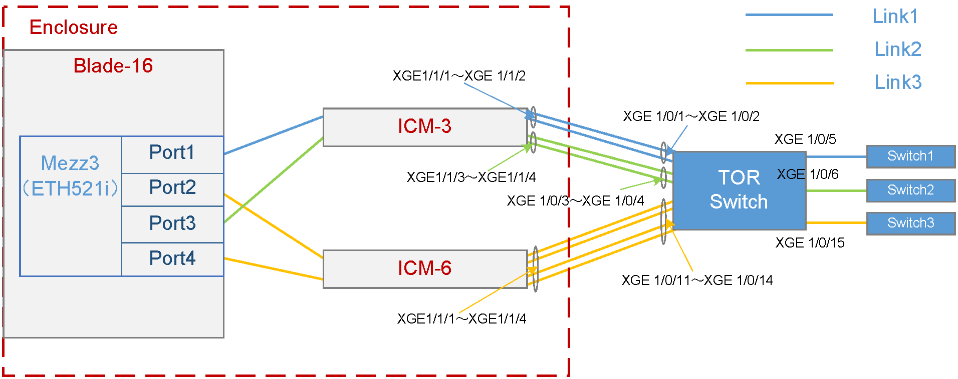
As shown in Figure 1, a blade server and an ICM are installed in the H3C UniServer B16000 blade server chassis. In this example, the blade server used is H3C UniServer B5700 G3, the Mezz NIC used is NIC-ETH521i-Mb-4*10G (ETH521i for short), and the ICM used is H3C UniServer BX720E.
· The blade server is installed in slot 16. The Mezz NIC is installed in the slot of Mezz 3 at the rear of the blade server.
· Two ICMs are installed in the slots of ICM 3 and ICM 6 respectively, and connect to the TOR switch through external ports. The external ports of ICM 3, including XGE1/1/1 (Port 1), XGE1/1/2 (Port 2), XGE1/1/3 (Port 3), and XGE1/1/4 (Port 4), are connected to the ports XGE1/0/1, XGE1/0/2, XGE1/0/3, and XGE1/0/4 of the TOR switch in turn. The external ports of ICM 6, including XGE1/1/1 (Port 1), XGE1/1/2 (Port 2), XGE1/1/3 (Port 3), and XGE1/1/4 (Port 4), are connected to the ports XGE1/0/11, XGE1/0/12, XGE1/0/13, and XGE1/0/14 of the TOR switch in turn.
· On the TOR switch, ports XGE1/0/1 and XGE1/0/2 are added to the aggregation group and allow traffic of VLAN 100 to pass through; ports XGE1/0/3 and XGE1/0/4 are added to the aggregation group and allow traffic of VLAN 10 to pass through; ports XGE1/0/11, XGE1/0/12, XGE1/0/13, and XGE1/0/14 are added to the aggregation group and allow traffic of VLAN 400 and VLAN 500 to pass through. Port XGE1/0/5 allows VLAN 100 to connect to Switch 1 (acting as the access switch of the R&D Department), port XGE1/0/6 allows VLAN 10 to connect to Switch 2 (acting as the access switch of the Quality Department), and port XGE1/0/15 allows VLAN 400 and VLAN 500 to connect to Switch 3 (acting as the access switch of the Marketing Department).
A VC profile needs to be configured so that different departments of the company can access different services on the blade server. The specific requirements are as follows:
· To ensure stability of services, back up the BIOS and RAID configurations of the blade server before service deployment, and meanwhile ensure redundancy of service data.
· Allocate the R&D Department to VLAN 100 and the gateway address is 192.168.20.2/24. This department needs to access the service resources of the blade server in VLAN 200 and the service IP address is 192.168.20.1/24.
· Allocate the Market Department to VLAN 400 and VLAN 500, and the gateway addresses are 192.168.40.2/24 and 192.168.50.2/24 respectively. This department needs to access the service resources of the blade server in VLAN 400 and VLAN 500, and the service IP addresses are 192.168.40.1/24 and 192.168.50.1/24 respectively.
· Allocate the Quality Department to VLAN 10 and the gateway address is 192.168.1.2/24. This department needs to access the service resources of the blade server in VLAN 10 and the service IP address is 192.168.1.1/24.
· To ensure reliability of external links, configure link aggregation on the uplink port (external port of the ICM) and TOR switch ports.
· After the blade server is replaced by the same type of blade server, no configuration is needed, and the original network configuration is still effective.
· The detailed port connections for the VC profile networking are shown in Table 4.
Table 4 Port connections for the VC profile networking
|
Port No. of Mezz NIC |
ICM connected through the ICM internal port |
ICM internal port No. |
Connected TOR switch port |
Networking link |
Application scenarios |
|
Port1 |
ICM-3 |
XGE1/1/1 (Port 1) |
XGE1/0/1 |
Link1 · Traffic of VLAN 200 can pass through within the chassis. · Traffic of VLAN 100 can pass through outside the chassis. · VLAN mapping is deployed on the chassis egress to map VLAN 200 to VLAN 100. |
Applicable to service scenarios requiring VLAN mapping |
|
XGE1/1/2 (Port 2) |
XGE1/0/2 |
||||
|
Port3 |
ICM-3 |
XGE1/1/3 (Port 3) |
XGE1/0/3 |
Link2 · Traffic of VLAN 10 can pass through within the chassis. · Traffic of VLAN 10 can pass through outside the chassis. |
Applicable to service scenarios requiring a single VLAN |
|
XGE1/1/4 (Port 4) |
XGE1/0/4 |
||||
|
Port2 |
ICM-6 |
XGE1/1/1 (Port 1) |
XGE1/0/11 |
Link3 · Traffic of VLAN 400 and VLAN 500 can pass through within the chassis. · Traffic of VLAN 400 and VLAN 500 can pass through outside the chassis. |
Applicable to service scenarios requiring multiple VLANs |
|
XGE1/1/2 (Port 2) |
XGE1/0/12 |
||||
|
Port4 |
ICM-6 |
XGE1/1/3 (Port 3) |
XGE1/0/13 |
||
|
XGE1/1/4 (Port 4) |
XGE1/01/4 |
Analysis
· To ensure that the R&D Department in VLAN 100 can access the service resources of the blade server in VLAN 200, Port 1 of the Mezz NIC in Blade 16 must be able to communicate with the TOR switch ports (XGE1/0/1 and XGE1/0/2) through the external port (uplink port) of ICM 3. In addition, Port 1 of Mezz NIC allows the traffic of VLAN 200 to pass through, and the TOR switch ports (XGE1/0/1 and XGE1/0/2) allow the traffic of VLAN 100 to pass through. You also need to deploy VLAN mapping in the OM to map VLAN 200 to VLAN 100.
· To ensure that the Quality Department in VLAN 10 can access the public service resources of the blade server in VLAN 10, Port 3 of the Mezz NIC in Blade 16 must be able to communicate with the TOR switch ports (XGE1/0/3 and XGE1/0/4) through the external port (uplink port) of ICM 3. In addition, Port 1 of Mezz NIC and TOR switch ports allow the traffic of VLAN 10 to pass through.
· To ensure that the Marketing Department in VLAN 400 and VLAN 500 can access the service resources of the blade server in VLAN 400 and VLAN 500, Port 2 and Port 4 of the Mezz NIC in Blade 16 must be able to communicate with the TOR switch ports (XGE1/0/11, XGE1/0/12, XGE1/0/13, and XGE1/0/14) through the external port (uplink port) of ICM 6. In addition, Port 2 and Port 4 of Mezz NIC and TOR switch ports (XGE1/0/11, XGE1/0/12, XGE1/0/13, and XGE1/0/14) allow the traffic of both VLAN 400 and VLAN 500 to pass through.
· To ensure the above service network, create a series of network profiles (vNETn), and define the VLANs allowed to pass through the network and the bound uplink ports (that is, the external ports of the ICM). For the vNET bound with VLAN ID, create different uplink shared ports (SUS-1 and SUS-2) and define the allowed VLANs. The mapping between the service network and vNET, and that between the vNET and SUS are as follows:
¡ To ensure the service requirements of the R&D Department, create vNET 1 to allow the traffic of VLAN 100 to pass through (by creating SUS-1), and bind ports TenGE1/1/1 and TenGE1/1/2 of ICM 3 as the uplink port.
¡ To ensure the service requirements of the Quality Department, create vNET 2 that works in Tunneling mode, and bind ports TenGE1/1/3 and TenGE1/1/4 of ICM 3 as the uplink port.
¡ To ensure the service requirements of the Marketing Department, create vNET 3 and vNET 4 to allow the traffic of VLAN 400 and VLAN 500 to pass through (by creating SUS-2), and bind ports TenGE1/1/1 to TenGE1/1/4 of ICM 6 as the uplink port.
· To ensure the link connection between the Mezz NIC and TOR switch ports, create a network profile Profile-1 to bind different vNETs and different Mezz NIC ports in turn.
· To improve reliability of external links, configure link aggregation on the uplink port (external port of the ICM) and TOR switch ports.
· To ensure that each department's VLAN has a gateway address, configure an IP address for each VLAN on the TOR switch as the gateway address.
· After all the configurations are completed, if the blade server is replaced, you only need to ensure that the system-side configuration (that is, the system configuration and service software configuration) of the blade server remains unchanged, and the original communication network can still be used normally.
Software versions used
In this example, data is configured and verified on the ICM (UN_BLADE-SWITCH_SYS-1.01.04) and OM (UN_BLADE-OM-1.01.07).
Procedures (from the OM Web interface)
Logging in to the OM
1. Open the browser on the PC, enter the IP address of the OM Web page (format: https://OM_ip_address). Enter the username and password of the administrator. Click Login.
Creating vNET-1
1. Select Profile Management > Shared Uplink Port > Create.
2. Configure the following parameters according to the configuration analysis:
a. Set Shared Uplink Port Name to SUS-1.
b. Set Connection Mode to Dynamic Aggregation. In the Add Port area, select the ICM in slot 3, and select two external ports, Ten-GigabitEthernet1/1/1 and Ten-GigabitEthernet1/1/2, as the uplink ports for the vNET-1 network profile.
c. In the Add Associated Network list, click Create.
3. Configure the following parameters in the Add Associated Network dialog box:
a. Set Network Addition Mode to Single.
b. Set Network Name to vNET-1.
c. Set VLAN ID to 100.
d. Click OK.
4. Click Apply.
Creating vNET-2
1. Select Profile Management > Network Setting > Create.
2. Configure the following parameters according to the configuration analysis:
a. Set Network Name to vNET-2.
b. Enable the VLAN Tunneling function.
c. Set Connection Mode to Dynamic Aggregation. In the Add Port area, select the ICM in slot 3, and select two external ports, Ten-GigabitEthernet1/1/3 and Ten-GigabitEthernet1/1/4, as the uplink ports for the vNET-2 network profile.
d. Click Apply.
Creating vNET-3 and vNET-4
1. Select Profile Management > Shared Uplink Port > Create.
2. Configure the following parameters according to the configuration analysis:
a. Set Shared Uplink Port Name to SUS-2.
b. Set Connection Mode to Dynamic Aggregation. In the Add Port area, select the ICM in slot 6, and select four external ports Ten-GigabitEthernet1/1/1, Ten-GigabitEthernet1/1/2, Ten-GigabitEthernet1/1/3, and Ten-GigabitEthernet1/1/4 as the uplink ports for the vNET-3 and vNET-4 network profiles.
c. In the Add Associated Network list, click Create.
3. Configure the following parameters in the Add Associated Network dialog box:
a. Set Network Addition Mode to Single.
b. Set Network Name to vNET-3.
c. Set VLAN ID to 400.
d. Click OK.
4. Configure the following parameters in the Add Associated Network dialog box:
a. Set Network Addition Mode to Single.
b. Set Network Name to vNET-4.
c. Set VLAN ID to 500.
d. Click OK.
5. Click Apply.
Pre-configuring the ICMs
|
|
NOTE: To ensure the normal application of the blade server profile, you need to pre-configure the ICM before configuration and application. |
1. Select Profile Management > Profile > Click here. The ICM pre-configuration window opens.
2. Select ICM-3 and ICM-6 that need to be pre-configured, enable Netconf Service, and click OK to complete the pre-configuration of the ICMs.
Creating and applying Profile-1
1. Select Profile Management > Network Setting > Create.
2. Configure the following parameters of the blade server profile according to the configuration analysis:
a. Set Name to Profile-1.
b. Set Slot No. to 3.
c. Set Type to NIC-ETH521i-Mb-4*10G.
d. Configure the networks bound to Port 1 to Port 4.
3. Configure Port 1.
a. Set Network Name to Multiple networks.
b. In the dialog box displayed, add vNET-1 to the selected network list.
c. Set Server VLAN ID to 200.
d. Click OK.
4. Configure Port 3:
a. Set Network Name to Select a network.
b. In the dialog box displayed, add vNET-2 to the selected network list.
c. Click OK.
5. Configure Port 2 and Port 4. Port 2 and Port 4 configurations are the same. The following takes Port 2 configuration as an example.
a. Set Network Name to Multiple networks.
b. In the dialog box displayed, add vNET-3 and vNET-4 to the selected network list.
c. Click OK.
6. Set Blade Server to Bay16 (B5700 G3), and click Shutdown in the Operation column.
7. Click OK in the dialog box displayed to shut down the blade server.
8. Set Create.
Configuring the TOR switch
Creating an aggregation port and allowing the traffic of VLAN 100 to pass through
# Create VLAN 100.
[H3C] vlan100
[H3C-vlan100]quit
# Create a layer-2 aggregation port, add the physical ports to the aggregation group, and allow VLAN 100 to pass.
[H3C] interface Bridge-Aggregation 10
[H3C-Bridge-Aggregation10]
[H3C-Bridge-Aggregation10]link-aggregation mode dynamic
[H3C] interface Ten-GigabitEthernet 1/0/1
[H3C-Ten-GigabitEthernet1/0/1] port link-aggregation group 10
[H3C-Ten-GigabitEthernet1/0/1] quit
[H3C] interface Ten-GigabitEthern 1/0/2
[H3C-Ten-GigabitEthernet1/0/2] port link-aggregation group 10
[H3C-Ten-GigabitEthernet1/0/2] quit
[H3C] interface Bridge-Aggregation 10
[H3C-Bridge-Aggregation10] port link-type trunk
[H3C-Bridge-Aggregation10] port trunk permit vlan 100
[H3C-Bridge-Aggregation10] quit
# You can view the information about the aggregation port and confirm that the aggregation port has been created.
[H3C] display link-aggregation verbose Bridge-Aggregation 10
Loadsharing Type: Shar -- Loadsharing, NonS -- Non-Loadsharing
Port Status: S -- Selected, U -- Unselected, I -- Individual
Port: A -- Auto port, M -- Management port, R -- Reference port
Flags: A -- LACP_Activity, B -- LACP_Timeout, C -- Aggregation,
D -- Synchronization, E -- Collecting, F -- Distributing,
G -- Defaulted, H -- Expired
Aggregate Interface: Bridge-Aggregation10
Aggregation Mode: dynamic
Loadsharing Type: Shar
Management VLANs: None
Port Status Priority Oper-Key
XGE1/0/1 S 32768 1
XGE1/0/2 S 32768 1
# Create a VLAN port and set the IP address of the port to 192.168.20.2/24.
[H3C] interface vlan 100
[H3C-Vlan-interface100] ip address 192.168.20.2 255.255.255.0
[H3C-Vlan-interface100] quit
# Check the VLAN interface status and confirm that the interface is UP.
[H3C-Vlan-interface2]display interface vlan 100 brief
Brief information on interfaces in route mode:
Link: ADM - administratively down; Stby - standby
Protocol: (s) - spoofing
Interface Link Protocol Primary IP Description
Vlan100 UP UP 192.168.20.2
# Save the configuration.
[H3C] save
The current configuration will be written to the device. Are you sure? [Y/N]:y
Please input the file name(*.cfg)[flash:/startup.cfg]
(To leave the existing filename unchanged, press the enter key):
Creating an aggregation port and allow the traffic of all VLANs to pass through
# Create VLAN 10.
[H3C] vlan 10
# Create a L2 aggregation port, add the physical port to the aggregation group, and allow the traffic of VLAN 10 to pass through.
[H3C] interface Bridge-Aggregation 20
[H3C-Bridge-Aggregation20]
[H3C-Bridge-Aggregation20]link-aggregation mode dynamic
[H3C] interface Ten-GigabitEthernet 1/0/3
[H3C-Ten-GigabitEthernet1/0/3] port link-aggregation group 20
[H3C-Ten-GigabitEthernet1/0/3] quit
[H3C] interface Ten-GigabitEthern 1/0/4
[H3C-Ten-GigabitEthernet1/0/4] port link-aggregation group 20
[H3C-Ten-GigabitEthernet1/0/4] quit
[H3C] interface Bridge-Aggregation 20
[H3C-Bridge-Aggregation20] port link-type trunk
[H3C-Bridge-Aggregation20] port trunk permit vlan 10
[H3C-Bridge-Aggregation20] quit
# You can view the information about the aggregation port and confirm that the aggregation port has been created.
[H3C] display link-aggregation verbose Bridge-Aggregation 20
Loadsharing Type: Shar -- Loadsharing, NonS -- Non-Loadsharing
Port Status: S -- Selected, U -- Unselected, I -- Individual
Port: A -- Auto port, M -- Management port, R -- Reference port
Flags: A -- LACP_Activity, B -- LACP_Timeout, C -- Aggregation,
D -- Synchronization, E -- Collecting, F -- Distributing,
G -- Defaulted, H -- Expired
Aggregate Interface: Bridge-Aggregation10
Aggregation Mode: dynamic
Loadsharing Type: Shar
Management VLANs: None
Port Status Priority Oper-Key
XGE1/0/3 S 32768 1
XGE1/0/4 S 32768 1
# Create any VLAN interface, and set the IP address of this interface to 192.168.1.2/24.
[H3C] interface vlan 10
[H3C-Vlan-interface10] ip address 192.168.1.2 255.255.255.0
[H3C-Vlan-interface10] quit
# Check the VLAN interface status and confirm that the interface is UP.
[H3C-Vlan-interface1]display interface vlan 10 brief
Brief information on interfaces in route mode:
Link: ADM - administratively down; Stby - standby
Protocol: (s) - spoofing
Interface Link Protocol Primary IP Description
Vlan10 UP UP 192.168.1.2
# Save the configuration.
[H3C] save
The current configuration will be written to the device. Are you sure? [Y/N]:y
Please input the file name(*.cfg)[flash:/startup.cfg]
(To leave the existing filename unchanged, press the enter key):
Creating an aggregation port and allowing the traffic of VLAN 400 and VLAN 500 to pass through
# Create VLAN 400 and VLAN 500.
[H3C] vlan400
[H3C-vlan400]quit
[H3C] vlan500
[H3C-vlan500]quit
# Create a L2 aggregation port, add the physical port to the aggregation group, and allow the traffic of VLAN 400 and VLAN 500 to pass through.
[H3C] interface Bridge-Aggregation 30
[H3C-Bridge-Aggregation30]
[H3C-Bridge-Aggregation20]link-aggregation mode dynamic
[H3C] interface Ten-GigabitEthernet 1/0/11
[H3C-Ten-GigabitEthernet1/0/11] port link-aggregation group 30
[H3C-Ten-GigabitEthernet1/0/11] quit
[H3C] interface Ten-GigabitEthern 1/0/12
[H3C-Ten-GigabitEthernet1/0/12] port link-aggregation group 30
[H3C-Ten-GigabitEthernet1/0/12] quit
[H3C] interface Ten-GigabitEthernet 1/0/13
[H3C-Ten-GigabitEthernet1/0/13] port link-aggregation group 30
[H3C-Ten-GigabitEthernet1/0/13] quit
[H3C] interface Ten-GigabitEthern 1/0/14
[H3C-Ten-GigabitEthernet1/0/14] port link-aggregation group 30
[H3C-Ten-GigabitEthernet1/0/14] quit
[H3C] interface Bridge-Aggregation 30
[H3C-Bridge-Aggregation30] port link-type trunk
[H3C-Bridge-Aggregation30] port trunk permit vlan 400 500
[H3C-Bridge-Aggregation30] quit
# You can view the information about the aggregation port and confirm that the aggregation port has been created.
[H3C] display link-aggregation verbose Bridge-Aggregation 30
Loadsharing Type: Shar -- Loadsharing, NonS -- Non-Loadsharing
Port Status: S -- Selected, U -- Unselected, I -- Individual
Port: A -- Auto port, M -- Management port, R -- Reference port
Flags: A -- LACP_Activity, B -- LACP_Timeout, C -- Aggregation,
D -- Synchronization, E -- Collecting, F -- Distributing,
G -- Defaulted, H -- Expired
Aggregate Interface: Bridge-Aggregation30
Aggregation Mode: dynamic
Loadsharing Type: Shar
Management VLANs: None
Port Status Priority Oper-Key
XGE1/0/11 S 32768 1
XGE1/0/12 S 32768 1
XGE1/0/13 S 32768 1
XGE1/0/14 S 32768 1
# Create two VLAN interfaces, and set the IP addresses of these interfaces to 192.168.40.2/24 and 192.168.50.2/24.
[H3C] interface vlan 400
[H3C-Vlan-interface400] ip address 192.168.40.2 255.255.255.0
[H3C-Vlan-interface400] quit
[H3C] interface vlan 500
[H3C-Vlan-interface500] ip address 192.168.50.2 255.255.255.0
[H3C-Vlan-interface500] quit
# Check the VLAN interface status and confirm that the interface is UP.
[H3C] interface vlan 400
[H3C-Vlan-interface400]display interface vlan 400 brief
Brief information on interfaces in route mode:
Link: ADM - administratively down; Stby - standby
Protocol: (s) - spoofing
Interface Link Protocol Primary IP Description
Vlan400 UP UP 192.168.40.2
[H3C] interface vlan 500
[H3C-Vlan-interface500]display interface vlan 500 brief
Brief information on interfaces in route mode:
Link: ADM - administratively down; Stby - standby
Protocol: (s) - spoofing
Interface Link Protocol Primary IP Description
Vlan500 UP UP 192.168.50.2
# Save the configuration.
[H3C] save
The current configuration will be written to the device. Are you sure? [Y/N]:y
Please input the file name(*.cfg)[flash:/startup.cfg]
(To leave the existing filename unchanged, press the enter key):
Configuring each service IP address
Query the interface connection between Mezz NICs and ICMs
Please use the H3C networking query tool on the official website to view the port connection relation between mezzanine cards and interconnect modules.
Querying the MAC address of the Mezz NIC
Log in to the OM Web page, select Blade Server Management, click the target blade server, and click Port Mapping to view the MAC address of the port on the Mezz NIC.
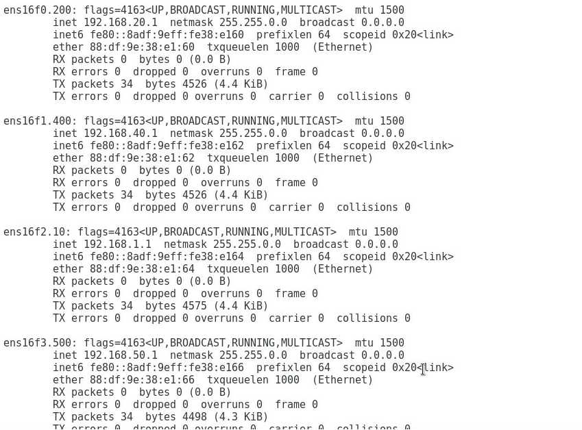
Querying the port correspondence between the network adapter and the mezzanine card under the OS
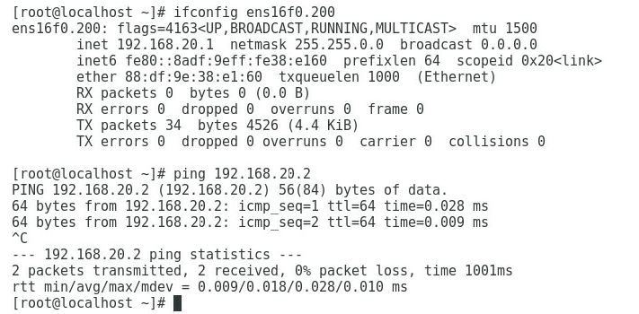
1. Execute the ifconfig command in the Linux operating system to view the MAC addresses of all NICs.
2. Obtain the relationship between the NIC in the OS and the Mezz NIC port based on the MAC address queried in the previous step.
Configuring each service IP address
1. As shown in Figure 2, add Port 1, Port 2, Port 3, and Port 4 to VLAN 200, VLAN 400, VLAN 10, and VLAN 500, and configure the IP addresses 192.168.20.1, 192.168.40.1, 192.168.1.1, and 192.168.50.1, respectively.
Figure 2 Configuring the IP address of each port
Procedures (on the OM command line)
Logging in to the OM
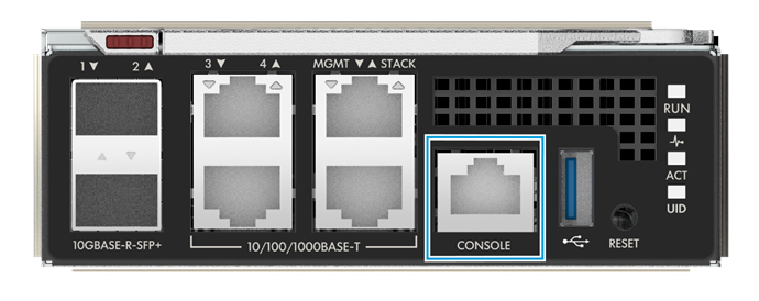
1. Use a DB9-RJ45 cable to connect the RS-232 serial port of the PC with the serial port marked Console on the OM, as shown in Figure 3.
Figure 3 Connecting the PC to the Console port of the OM
2. Set the login parameters in the remote login software, and log in to the OM command line. Login parameters are shown in Table 5.
|
Numerical value |
|
|
Serial Line to connect to |
COMn. n, integer, stands for the serial port number. Its specific value is determined by users' actual situations. |
|
Speed (baud) |
9600 |
|
Data bits |
8 |
|
Stop bits |
1 |
|
Parity |
None |
|
Flow control |
None |
3. When the login completes, the following login page appears on the OM CLI.
******************************************************************************
* Copyright (c) 2004-2020 New H3C Technologies Co., Ltd. All rights reserved.*
* Without the owner's prior written consent, *
* no decompiling or reverse-engineering shall be allowed. *
******************************************************************************
<OM>
Creating SUS-1
1. Execute the policy sus command to define a SUS named SUS-1, and set the connection mode of the uplink port bound to this SUS to the dynamic link aggregation mode.
<OM>policy sus SUS-1 connection-mode agg-dynamic
2. Execute the policy uplinkport command to associate TenGE1/1/1 (Port 1) and TenGE1/1/2 (Port 2) of ICM 3 with SUS-1.
<OM>policy uplinkport sus SUS-1 io 3 port 1
<OM>policy uplinkport sus SUS-1 io 3 port 2
Creating vNET-1
1. Execute the policy network ethernet vlan command to create an Ethernet vNET-1 bound with VLAN 100 and associate it with SUS-1.
<OM>policy network ethernet vNET-1 vlan 100 sus SUS-1
Creating vNET-2
1. Execute the policy network ethernet command to create an Ethernet vNET-2 that is not bound to any VLAN ID. In addition, enable the Tunneling function, and set the connection mode of the uplink port bound to this Ethernet to the dynamic link aggregation mode.
<OM>policy network ethernet vNET-2 tunneling enable connection-mode agg-dynamic
2. Execute the policy uplinkport command to associate TenGE1/1/3 (Port 3) and TenGE1/1/4 (Port 4) of ICM 3 with vNET-2.
<OM>policy uplinkport network vNET-2 io 3 port 3
<OM>policy uplinkport network vNET-2 io 3 port 4
Creating SUS-2
1. Execute the policy sus command to define a SUS named SUS-2, and set the connection mode of the uplink port bound to this SUS to the dynamic link aggregation mode.
<OM>policy sus SUS-2 connection-mode agg-dynamic
2. Execute the policy uplinkport command to associate TenGE1/1/1 (Port 1), TenGE1/1/2 (Port 2), TenGE1/1/3 (Port 3), TenGE1/1/4 (Port 4) of ICM 6 with SUS-2.
<OM>policy uplinkport sus SUS-2 io 6 port 1
<OM>policy uplinkport sus SUS-2 io 6 port 2
<OM>policy uplinkport sus SUS-2 io 6 port 3
<OM>policy uplinkport sus SUS-2 io 6 port 4
Creating vNET-3 and vNET-4
1. Execute the policy network ethernet vlan command to create an Ethernet vNET-3 bound with VLAN 400 and associate it with SUS-2.
<OM>policy network ethernet vNET-3 vlan 400 sus SUS-2
2. Execute the policy network ethernet vlan command to create an Ethernet vNET-4 bound with VLAN 500 and associate it with SUS-2.
<OM>policy network ethernet vNET-4 vlan 500 sus SUS-2
Pre-configuring the ICMs
|
|
NOTE: To ensure the normal application of the blade server profile, you need to pre-configure the ICM before application. |
Execute the policy preconfigured io command to pre-configure ICM 3 and ICM 6.
<OM>policy preconfigured io 3
<OM>policy preconfigured io 6
Creating Profile-1
Execute the policy profile profile-name mezz mezz-id [ type { ETH521i | ETH522i | ETH682i | FC680i } ] [ port port-id speed { auto | customer min min-bandwidth max max-bandwidth } ] &<1-16> command to create a profile named Profile-1. Set the slot No. of the Mezz NIC to 1, the type to ETH521i, and the port rate of Port 1, Port 2, Port 3, and Port 4 of the Mezz NIC to the auto negotiation mode.
<OM>policy profile Profile-1 mezz 1 type eth521i port 1 speed auto port 2 speed auto port 3 speed auto port 4 speed auto
Using Profile-1 to associate different vNETs created to different ports of the Mezz NIC
1. Execute the policy profile profile-name mezz mezz-id port port-id network ethernet [ tunnel ] netname [ untagged | server_vlan server_vlanid ] command to associate vNET-1 to Port 1 of the Mezz NIC, and set the VLAN of the blade server to VLAN 200. That is, map VLAN 200 of the blade server to VLAN 100 bound with vNET-1.
<OM>policy profile Profile-1 mezz 1 port 1 network ethernet vNET-1 server_vlan 200
2. Execute the policy profile profile-name mezz mezz-id port port-id network ethernet [ tunnel ] netname command to associate vNET-2 to Port 3 of the Mezz NIC.
<OM>policy profile Profile-1 mezz 1 port 3 network ethernet tunnel vNET-2
3. Execute the policy profile profile-name mezz mezz-id port port-id network ethernet [ tunnel ] netname command to associate vNET-2 to Port 3 of the Mezz NIC, without mapping VLANs.
<OM>policy profile Profile-1 mezz 1 port 2 network ethernet vNET-3 untagged
<OM>policy profile Profile-1 mezz 1 port 2 network ethernet vNET-4 untagged
<OM>policy profile Profile-1 mezz 1 port 4 network ethernet vNET-3 untagged
<OM>policy profile Profile-1 mezz 1 port 4 network ethernet vNET-4 untagged
Applying Profile-1 to the blade server
1. Execute the policy profile profile-name { blade-id blade-id | blade-model { b5700 | b7800 | b5800 } }* command to apply Profile-1 to the B5700 blade server in slot 16.
<OM>policy profile Profile-1 blade-id 16 blade-model b5700
Configuring the TOR switch
Creating an aggregation port and allowing the traffic of VLAN 100 to pass through
# Create VLAN 100.
[H3C] vlan100
[H3C-vlan100]quit
# Create a layer-2 aggregation port, add the physical ports to the aggregation group, and allow VLAN 100 to pass.
[H3C] interface Bridge-Aggregation 10
[H3C-Bridge-Aggregation10]
[H3C-Bridge-Aggregation10]link-aggregation mode dynamic
[H3C] interface Ten-GigabitEthernet 1/0/1
[H3C-Ten-GigabitEthernet1/0/1] port link-aggregation group 10
[H3C-Ten-GigabitEthernet1/0/1] quit
[H3C] interface Ten-GigabitEthern 1/0/2
[H3C-Ten-GigabitEthernet1/0/2] port link-aggregation group 10
[H3C-Ten-GigabitEthernet1/0/2] quit
[H3C] interface Bridge-Aggregation 10
[H3C-Bridge-Aggregation10] port link-type trunk
[H3C-Bridge-Aggregation10] port trunk permit vlan 100
[H3C-Bridge-Aggregation10] quit
# You can view the information about the aggregation port and confirm that the aggregation port has been created.
[H3C] display link-aggregation verbose Bridge-Aggregation 10
Loadsharing Type: Shar -- Loadsharing, NonS -- Non-Loadsharing
Port Status: S -- Selected, U -- Unselected, I -- Individual
Port: A -- Auto port, M -- Management port, R -- Reference port
Flags: A -- LACP_Activity, B -- LACP_Timeout, C -- Aggregation,
D -- Synchronization, E -- Collecting, F -- Distributing,
G -- Defaulted, H -- Expired
Aggregate Interface: Bridge-Aggregation10
Aggregation Mode: dynamic
Loadsharing Type: Shar
Management VLANs: None
Port Status Priority Oper-Key
XGE1/0/1 S 32768 1
XGE1/0/2 S 32768 1
# Create a VLAN port and set the IP address of the port to 192.168.20.2/24.
[H3C] interface vlan 100
[H3C-Vlan-interface100] ip address 192.168.20.2 255.255.255.0
[H3C-Vlan-interface100] quit
# Check the VLAN interface status and confirm that the interface is UP.
[H3C-Vlan-interface2]display interface vlan 100 brief
Brief information on interfaces in route mode:
Link: ADM - administratively down; Stby - standby
Protocol: (s) - spoofing
Interface Link Protocol Primary IP Description
Vlan100 UP UP 192.168.20.2
# Save the configuration.
[H3C] save
The current configuration will be written to the device. Are you sure? [Y/N]:y
Please input the file name(*.cfg)[flash:/startup.cfg]
(To leave the existing filename unchanged, press the enter key):
Creating an aggregation port and allow the traffic of all VLANs to pass through
# Create VLAN 10.
[H3C] vlan 10
# Create a L2 aggregation port, add the physical port to the aggregation group, and allow the traffic of VLAN 10 to pass through.
[H3C] interface Bridge-Aggregation 20
[H3C-Bridge-Aggregation20]
[H3C-Bridge-Aggregation20]link-aggregation mode dynamic
[H3C] interface Ten-GigabitEthernet 1/0/3
[H3C-Ten-GigabitEthernet1/0/3] port link-aggregation group 20
[H3C-Ten-GigabitEthernet1/0/3] quit
[H3C] interface Ten-GigabitEthern 1/0/4
[H3C-Ten-GigabitEthernet1/0/4] port link-aggregation group 20
[H3C-Ten-GigabitEthernet1/0/4] quit
[H3C] interface Bridge-Aggregation 20
[H3C-Bridge-Aggregation20] port link-type trunk
[H3C-Bridge-Aggregation20] port trunk permit vlan 10
[H3C-Bridge-Aggregation20] quit
# You can view the information about the aggregation port and confirm that the aggregation port has been created.
[H3C] display link-aggregation verbose Bridge-Aggregation 20
Loadsharing Type: Shar -- Loadsharing, NonS -- Non-Loadsharing
Port Status: S -- Selected, U -- Unselected, I -- Individual
Port: A -- Auto port, M -- Management port, R -- Reference port
Flags: A -- LACP_Activity, B -- LACP_Timeout, C -- Aggregation,
D -- Synchronization, E -- Collecting, F -- Distributing,
G -- Defaulted, H -- Expired
Aggregate Interface: Bridge-Aggregation10
Aggregation Mode: dynamic
Loadsharing Type: Shar
Management VLANs: None
Port Status Priority Oper-Key
XGE1/0/3 S 32768 1
XGE1/0/4 S 32768 1
# Create any VLAN interface, and set the IP address of this interface to 192.168.1.2/24.
[H3C] interface vlan 10
[H3C-Vlan-interface10] ip address 192.168.1.2 255.255.255.0
[H3C-Vlan-interface10] quit
# Check the VLAN interface status and confirm that the interface is UP.
[H3C-Vlan-interface1]display interface vlan 10 brief
Brief information on interfaces in route mode:
Link: ADM - administratively down; Stby - standby
Protocol: (s) - spoofing
Interface Link Protocol Primary IP Description
Vlan10 UP UP 192.168.1.2
# Save the configuration.
[H3C] save
The current configuration will be written to the device. Are you sure? [Y/N]:y
Please input the file name(*.cfg)[flash:/startup.cfg]
(To leave the existing filename unchanged, press the enter key):
Creating an aggregation port and allowing the traffic of VLAN 400 and VLAN 500 to pass through
# Create VLAN 400 and VLAN 500.
[H3C] vlan400
[H3C-vlan400]quit
[H3C] vlan500
[H3C-vlan500]quit
# Create a L2 aggregation port, add the physical port to the aggregation group, and allow the traffic of VLAN 400 and VLAN 500 to pass through.
[H3C] interface Bridge-Aggregation 30
[H3C-Bridge-Aggregation30]
[H3C-Bridge-Aggregation20]link-aggregation mode dynamic
[H3C] interface Ten-GigabitEthernet 1/0/11
[H3C-Ten-GigabitEthernet1/0/11] port link-aggregation group 30
[H3C-Ten-GigabitEthernet1/0/11] quit
[H3C] interface Ten-GigabitEthern 1/0/12
[H3C-Ten-GigabitEthernet1/0/12] port link-aggregation group 30
[H3C-Ten-GigabitEthernet1/0/12] quit
[H3C] interface Ten-GigabitEthernet 1/0/13
[H3C-Ten-GigabitEthernet1/0/13] port link-aggregation group 30
[H3C-Ten-GigabitEthernet1/0/13] quit
[H3C] interface Ten-GigabitEthern 1/0/14
[H3C-Ten-GigabitEthernet1/0/14] port link-aggregation group 30
[H3C-Ten-GigabitEthernet1/0/14] quit
[H3C] interface Bridge-Aggregation 30
[H3C-Bridge-Aggregation30] port link-type trunk
[H3C-Bridge-Aggregation30] port trunk permit vlan 400 500
[H3C-Bridge-Aggregation30] quit
# You can view the information about the aggregation port and confirm that the aggregation port has been created.
[H3C] display link-aggregation verbose Bridge-Aggregation 30
Loadsharing Type: Shar -- Loadsharing, NonS -- Non-Loadsharing
Port Status: S -- Selected, U -- Unselected, I -- Individual
Port: A -- Auto port, M -- Management port, R -- Reference port
Flags: A -- LACP_Activity, B -- LACP_Timeout, C -- Aggregation,
D -- Synchronization, E -- Collecting, F -- Distributing,
G -- Defaulted, H -- Expired
Aggregate Interface: Bridge-Aggregation30
Aggregation Mode: dynamic
Loadsharing Type: Shar
Management VLANs: None
Port Status Priority Oper-Key
XGE1/0/11 S 32768 1
XGE1/0/12 S 32768 1
XGE1/0/13 S 32768 1
XGE1/0/14 S 32768 1
# Create two VLAN interfaces, and set the IP addresses of these interfaces to 192.168.40.2/24 and 192.168.50.2/24.
[H3C] interface vlan 400
[H3C-Vlan-interface400] ip address 192.168.40.2 255.255.255.0
[H3C-Vlan-interface400] quit
[H3C] interface vlan 500
[H3C-Vlan-interface500] ip address 192.168.50.2 255.255.255.0
[H3C-Vlan-interface500] quit
# Check the VLAN interface status and confirm that the interface is UP.
[H3C] interface vlan 400
[H3C-Vlan-interface400]display interface vlan 400 brief
Brief information on interfaces in route mode:
Link: ADM - administratively down; Stby - standby
Protocol: (s) - spoofing
Interface Link Protocol Primary IP Description
Vlan400 UP UP 192.168.40.2
[H3C] interface vlan 500
[H3C-Vlan-interface500]display interface vlan 500 brief
Brief information on interfaces in route mode:
Link: ADM - administratively down; Stby - standby
Protocol: (s) - spoofing
Interface Link Protocol Primary IP Description
Vlan500 UP UP 192.168.50.2
# Save the configuration.
[H3C] save
The current configuration will be written to the device. Are you sure? [Y/N]:y
Please input the file name(*.cfg)[flash:/startup.cfg]
(To leave the existing filename unchanged, press the enter key):
Configuring each service IP address
Query the interface connection between Mezz NICs and ICMs
Please use the H3C networking query tool on the official website to view the port connection relation between mezzanine cards and interconnect modules.
Querying the MAC address of the Mezz NIC
Log in to the OM Web page, select Blade Server Management, click the target blade server, and click Port Mapping to view the MAC address of the port on the Mezz NIC.
Querying the port correspondence between the network adapter and the mezzanine card under the OS
1. Execute the ifconfig command in the Linux operating system to view the MAC addresses of all NICs.
2. Obtain the relationship between the NIC in the OS and the Mezz NIC port based on the MAC address queried in the previous step.
Configuring each service IP address
As shown in Figure 4, add Port 1, Port 2, Port 3, and Port 4 to VLAN 200, VLAN 400, VLAN 10, and VLAN 500, and configure the IP addresses 192.168.20.1, 192.168.40.1, 192.168.1.1, and 192.168.50.1, respectively.
Figure 4 Configuring the IP address of each port

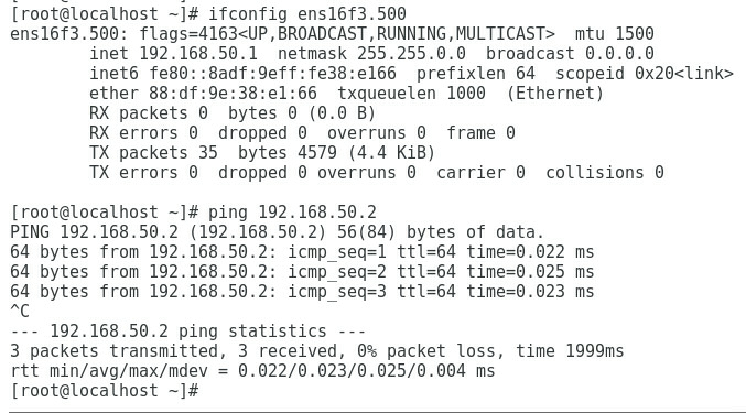
Verifying the configuration
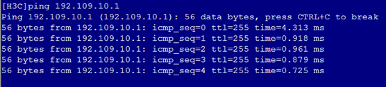
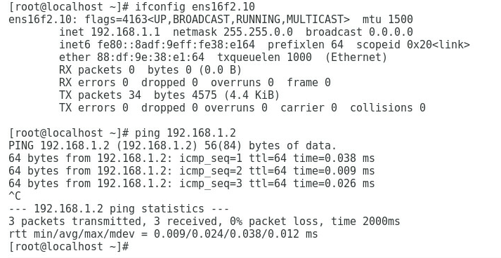
1. As shown in Figure 5, the gateway address of the R&D Department can be successfully pinged on Port 1.
Figure 5 Checking whether the network is normal on Port 1

2. As shown in Figure 6, the gateway address of the Quality Department can be successfully pinged on Port 3.
Figure 6 Checking whether the network is normal on Port 3
3. As shown in Figure 7 and Figure 8, the gateway address of the Marketing Department can be successfully pinged on Port 2 and Port 4.
Figure 7 Checking whether the network is normal on Port 2

Figure 8 Checking whether the network is normal on Port 4

4. Replace the original blade server with a blade server that has the same hardware configuration and software configuration.
5. As shown in Figure 9, the gateway address of the R&D Department can still be successfully pinged on Port 1.
Figure 9 Checking whether the network is normal on Port 1

6. As shown in Figure 10, the gateway address of the Quality Department can still be successfully pinged on Port 3.
Figure 10 Checking whether the network is normal on Port 3

7. As shown in Figure 11, the gateway address of the Marketing Department can still be successfully pinged on Port 2 and Port 4.
Figure 11 Checking whether the network is normal on Port 2
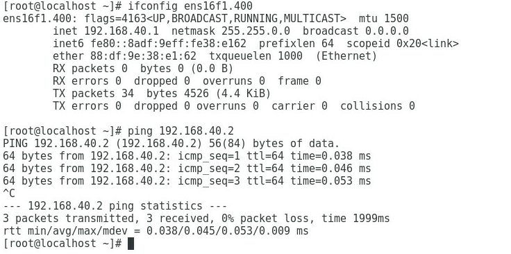
Figure 12 Checking whether the network is normal on Port 4

Example: Configuring a VC profile on the OM Web page – 1.02.xx or later
Network requirements
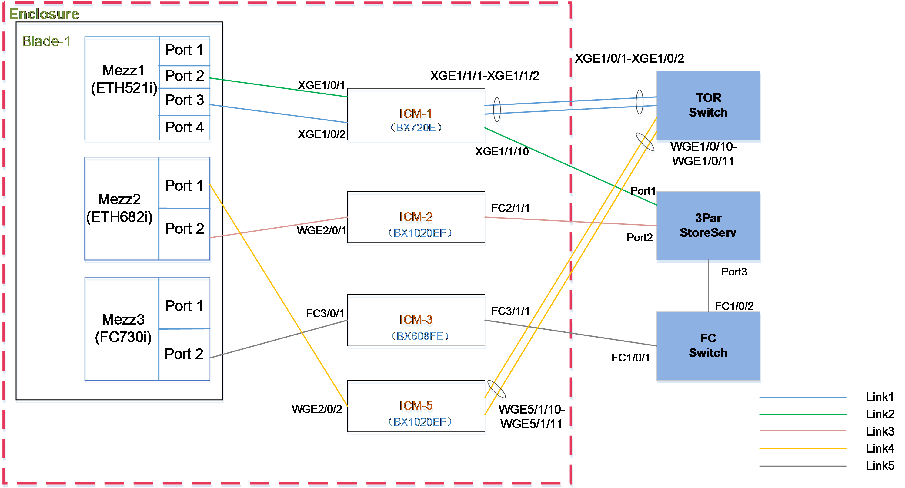
As shown in Figure 13, a blade server and an ICM are installed in the H3C UniServer B16000 blade server chassis. In this example, the network configuration is as follows:
· The model of TOR switch used in the network is H3C S5820V2-52QF.
· The blade server H3C UniServer B5700 G3 (hereinafter referred to as 5700 G3) is installed in slot 1. For Mezz NICs at the rear of the blade server, NIC-ETH521i-Mb-4*10G (hereinafter referred to as ETH521i) is installed in slot 1, NIC-ETH682i-Mb-2*25G (hereinafter referred to as ETH682i) is installed in slot 2, and NIC-FC730i-Mb-2*32G (hereinafter referred to as FC730i) is installed in slot 3.
· BX720E is inserted to the slot of ICM 1. The ICM 1 ports XGE1/1/1 and XGE1/1/2 are connected to ports XGE1/0/1 and XGE1/0/2 of the TOR switch respectively; XGE1/1/10 is connected to Port 1 of the 3Par storage server.
· BX1020EFs are inserted to the slots of ICM 2 and ICM 5. The ICM 2 port FC2/1/1 is connected to Port 2 of the 3Par storage server; ICM 5 ports WGE5/1/10 and WGE5/1/11 are respectively connected to ports WGE1/0/10 and WGE1/0/11 of the TOR switch.
· BX608EF is inserted in the slot of ICM 3. The ICM 3 port FC3/1/1 is connected to the FC1/0/1 port of the FC switch.
· The TOR switch ports XGE1/0/1 and XGE1/0/2 are member ports of a SmartLink group and allow the traffic of VLAN 100 to pass through. Ports XGE1/0/10 and XGE1/0/11 are added to an aggregation group and allow the traffic of VLAN400 and VLAN500 to pass through. Port XGE1/0/5 allows the traffic of VLAN 100 to pass through and connects to Switch 1, and port XGE1/0/12 allows the traffic of VLAN 400 and VLAN 500 to pass through and connects to Switch 3.
· Port 1 on the 3Par storage server can be mounted to Blade 1 through the iSCSI network, Port 2 can be mounted to Blade 1 through the FCoE network, and Port 3 can be mounted to Blade 1 through the FC network.
· The FC switch connects the link between the 3Par storage server and ICM 3 through FC1/0/1 and FC1/0/2.
A chassis profile needs to be configured so that different departments of the company can access different services on the blade server. The specific requirements are as follows:
· Allocate the R&D Department to VLAN 100 and the gateway address is 192.168.20.2/24. This department needs to access the service resources of the blade server in VLAN 200 through Link 1 and the service IP address is 192.168.20.1/24.
· Allocate the Marketing Department to VLAN 400 and VLAN 500 and the gateway addresses are 192.168.40.2/24 and 192.168.50.2/24. This department needs to access the service resources of the blade server in VLAN 400 and VLAN 500 through Link 4 and the service IP addresses are 192.168.40.1/24 and 192.168.50.1/24.
· The remote storage can be loaded to Blade 1 through Link 2, Link 3, and Link 5 to expand the capacity of the device.
· To ensure reliability of external links, configure link aggregation on the uplink port (external port of the ICM) and TOR switch ports.
· After the blade server is replaced by the same type of blade server, no configuration is needed, and the original network configuration is still effective.
· The detailed port connections for the chassis profile networking are shown in Table 6.
Table 6 Port connections for the chassis profile networking
|
Port No. of Mezz NIC |
Connection between Mezz NIC ports and ICMs |
ICM internal port No. |
External device connected |
Networking link |
Application scenarios |
|
Mezz1 (Port 2) |
ICM-1 XGE1/0/1 |
XGE1/1/10 |
Port 1 of the 3Par storage server |
Link2 iSCSI network |
Storage capacity expansion of the device |
|
Mezz1 (port3) |
ICM-1 XGE1/0/2 |
XGE1/1/1 |
TOR switch XGE1/0/1 |
Link1 · Traffic of VLAN 200 can pass through within the chassis. · Traffic of VLAN 100 can pass through outside the chassis. · VLAN mapping is deployed on the chassis egress to map VLAN 200 to VLAN 100. |
Applicable to service scenarios requiring VLAN mapping |
|
XGE1/1/2 |
TOR switch XGE1/0/2 |
||||
|
Mezz2 (port1) |
ICM-5 WGE2/0/2 |
WGE5/1/10 |
TOR switch WGE1/0/10 |
Link4 · Traffic of VLAN 400 and VLAN 500 can pass through within the chassis. · Traffic of VLAN 400 and VLAN 500 can pass through outside the chassis. |
Applicable to service scenarios requiring multiple networks |
|
WGE5/1/11 |
TOR switch WGE1/0/11 |
||||
|
Mezz2 (Port 2) |
ICM-2 WGE2/0/1 |
FC2/1/1 |
Port 2 of the 3Par storage server |
Link3 FCF network |
Storage capacity expansion of the device |
|
Mezz3 (Port 2) |
ICM-3 FC3/0/1 |
FC3/1/1 |
FC switch FC1/0/1 |
Link5 NPV network |
Storage capacity expansion of the device |
Analysis
· To ensure that the R&D Department in VLAN 100 can access the service resources of the blade server in VLAN 200, Port 3 of Mezz 1 in Blade must be able to communicate with the TOR switch ports (XGE1/0/1 and XGE1/0/2) through the external port (uplink port) of ICM 1. In addition, Port 3 of Mezz 1 allows the traffic of VLAN 200 to pass through, and the TOR switch ports (XGE1/0/1 and XGE1/0/2) allow the traffic of VLAN 100 to pass through. You also need to deploy VLAN mapping in the OM to map VLAN 200 to VLAN 100.
· To ensure that the Marketing Department in VLAN 400 and VLAN 500 can access the service resources of the blade server in VLAN 400 and VLAN 500, Port 1 of Mezz 2 in Blade 1 must be able to communicate with the TOR switch ports (WGE1/0/10 and WGE1/0/11) through the external port (uplink port) of ICM 5. In addition, Port 2 of Mezz 2 allows the traffic of VLAN 400 and VLAN 500 to pass through, and TOR switch ports (WGE1/0/10 and WGE1/0/11) also allow the traffic of VLAN 400 and VLAN 500 to pass through.
· To ensure that the 3Par remote storage can be mounted to Blade 1, Link 2, Link 3, and Link 5 must be connected.
· To configure the network as a non-QinQ network and ensure the normal application of the blade server profile, pre-configure all ICMs and set them to the non-QinQ mode.
· To ensure the above service network, create a series of network profiles (vNETn), SAN network profiles, and iSCSI network profiles, and define the VLANs allowed to pass through the network and the bound uplink ports (that is, the external ports of the ICM). For the vNET bound with VLAN ID, create different uplink shared ports (SUS-1 and SUS-2) and define the allowed VLANs. The mapping between the service network and vNET, and that between the vNET and SUS are as follows:
¡ To ensure the service requirements of the R&D Department, create vNET 1 to allow the traffic of VLAN 100 to pass through (by creating SUS-1), and bind ports TenGE1/1/1 and TenGE1/1/2 of ICM 1 as the uplink port.
¡ To ensure the service requirements of the Marketing Department, create vNET 2 and vNET 3 to allow the traffic of VLAN 400 and VLAN 500 to pass through (by creating SUS-2), and bind ports WGE5/1/1 to WGE5/1/11 of ICM 5 as the uplink port.
· To ensure the link connection between the Mezz NIC and TOR switch ports, create a network profile Profile-1 to bind different vNETs and different Mezz NIC ports in turn.
· To ensure that the network profile related configuration takes effect on the blade server, associate the created network profile with the blade server to form server profile BladeProfile-1 and apply it to the blade server.
· To improve reliability of external links, configure link aggregation on the uplink port (external port of the ICM) and TOR switch ports.
Software versions used
In this example, data is configured and verified on the ICM (UN_BLADE-OM-1.03.03) and OM (UN_BLADE-SWITCH_SYS-1.03.03).
Procedures
Logging in to the OM
1. Open the browser on the PC, enter the IP address of the OM Web page (format: https://OM_ip_address). Enter the username and password of the administrator. Click Login.
Pre-configuring the ICMs
|
|
NOTE: To ensure the normal application of the blade server profile, you need to pre-configure the ICM before configuration and application. |
1. Select Enclosure Profile Management > Profile Template Management > Network Profile Template > Profile Template > Pre-configuration.
2. Set the network profile mode to the non QinQ mode as follows:
a. The default network profile mode is QinQ.
b. Disable QinQ, and click OK.
c. In the dialog box displayed, click OK.
3. Configure the ICMs as follows based on the networking requirements:
a. Select ICM 1, ICM 2, ICM 3 and ICM 5 in the networking based on the slot No. That is, select the four ICMs with slot No. 1, 2, 3 and 5.
b. Select FCF from the FCoE Mode drop-down list of the ICM in slot 2.
c. Select NPV from the FCoE Mode drop-down list of the ICM in slot 3.
d. Select NONE from the FCoE Mode drop-down list of the ICM in slot 5.
e. Click OK.
Creating vNET-1
1. Select Enclosure Profile Management > Profile Template Management > Network Profile Template > Shared Uplink Port Template > Create.
2. Configure the following parameters according to the configuration analysis:
a. Set Shared Uplink Port Name to SUS-1.
b. Retain the default setting Active/Standby of Connection Mode. In the Add Port area, select the ICM in slot 1, and select two external ports, Port 1 (XGE1/1/1) and Port 2 (XGE1/1/2), as the uplink ports of the vNET-1 network profile.
c. In the Add Associated Network list, click Create.
3. Configure the following parameters in the Add Network Profile Template dialog box:
a. Set Network Addition Mode to Single.
b. Set Network Name to vNET-1.
c. Set VLAN ID to 100.
d. Click OK.
4. Click OK.
Creating vNET-2 and vNET- 3
1. Select Enclosure Profile Management > Profile Template Management > Network Profile Template > Shared Uplink Port Template > Create.
2. Configure the following parameters according to the configuration analysis:
a. Set Shared Uplink Port Name to SUS-2.
b. Set Connection Mode to Dynamic Aggregation. In the Add Port area, select the ICM in slot 5, and select two external ports, Port 1 (WGE5/1/10) and Port 2 (WGE5/1/11), as the uplink ports of the vNET-2 and vNET-3 network profiles.
c. In the Add Associated Network list, click Create.
3. Configure the following parameters in the Add Associated Network dialog box:
a. Set Network Addition Mode to Single.
b. Set Network Name to vNET-2.
c. Set VLAN ID to 400.
d. Click OK.
4. Configure the following parameters in the Add Associated Network dialog box:
a. Set Network Addition Mode to Single.
b. Set Network Name to vNET-3.
c. Set VLAN ID to 500.
d. Click OK.
5. Click OK.
Creating SAN-1
1. Select Enclosure Profile Management > Profile Template Management > Network Profile Template > Net Template > SAN Fabric Network Template > Create.
2. Configure the following parameters according to the configuration analysis:
a. Set Network Name to SAN-1.
b. In the Add Port area, select the ICM in slot 2, and select the external port, Port 1 (FC2/1/1), as the uplink port of the SAN-1 network profile.
c. Click OK.
Creating SAN-2
1. Select Enclosure Profile Management > Profile Template Management > Network Profile Template > Net Template > SAN Fabric Network Template > Create.
2. Configure the following parameters according to the configuration analysis:
a. Set Network Name to SAN-2.
b. In the Add Port area, select the ICM in slot 3, and select the external port, Port 1 (FC3/1/1), as the uplink port of the SAN-2 network profile.
c. Click OK.
Creating iSCSI-1
Obtaining and configuring the iSCSI network parameters
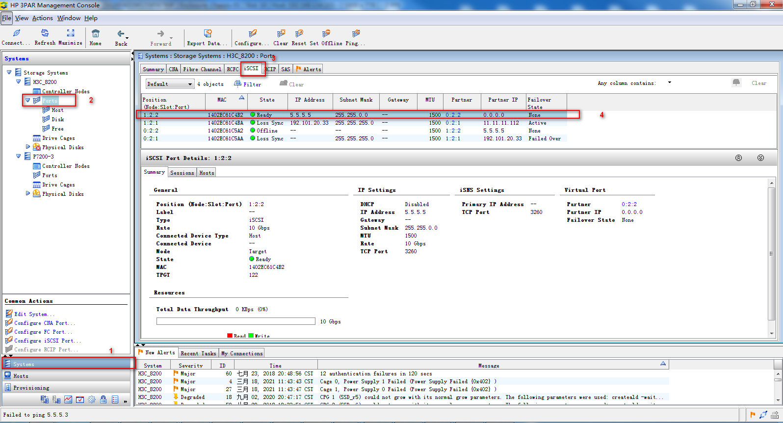
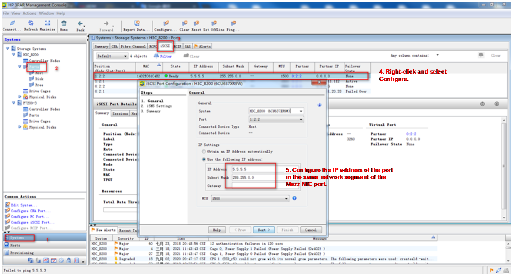
1. Obtain the iSCSI port information, as shown in Figure 14. On the 3PAR Management Console, log in and connect to 192.168.8.156 using the username 3Param and password 3pardata. You can obtain the corresponding NIC port information on the iSCSI tab.
Figure 14 Obtaining the iSCSI port information
2. Change the IP address of the iSCSI network to 5.5.5.5/16, as shown in Figure 15.
Figure 15 Setting the IP address
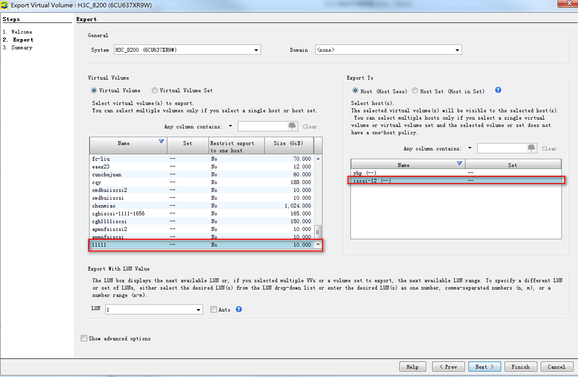
3. Create a persistent volume and associate the iSCSI port, as shown in Figure 16. Complete the configuration as follows:
a. Create a host. Select Hosts > Create Host, and set the host name to 1111.
b. Create a persistent volume. Select Provisioning > Create Virtual Volume, and create a persistent volume iSCSI-12.
c. Associate the host with the volume. Select Hosts > Export Volume, and associate Host 1111 with iSCSI-12.
d. Associate the host with the device. Select Hosts > Edit Host, and associate Host 1111 with the server.
Figure 16 Associating the persistent volume with the iSCSI port
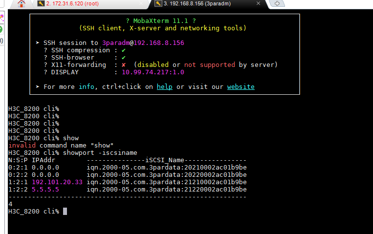
4. Obtain the iqn, as shown in Figure 17:
a. Use the SSH software to log in to 192.168.8.156 by entering the username 3paradm and password 3pardata.
b. Execute the Showport -iSCSIname command.
Figure 17 Associating the persistent volume with the iSCSI port
Creating iSCSI-1
1. Select Enclosure Profile Management > Profile Template Management > Network Profile Template > Net Template > iSCSI Network Template > Create.
2. Configure the following parameters according to the configuration analysis:
a. Set Network Name to iSCSI-1.
b. In the Add Port area, select the ICM in slot 1, and select the external port, Port 10 (XGE1/1/1), as the uplink port of the iSCSI-1 network profile.
c. Click OK.
Creating the network profile Profile-1
1. Select Enclosure Profile Management > Profile Template Management > Network Profile Template > Profile Template > Create.
2. Enter the profile template name Profile-1, and select the blade server model B5700 G3.
3. Configure the vNET-1 network of Mezz 1.
a. On the Mezz 1 tab, set Slot No. to 1.
b. Set Mezz Model to NIC-ETH521i-Mb-4*10G.
c. In the Port 3 area, set Network Name to Multiple networks.
d. In the dialog box displayed, select vNET-1, and click Add to add it to the selected network list.
e. Set Server VLAN ID to 200.
f. Click OK.
4. Configure the iSCSI-1 network of Mezz 1.
a. In the Port 1 area, set Network Name to Select an iSCSI network.
b. In the dialog box displayed, select iSCSI-1.
c. Configure iSCSI parameters.
d. Click OK.
5. Configure the vNET-2 and vNET-3 networks of Mezz 2.
a. Click ![]() to add the Mezz 2 tab.
to add the Mezz 2 tab.
b. On the Mezz 2 tab, set Slot No. to 2.
c. Set Mezz Model to NIC-ETH682i-Mb-2*25G.
d. In the Port 2 area, set Network Name to Multiple networks.
e. In the dialog box displayed, select vNET-2 and vNET-3 and add them to the selected network list.
f. Click OK.
6. Configure the SAN-1 network of Mezz 2.
a. In the Port 1 area, set Network Name to Select a SAN network.
b. In the dialog box displayed, select SAN-1.
c. Click OK.
7. Configure the SAN-2 network of Mezz 3.
a. Click ![]() to add the Mezz 3 tab.
to add the Mezz 3 tab.
b. On the Mezz 2 tab, set Slot No. to 3.
c. Set Mezz Model to NIC-FC730i-Mb-2*32G.
d. In the Port 1 area, set Network Name to Select a SAN network.
e. In the dialog box displayed, select SAN-2.
f. Click OK.
8. Click OK
Creating and applying a blade server profile
1. Select Enclosure Profile Management > Profile Template Management > Blade Server Profile Template > Create.
2. Configure the following parameters of the blade server profile template according to the configuration analysis:
a. Set Name to BladeProfile-1.
b. Set Blade Serer Model to B5700 G3.
c. In the Network Profile Configuration area, select Profile-1 from the Select Network Profile drop-down list box.
d. Click OK.
3. Select the created blade server profile BladeProfile-1, and click Apply.
4. Set Associated Slot to 1, and click Save.
Configuring the TOR switch
Creating a VLAN and allowing the traffic of VLAN 100 to pass through ports XGE1/0/1 and XGE1/0/2
# Create VLAN 100.
[H3C] vlan100
[H3C-vlan100]quit
# Enable the traffic of VLAN 100 to pass through the port.
[H3C] interface Ten-GigabitEthernet 1/0/1
[H3C-Ten-GigabitEthernet1/0/1]
[H3C-Ten-GigabitEthernet1/0/1] port link-type trunk
[H3C-Ten-GigabitEthernet1/0/1] port trunk permit vlan 100
[H3C-Ten-GigabitEthernet1/0/1] display this
#
interface Ten-GigabitEthernet 1/0/1
port link-type trunk
port trunk permit vlan 1 100
#
Return
[H3C-Ten-GigabitEthernet1/0/1]
[H3C-Ten-GigabitEthernet1/0/1] quit
[H3C]
[H3C] interface Ten-GigabitEthernet 1/0/2
[H3C-Ten-GigabitEthernet1/0/2]
[H3C-Ten-GigabitEthernet1/0/2] port link-type trunk
[H3C-Ten-GigabitEthernet1/0/2] port trunk permit vlan 100
[H3C-Ten-GigabitEthernet1/0/2] display this
#
interface Ten-GigabitEthernet 1/0/2
port link-type trunk
port trunk permit vlan 1 100
#
return
[H3C-Ten-GigabitEthernet1/0/2]
[H3C-Ten-GigabitEthernet1/0/2]
# Create a VLAN port and set the IP address of the port to 192.168.20.2/24.
[H3C] interface vlan 100
[H3C-Vlan-interface100] ip address 192.168.20.2 255.255.255.0
[H3C-Vlan-interface100] quit
# Check the VLAN interface status and confirm that the interface is UP.
[H3C-Vlan-interface2]display interface vlan 100 brief
Brief information on interfaces in route mode:
Link: ADM - administratively down; Stby - standby
Protocol: (s) - spoofing
Interface Link Protocol Primary IP Description
Vlan100 UP UP 192.168.20.2
# Save the configuration.
[H3C] save
The current configuration will be written to the device. Are you sure? [Y/N]:y
Please input the file name(*.cfg)[flash:/startup.cfg]
(To leave the existing filename unchanged, press the enter key):
Creating an aggregation port and allowing the traffic of VLAN 400 and VLAN 500 to pass through
# Create VLAN 400 and VLAN 500.
[H3C] vlan400
[H3C-vlan400]quit
[H3C] vlan500
[H3C-vlan500]quit
# Create a L2 aggregation port, add the physical port to the aggregation group, and allow the traffic of VLAN 400 and VLAN 500 to pass through.
[H3C] interface Bridge-Aggregation 30
[H3C-Bridge-Aggregation30]
[H3C-Bridge-Aggregation20]link-aggregation mode dynamic
[H3C] interface Twenty-FiveGigE 1/0/10
[H3C-Twenty-FiveGigE1/0/10] port link-aggregation group 30
[H3C-Twenty-FiveGigE1/0/10] quit
[H3C] interface Twenty-FiveGigE1/0/11
[H3C-Twenty-FiveGigE1/0/11] port link-aggregation group 30
[H3C-Twenty-FiveGigE1/0/11] quit
# You can view the information about the aggregation port and confirm that the aggregation port has been created.
[H3C] display link-aggregation verbose Bridge-Aggregation 30
Loadsharing Type: Shar -- Loadsharing, NonS -- Non-Loadsharing
port Status: S -- Selected, U -- Unselected, I -- Individual
port: A -- Auto port, M -- Management port, R -- Reference port
Flags: A -- LACP_Activity, B -- LACP_Timeout, C -- Aggregation,
D -- Synchronization, E -- Collecting, F -- Distributing,
G -- Defaulted, H -- Expired
Aggregate Interface: Bridge-Aggregation30
Aggregation Mode: dynamic
Loadsharing Type: Shar
Management VLANs: None
port Status Priority Oper-Key
WGE1/0/10 S 32768 1
WGE1/0/11 S 32768 1
# Create two VLAN interfaces, and set the IP addresses of these interfaces to 192.168.40.2/24 and 192.168.50.2/24.
[H3C] interface vlan 400
[H3C-Vlan-interface400] ip address 192.168.40.2 255.255.255.0
[H3C-Vlan-interface400] quit
[H3C] interface vlan 500
[H3C-Vlan-interface500] ip address 192.168.50.2 255.255.255.0
[H3C-Vlan-interface500] quit
# Check the VLAN interface status and confirm that the interface is UP.
[H3C] interface vlan 400
[H3C-Vlan-interface400]display interface vlan 400 brief
Brief information on interfaces in route mode:
Link: ADM - administratively down; Stby - standby
Protocol: (s) - spoofing
Interface Link Protocol Primary IP Description
Vlan400 UP UP 192.168.40.2
[H3C] interface vlan 500
[H3C-Vlan-interface500]display interface vlan 500 brief
Brief information on interfaces in route mode:
Link: ADM - administratively down; Stby - standby
Protocol: (s) - spoofing
Interface Link Protocol Primary IP Description
Vlan500 UP UP 192.168.50.2
# Save the configuration.
[H3C] save
The current configuration will be written to the device. Are you sure? [Y/N]:y
Please input the file name(*.cfg)[flash:/startup.cfg]
(To leave the existing filename unchanged, press the enter key):
Configuring each service IP address
Query the interface connection between Mezz NICs and ICMs
Please use the H3C networking query tool on the official website to view the port connection relation between mezzanine cards and interconnect modules.
Querying the MAC address of the Mezz NIC
Log in to the OM Web page, select Blade Server Management, click the target blade server, and click Port Mapping to view the MAC address of the port on the Mezz NIC.
Querying the port correspondence between the network adapter and the mezzanine card under the OS
1. Execute the ifconfig command in the Linux operating system to view the MAC addresses of all NICs.
2. Obtain the relationship between the NIC in the OS and the Mezz NIC port based on the MAC address queried in the previous step.
Configuring each service IP address
1. As shown in Figure 18, add Port 1, Port 2, and Port 4 to VLAN 200, VLAN 400, VLAN 10, and VLAN 500, and configure the IP addresses 192.168.20.1, 192.168.40.1, and 192.168.50.1, respectively.
Figure 18 Configuring the IP address of each port

Verifying the configuration
1. As shown in Figure 5, the gateway address of the R&D Department can be successfully pinged on Port 1.
Figure 19 Checking whether the network is normal on Port 1
2. As shown in Figure 7 and Figure 8, the gateway address of the Marketing Department can be successfully pinged on Port 2 and Port 4.
Figure 20 Checking whether the network is normal on Port 2

Figure 21 Checking whether the network is normal on Port 4

3. Replace the original blade server with a blade server that has the same hardware configuration and software configuration.
4. As shown in Figure 22, the gateway address of the R&D Department can still be successfully pinged on Port 1.
Figure 22 Checking whether the network is normal on Port 1

5. As shown in Figure 23, the gateway address of the Marketing Department can still be successfully pinged on Port 2 and Port 4.
Figure 23 Checking whether the network is normal on Port 2

Figure 24 Checking whether the network is normal on Port 4
6. Log in to the system on Blade 1 and view the persistent volume. You can see that there is a new disk device (3PARdata). The loaded remote storage can be recognized through Link 2, Link 3, and Link 5.
xample: Configuring a VC profile on the OM Web page in the QinQ scenario – 1.02.xx or later
Network requirements
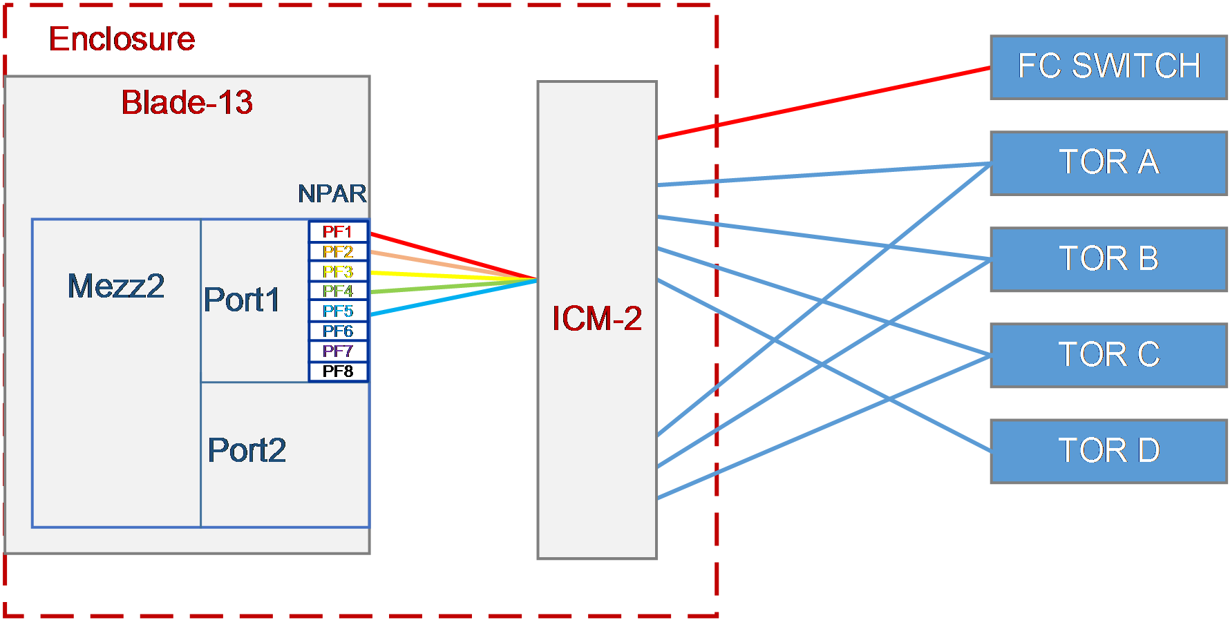
As shown in Figure 25, a blade server and an ICM are installed in the H3C B16000 blade server chassis.
· The blade server is installed in slot 13. The Mezz NIC is installed in the slot of Mezz 2 at the rear of the blade server.
· The ICM is installed in the slot of ICM 2.
· The ICM is connected to four Ethernet switches and one FC switch.
¡ Ten-GigabitEthernet1/1/9 and Ten-GigabitEthernet1/1/13 are connected to XGE1/0/9 and XGE1/0/13 of the TOR switch.
¡ Ten-GigabitEthernet1/1/10 and Ten-GigabitEthernet1/1/14 are connected to XGE1/0/10 and XGE1/0/14 of the TOR switch.
¡ Ten-GigabitEthernet1/1/11 and Ten-GigabitEthernet1/1/15 are connected to XGE1/0/11 and XGE1/0/15 of the TOR switch.
¡ Ten-GigabitEthernet1/1/12 is connected to XGE1/0/12 of the TOR switch.
¡ Ten-GigabitEthernet1/1/13 is connected to Port 13 of the FC switch.
In this example, the blade server used is H3C UniServer B5700 G3, the Mezz NIC used is NIC-ETH682i-Mb-2*25G (ETH682i for short), and the ICM used is H3C UniServer BX1020EF
A VC profile needs to be configured so that different departments of the company can access different services through one port of the Mezz NIC on the blade server, and departments are isolated from each other. The specific requirements are as follows:
· Configure the QinQ NPAR function for the Mezz NIC to divide Port 1 of ETH682i into eight PFs.
· Connect PF 1 of Mezz NIC to the storage network to provide storage resources for the blade server.
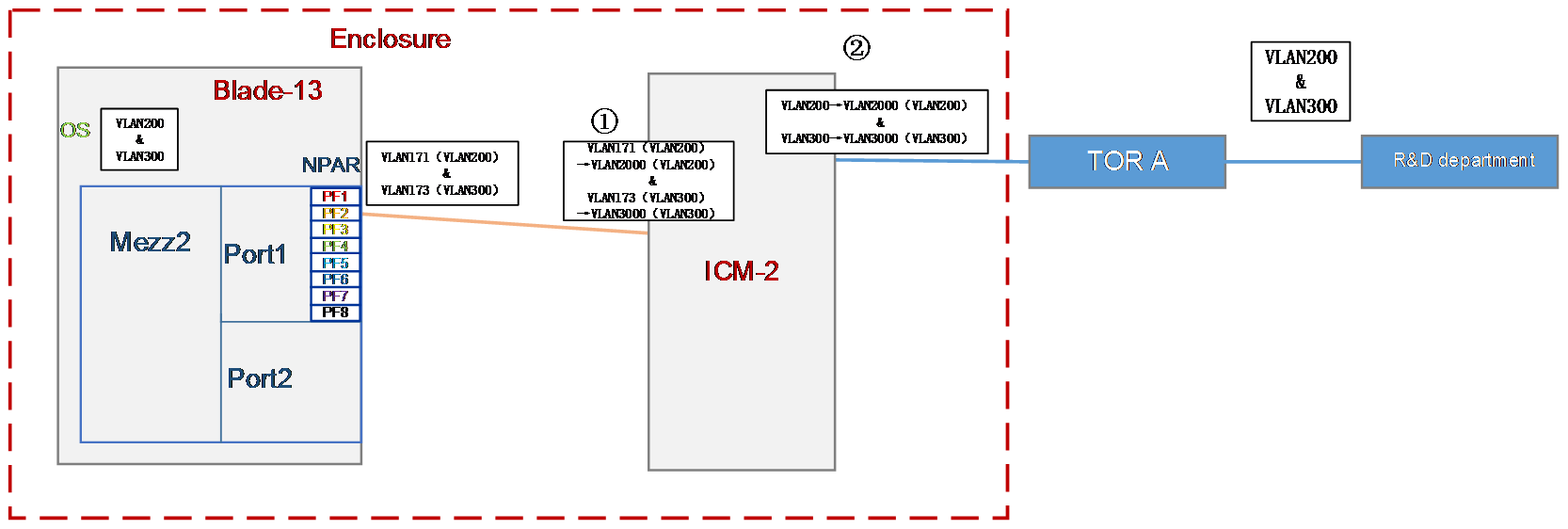
· Allocate the R&D Department to VLAN 200 and VLAN 300, and the gateway addresses are 192.109.120.2 and 192.109.130.2. This department needs to access the service resources of VLAN 200 and VLAN 300, and the service IP addresses are 192.109.120.1 and 192.109.130.1. It connects to the corresponding network through PF 2 of Mezz NIC.
· Allocate the Quality Department to VLAN 200 and VLAN 300, and the gateway addresses are 192.109.120.2 and 192.109.130.2. This department needs to access the service resources of VLAN 200 and VLAN 300, and the service IP addresses are 192.109.120.1 and 192.109.130.1. It connects to the corresponding network through PF 3 of Mezz NIC.
· The Marketing Department requires that services can pass through any network. Therefore, allocate the Marketing Department to VLAN 200 and VLAN 300, and the gateway addresses are 192.109.120.2 and 192.109.130.2. This department needs to access the service resources of VLAN 200 and VLAN 300, and the service IP addresses are 192.109.120.1 and 192.109.130.1. It connects to the corresponding network through PF 4 of Mezz NIC.
· No VLAN is configured for the O&M Department. The gateway address is 192.109.10.2, and the service IP address is 192.109.10.1. This department connects to the corresponding network through PF 5 of Mezz NIC.
· Isolate networks of these departments from each other.
Analysis
· To ensure that these departments can communicate with each other, the packets with the VLAN 200 and VLAN 300 tags on ports PF 2, PF 3 and PF 4 of the Mezz NIC in Blade 13 must be sent to the ports of the TOR switch through the external ports of ICM 2.
· To ensure isolation of services between different departments, configure the QinQ VLAN function on the NIC, and ensure that the QinQ VLAN of each port of the NIC with the same Mezz NIC slot in the blade server is different.
· To ensure the isolation of services between different departments, use different QinQ VLAN values for different networks on the same ICM.
Software versions used
Procedures
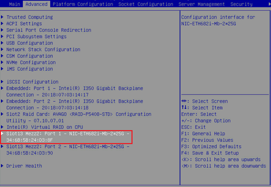
Configuring the NPAR function for the NIC in BIOS
1. As shown in Figure 26, select Port 1 of the ETH682i NIC on the Advanced tab of BIOS, and enter its configuration page.
Figure 26 NIC configuration page in BIOS
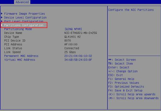
2. As shown in Figure 27, set Partitioning Mode to QINQ NPAR.
Figure 27 Configuring the QINQ NPAR mode

3. Configure the QinQ VLAN that a single NPAR port allows to pass through.
a. As shown in Figure 28, select Partitions Configuration.
Figure 28 Selecting Partitions Configuration
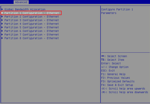
b. As shown in the figure below, select Partition 1 Configuration - Ethernet.
Figure 29 Selecting Partition 1 Configuration - Ethernet
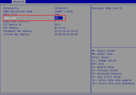
c. As shown in the figure below, configure QinQ VLAN.
Figure 30 Configuring the QinQ VLAN
4. Repeat the above steps to configure the QinQ VLANs of all partition ports.
5. Save the configuration and restart the server.
Configuring the FCoE function for the Mezz NIC in the operating system
|
|
NOTE: · In this example, Red Hat 7.5 is installed on the blade server and used as an example in the following steps. |
1. Configure the FCoE function of ens5f0 and ens5f2 ports:
a. Under the /etc/fcoe directory, execute the cp cfg-ethX cfg-ethM command to copy and create the FCoE port configuration file. Where, cfg-ethM indicates the port name for FCoE connection. In this example, the names are cfg-ens5f0 and cfg-ens5f2. The following contents use cfg-ens5f0 as an example to describe the configuration steps.
[root@localhost]# cd /etc/fcoe/
[root@localhost fcoe]# ls
cfg-ethx
[root@localhost fcoe]# cp cfg-ethx cfg-ens5f0
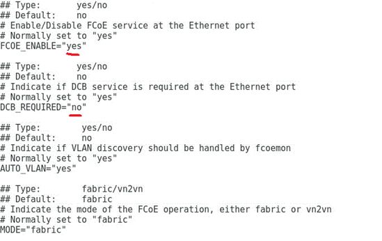
b. Execute the vi cfg-ethM command, edit and save the configuration file of the FCoE port, and ensure that FCoE_ENABLE is set to yes and DCB_REQUIRED is set to no, as shown in Figure 31.
[root@localhost fcoe]# vi cfg-ens5f0
Figure 31 Editing the FCoE port configuration file
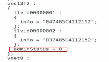
c. Execute the lldptool set-lldp -i ethM adminStatus=disabled command to set the LLDP admin status of the port to disabled. Then, check the configuration value of adminStatus of ethM in the /var/lib/lldpad/lldpad.conf configuration file. If it is zero, the command is executed successfully. If it is not, manually add a line "adminStatus = 0" to the "ethM" entry under "lldp" in the configuration file, as shown in Figure 32.
[root@localhost fcoe]# lldptool set-lldp –i ens5f0 adminStatus=disabled
Figure 32 Disabling the LLDP admin status
d. Execute the service fcoe restart and service lldpad restart commands to restart the FCoE and LLDP services.
[root@localhost fcoe]# service lldpad restart
[root@localhost fcoe]# service fcoe restart
e. Execute the chkconfig fcoe on and chkconfig lldpad on commands to automatically load the FCoE and LLDP services during the boot phase.
[root@localhost fcoe]# chkconfig fcoe on
[root@localhost fcoe]# chkconfig lldpad on
Configuring the ICM in the shared uplink port network
Configuration in this section is expected to realize the following translation function:
1. Implement 2:2 VLAN mapping on the internal port 1/0/26 of the ICM to translate the outer tags VLAN 171 and VLAN 173 in the received packets into VLAN 2000 and VLAN 2001.
2. Translate the outer tags VLAN 200 and VLAN300 in the packets received by the external ports 1/1/9 and 1/1/10 of the ICM into VLAN 2000 and VLAN 2001.
Figure 33 VLAN mapping process
Configuring the VLANs and VLAN mapping for the internal port of the ICM
# Access the internal port of the ICM.
<H3C> system-view
[H3C]int Ten-GigabitEthernet 1/0/26
# Set the port to the trunk mode.
[H3C-Ten-GigabitEthernet1/0/26]port link-type trunk
[H3C-Ten-GigabitEthernet1/0/26]undo port trunk permit vlan 1
# Enable the port to allow the QinQ VLANs 171 and 173 of the NIC and reserved VLANs 2000 and 2001 of the ICM external ports.
[H3C-Ten-GigabitEthernet1/0/26]port trunk permit vlan 171 173 2000 2001
# Configure VLAN mapping. Implement 2:2 VLAN mapping on the internal port to translate the outer tags VLAN 171 and VLAN 173 in the received packets into VLAN 2000 and VLAN 2001, respectively, and keep the inner VLAN tags unchanged.
[H3C-Ten-GigabitEthernet1/0/26]vlan mapping tunnel 171 200 translated-vlan 2000 200
[H3C-Ten-GigabitEthernet1/0/26]vlan mapping tunnel 171 300 translated-vlan 2000 300
[H3C-Ten-GigabitEthernet1/0/26]vlan mapping tunnel 173 200 translated-vlan 2001 200
[H3C-Ten-GigabitEthernet1/0/26]vlan mapping tunnel 173 300 translated-vlan 2001 300
Configuring the VLANs and VLAN mapping for the external port of the ICM
# Configure the external port 1/1/9 of the ICM.
<H3C> system-view
[H3C]interface Ten-GigabitEthernet 1/1/9
[H3C-Ten-GigabitEthernet1/1/9]port link-type hybrid
[H3C-Ten-GigabitEthernet1/1/9]undo port hybrid vlan 1
# Untag the VLAN 2000 reserved for the external port 1/1/9 of the ICM.
[H3C-Ten-GigabitEthernet1/1/9]port hybrid vlan 2000 untagged
# Configure VLAN mapping. Implement 1:2 VLAN mapping on the external port: The VLAN tags are 200 and 300 before mapping, and the outer VLAN tag added is 2000 after mapping.
[H3C-Ten-GigabitEthernet1/1/9]vlan mapping nest single 200 300 nested-vlan 2000
# Configure the external port 1/1/10 of the ICM.
[H3C-Ten-GigabitEthernet1/1/9]interface Ten-GigabitEthernet 1/1/10
[H3C-Ten-GigabitEthernet1/1/10]port link-type hybrid
[H3C-Ten-GigabitEthernet1/1/10]undo port hybrid vlan 1
# Untag the VLAN 2001 reserved for the external port 1/1/10 of the ICM.
[H3C-Ten-GigabitEthernet1/1/10]port hybrid vlan 2001 untagged
# Configure VLAN mapping. Implement 1:2 VLAN mapping on the external port: The VLAN tags are 200 and 300 before mapping, and the outer VLAN tag added is 2001 after mapping.
[H3C-Ten-GigabitEthernet1/1/10]vlan mapping nest single 200 300 nested-vlan 2001
Configuring the ICM in the tunnel network
Configuration in this section is expected to realize the following translation function:
· Implement 1:1 VLAN mapping on the internal port 1/0/26 of the ICM to translate the tag VLAN 175 in the received packets into VLAN 2002.
· Enable the external port 1/1/11 of the ICM to receive packets with the tag VLAN 2002.
Figure 34 VLAN mapping process
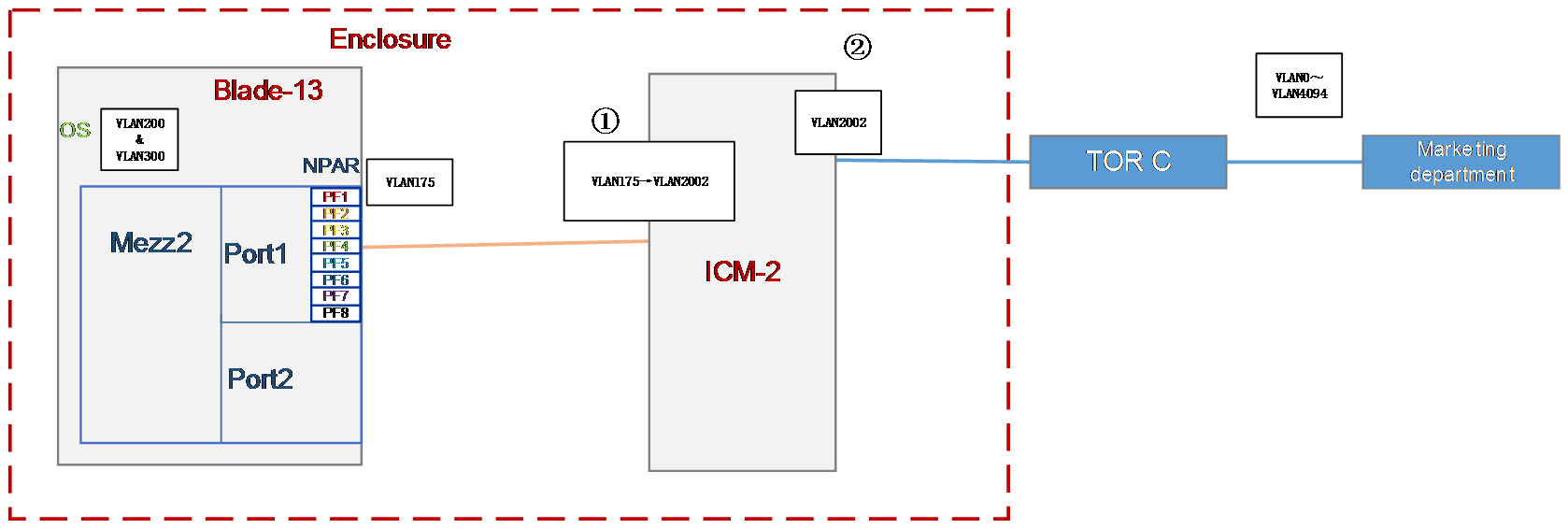
Configuring the VLANs and VLAN mapping for the internal port of the ICM
<H3C> system-view
[H3C]int Ten-GigabitEthernet 1/0/26
# Set the port to the trunk mode.
[H3C-Ten-GigabitEthernet1/0/26]port link-type trunk
[H3C-Ten-GigabitEthernet1/0/26]undo port trunk permit vlan 1
# Enable the port to allow the QinQ VLAN 175 of the NIC and reserved VLAN 2002 of the ICM external port.
[H3C-Ten-GigabitEthernet1/0/26]port trunk permit vlan 175 2002
# Configure VLAN mapping. Implement 1:1 VLAN mapping on the internal port: The VLAN tag is 175 before mapping and 2002 after mapping.
[H3C-Ten-GigabitEthernet1/0/26]vlan mapping 175 translated-vlan 2002
Configuring the VLANs and VLAN mapping for the external port of the ICM
# Configure the external port of the ICM.
<H3C> system-view
[H3C]interface Ten-GigabitEthernet 1/1/11
[H3C-Ten-GigabitEthernet1/1/11]port link-type hybrid
[H3C-Ten-GigabitEthernet1/1/11]undo port hybrid vlan 1
# Untag the VLAN 2002 reserved for the external port of the ICM.
[H3C-Ten-GigabitEthernet1/1/11]port hybrid vlan 2002 untagged
# Configure the PVID and QinQ, and add the PVID tag to the packets received by the external port.
[H3C-Ten-GigabitEthernet1/1/11]port hybrid pvid vlan 2002
[H3C-Ten-GigabitEthernet1/1/11]qinq enable
Configuring the ICM in a common network
Configuration in this section is expected to realize the following translation function:
· Implement 2:1 VLAN mapping on the internal port 1/0/26 of the ICM to translate the two VLAN tags (the inner one is 4094 and the outer one is 2003) in the received packets into the VLAN tag 177.
· Implement 0:2 VLAN mapping on the external port 1/1/11 of the ICM to add the two VLAN tags (the inner one is 4094 and the outer one is 2003) to each untagged packet.
Figure 35 VLAN mapping process
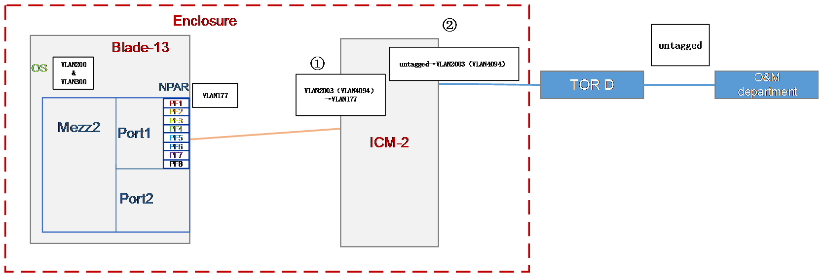
Configuring the VLANs and VLAN mapping for the internal port of the ICM
# Set the port to the trunk mode.
<H3C> system-view
[H3C]int Ten-GigabitEthernet 1/0/26
[H3C-Ten-GigabitEthernet1/0/26]port link-type trunk
[H3C-Ten-GigabitEthernet1/0/26]undo port trunk permit vlan 1
# Enable the port to allow the QinQ VLAN 177 of the NIC and reserved VLAN 2003 of the ICM external port.
[H3C-Ten-GigabitEthernet1/0/26]port trunk permit vlan 177 2003
# Configure VLAN mapping. Implement 2:1 VLAN mapping on the internal port to translate the two VLAN tags (the inner one is 4094 and the outer one is 2003) in the received packets into the VLAN tag 177.
[H3C-Ten-GigabitEthernet1/0/26]vlan mapping egress outer-vlan 2003 inner-vlan 4094 translated-vlan 177
Configuring the VLANs and VLAN mapping for the external port of the ICM
# Configure the external port of the ICM.
<H3C> system-view
[H3C]interface Ten-GigabitEthernet 1/1/12
[H3C-Ten-GigabitEthernet1/1/12]port link-type hybrid
[H3C-Ten-GigabitEthernet1/1/12]undo port hybrid vlan 1
# Untag the VLAN 2003 reserved for the external port of the ICM.
[H3C-Ten-GigabitEthernet1/1/12]port hybrid vlan 2003 untagged
# Configure VLAN mapping. Implement 0:2 VLAN mapping on the external port of the ICM to add the two VLAN tags (the inner one is 4094 and the outer one is 2003) to each untagged packet.
[H3C-Ten-GigabitEthernet1/1/12] vlan mapping untagged nested-outer-vlan 2003 nested-inner-vlan 4094
Configuring the FCoE network (NPV mode)
Interconnecting interconnect modules and mezzanine cards
1. Configuring FCoE-related settings and ports
<H3C> system-view
# Configure the FCoE mode of the switch to NPV.
[H3C] fcoe-mode npv
# Create a VSAN. In this example, create VSAN 10 and configure load balancing.
[H3C] vsan 10
[H3C-vsan10] npv auto-load-balance enable
[H3C-vsan4] quit
# Create the VLAN to map VSAN. In this example, create VLAN 4, enable the FCoE function in VLAN 10, and map the VLAN to VSAN 10.
[H3C] vlan 10
[H3C-vlan10] fcoe enable vsan 10
[H3C-vlan10] quit
# Create VFC ports and bind them with internal ports XGE1/0/26.
[H3C] interface vfc 1
[H3C-Vfc1] bind interface Ten-GigabitEthernet1/0/26
[H3C-Vfc1] port trunk vsan 1
[H3C-Vfc1] quit
# Set the internal port to the trunk mode and allow VLAN 10 and VLAN 491 (VLAN 491 is the QinQ VLAN under the PF of the Mezz NIC configured in the BIOS).
[H3C] interface Ten-GigabitEthernet1/0/26
[H3C-Ten-GigabitEthernet1/0/26] port link-type trunk
[H3C-Ten-GigabitEthernet1/0/26] port trunk permit vlan 10 491
# Configure VLAN mapping.
[H3C-Ten-GigabitEthernet1/0/26] vlan mapping uni single 491 translated-vlan 10
[H3C-Ten-GigabitEthernet1/0/26] quit
2. Deploying DCBX
# Enable LLDP function globally.
[H3C] lldp global enable
# Create a Layer 2 ACL named DCBX and create rules for it to match FCoE packets (protocol number 0x8906) and FIP packets (protocol number 0x8914).
[H3C] acl mac name DCBX
[H3C-acl-mac-DCBX] rule 0 permit type 8906 ffff
[H3C-acl-mac-DCBX] rule 5 permit type 8914 ffff
[H3C-acl-mac-DCBX] quit
# Define a class named DCBX, the relation between the rules under it is OR, and define it to match the ACL named DCBX.
[H3C] traffic classifier DCBX operator or
[H3C-classifier-DCBX] if-match acl mac name DCBX
[H3C-classifier-DCBX] quit
# Define a stream behavior named DCBX and set the priority of the marked packets 802.1p to 3.
[H3C] traffic behavior DCBX
[H3C-behavior-DCBX] remark dot1p 3
[H3C-behavior-DCBX] quit
# Define a QoS policy named DCBX, specify the DCBX-like stream behavior as DCBX, and specify the policy as DCBX mode.
[H3C] qos policy DCBX
[H3C-qospolicy-DCBX] classifier DCBX behavior DCBX mode dcbx
[H3C-qospolicy-DCBX] quit
# Enable the LLDP function on the aggregate interfaces, and configure the bound physical interfaces to allow the interface to send LLDP packets with DCBSX TLV fields.
[H3C] interface Ten-GigabitEthernet 1/0/26
[H3C-Ten-GigabitEthernet1/0/26] lldp tlv-enable dot1-tlv dcbx
[H3C-Ten-GigabitEthernet1/0/26] qos apply policy DCBX outbound
[H3C-Ten-GigabitEthernet1/0/26] quit
3. Deploying PFC
# Configure the function to enable PFC through automatic negotiation with the server on the physical ports, enable the PFC function for 802.1p with priority set to 3, and configure to trust packets with the 802.1p priority.
[H3C] interface Ten-GigabitEthernet 1/0/26
[H3C-Ten-GigabitEthernet1/0/26] priority-flow-control auto
[H3C-Ten-GigabitEthernet1/0/26] priority-flow-control no-drop dot1p 3
[H3C-Ten-GigabitEthernet1/0/26] qos trust dot1p
[H3C-Ten-GigabitEthernet1/0/26] quit
4. Deploying ETS
# Configure the mapping from 802.1p priority to local priority, map 802.1p priority 3 to local priority 1, and map other 802.1p priorities to local priority 0.
[H3C] qos map-table dot1p-lp
[H3C-maptbl-dot1p-lp] import 3 export 1
[H3C-maptbl-dot1p-lp] import 0 export 0
[H3C-maptbl-dot1p-lp] import 1 export 0
[H3C-maptbl-dot1p-lp] import 2 export 0
[H3C-maptbl-dot1p-lp] import 4 export 0
[H3C-maptbl-dot1p-lp] import 5 export 0
[H3C-maptbl-dot1p-lp] import 6 export 0
[H3C-maptbl-dot1p-lp] import 7 export 0
[H3C-maptbl-dot1p-lp] quit
# Configure other queues to SP scheduling on the physical interface bound to the aggregate interface.
[H3C] interface Ten-GigabitEthernet 1/0/26
[H3C-Ten-GigabitEthernet1/0/26] qos wrr af2 group sp
[H3C-Ten-GigabitEthernet1/0/26] qos wrr af3 group sp
[H3C-Ten-GigabitEthernet1/0/26] qos wrr af4 group sp
[H3C-Ten-GigabitEthernet1/0/26] qos wrr ef group sp
[H3C-Ten-GigabitEthernet1/0/26] qos wrr cs6 group sp
[H3C-Ten-GigabitEthernet1/0/26] qos wrr cs7 group sp
[H3C-Ten-GigabitEthernet1/0/26] quit
5. Verifying that the FCoE protocol has been negotiated
# Execute the fcoeadm -i command under the OS to query the information about the ports with FCoE configured and confirm that the protocol has been negotiated, as shown in Figure 36.
Figure 36 Querying the information about ports with FCoE configured
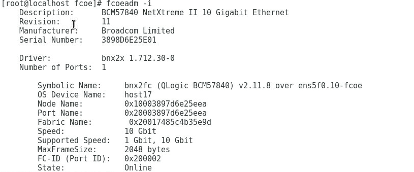
Interconnecting interconnect modules and FC switches
# Switch the external port XGE1/1/1 to an FC port.
[H3C] interface Ten-GigabitEthernet 1/1/1
[H3C-Ten-GigabitEthernet1/1/1] port-type fc
The interface Ten-GigabitEthernet1/1/1, Ten-GigabitEthernet1/1/2, Ten-GigabitEth
ernet1/1/3, and Ten-GigabitEthernet1/1/4 will be deleted. Continue? [Y/N]:y
%Apr 3 18:49:23:050 2019 H3C OPTMOD/4/MODULE_IN: Fc1/1/1: The transceiver is 16
G_FC_SW_SFP.
# Enable the port FC1/1/1 to allow VSAN 4.
[H3C-Fc1/1/1] port access vsan 4
[H3C-Fc1/1/1] fc mode np
[H3C-Fc1/1/1] qos trust dot1p
# Save the configuration.
[H3C] save
The current configuration will be written to the device. Are you sure? [Y/N]:y
Please input the file name(*.cfg)[flash:/startup.cfg]
(To leave the existing filename unchanged, press the enter key):
# Check the information about the VFC port on the interconnect module, and confirm that the VFC port is UP.
[H3C]display interface vfc 1 brief
Brief information on VFC interface(s):
Admin Mode: E - e port; F - f port; NP - n port proxy
Oper Mode: TE - trunking e port; TF - trunking f port;
TNP - trunking n port proxy
Interface Admin Admin Oper Status Bind
Mode Trunk Mode Interface
Mode
Vfc1 F on -- UP XGE1/0/26
Querying the WWN number of the mezzanine card
Execute the display npv login command on the aggregation interconnect module to view the registration information about the node device connected to the downlink port of the aggregation interconnect module and the mapped uplink port.
<H3C> display npv login
Server External
Interface VSAN FCID Node WWN Port WWN Interface
Vfc1 1 0x021101 20:00:f4:e9:D4:53:f1:c5 21:00:f4:e9:D4:53:f1:c5 Fc1/1/1
Configuring the FCoE network (FCF mode)
Interconnecting interconnect modules and mezzanine cards
1. Configuring FCoE-related settings and ports
<H3C> system-view
# Configure the FCoE mode of the switch to FCF.
[H3C] fcoe-mode fcf
# Create a VSAN. In this example, create VSAN 10 and allow members in the default zone to access each other.
[H3C] vsan 10
[H3C-vsan10] zone default-zone permit
[H3C-vsan10] quit
# Create the VLAN to map VSAN. In this example, create VLAN 10, enable the FCoE function in VLAN 10, and map the VLAN to VSAN 10.
[H3C] vlan 10
[H3C-vlan10] fcoe enable vsan 10
[H3C-vlan10] quit
# Create VFC ports and bind them with internal ports XGE1/0/26.
[H3C] interface vfc 1
[H3C-Vfc1] bind interface Ten-GigabitEthernet1/0/26
[H3C-Vfc1] port trunk vsan 1
[H3C-Vfc1] quit
# Set the internal port to trunk mode, and allow VLAN 10 and VLAN 491.
[H3C] interface Ten-GigabitEthernet1/0/26
[H3C-Ten-GigabitEthernet1/0/26] port link-type trunk
[H3C-Ten-GigabitEthernet1/0/26] port trunk permit vlan 10 491
# Configure VLAN mapping.
[H3C-Ten-GigabitEthernet1/0/26] vlan mapping uni single 491 translated-vlan 10
[H3C-Ten-GigabitEthernet1/0/26] quit
2. Deploying DCBX
# Enable LLDP function globally.
[H3C] lldp global enable
# Create a Layer 2 ACL named DCBX and create rules for it to match FCoE packets (protocol number 0x8906) and FIP packets (protocol number 0x8914).
[H3C] acl mac name DCBX
[H3C-acl-mac-DCBX] rule 0 permit type 8906 ffff
[H3C-acl-mac-DCBX] rule 5 permit type 8914 ffff
[H3C-acl-mac-DCBX] quit
# Define a class named DCBX, the relation between the rules under it is OR, and define it to match the ACL named DCBX.
[H3C] traffic classifier DCBX operator or
[H3C-classifier-DCBX] if-match acl mac name DCBX
[H3C-classifier-DCBX] quit
# Define a stream behavior named DCBX and set the priority of the marked packets 802.1p to 3.
[H3C] traffic behavior DCBX
[H3C-behavior-DCBX] remark dot1p 3
[H3C-behavior-DCBX] quit
# Define a QoS policy named DCBX, specify the DCBX-like stream behavior as DCBX, and specify the policy as DCBX mode.
[H3C] qos policy DCBX
[H3C-qospolicy-DCBX] classifier DCBX behavior DCBX mode dcbx
[H3C-qospolicy-DCBX] quit
# Enable the LLDP function on the aggregate interfaces, and configure the bound physical interfaces to allow the interface to send LLDP packets with DCBSX TLV fields.
[H3C] interface Ten-GigabitEthernet 1/0/26
[H3C-Ten-GigabitEthernet1/0/26] lldp tlv-enable dot1-tlv dcbx
[H3C-Ten-GigabitEthernet1/0/26] qos apply policy DCBX outbound
[H3C-Ten-GigabitEthernet1/0/26] quit
3. Deploying PFC
# Configure the function to enable PFC through automatic negotiation with the server on the physical ports, enable the PFC function for 802.1p with priority set to 3, and configure to trust packets with the 802.1p priority.
[H3C] interface Ten-GigabitEthernet 1/0/26
[H3C-Ten-GigabitEthernet1/0/26] priority-flow-control auto
[H3C-Ten-GigabitEthernet1/0/26] priority-flow-control no-drop dot1p 3
[H3C-Ten-GigabitEthernet1/0/26] qos trust dot1p
[H3C-Ten-GigabitEthernet1/0/26] quit
4. Deploying ETS
# Configure the mapping from 802.1p priority to local priority, map 802.1p priority 3 to local priority 1, and map other 802.1p priorities to local priority 0.
[H3C] qos map-table dot1p-lp
[H3C-maptbl-dot1p-lp] import 3 export 1
[H3C-maptbl-dot1p-lp] import 0 export 0
[H3C-maptbl-dot1p-lp] import 1 export 0
[H3C-maptbl-dot1p-lp] import 2 export 0
[H3C-maptbl-dot1p-lp] import 4 export 0
[H3C-maptbl-dot1p-lp] import 5 export 0
[H3C-maptbl-dot1p-lp] import 6 export 0
[H3C-maptbl-dot1p-lp] import 7 export 0
[H3C-maptbl-dot1p-lp] quit
# Configure other queues to SP scheduling on the physical interface bound to the aggregate interface.
[H3C] interface Ten-GigabitEthernet 1/0/26
[H3C-Ten-GigabitEthernet1/0/26] qos wrr af2 group sp
[H3C-Ten-GigabitEthernet1/0/26] qos wrr af3 group sp
[H3C-Ten-GigabitEthernet1/0/26] qos wrr af4 group sp
[H3C-Ten-GigabitEthernet1/0/26] qos wrr ef group sp
[H3C-Ten-GigabitEthernet1/0/26] qos wrr cs6 group sp
[H3C-Ten-GigabitEthernet1/0/26] qos wrr cs7 group sp
[H3C-Ten-GigabitEthernet1/0/26] quit
5. Verifying that the FCoE protocol has been negotiated
# Execute the fcoeadm -i command under the OS to query the information about the ports with FCoE configured and confirm that the protocol has been negotiated, as shown in Figure 37.
Figure 37 Querying the information about ports with FCoE configured

Interconnecting interconnect modules and 3Par
# Switch the external port XGE1/1/1 to an FC port.
[H3C] interface Ten-GigabitEthernet 1/1/1
[H3C-Ten-GigabitEthernet1/1/9] port-type fc
The interface Ten-GigabitEthernet1/1/1, Ten-GigabitEthernet1/1/2, Ten-GigabitEth
ernet1/1/3, and Ten-GigabitEthernet1/1/4 will be deleted. Continue? [Y/N]:y
%Apr 3 18:49:23:050 2019 H3C OPTMOD/4/MODULE_IN: Fc1/1/1: The transceiver is 16
G_FC_SW_SFP.
# Enable the port FC1/1/1 to allow VSAN 1.
[H3C-Fc1/1/1] port access vsan 10
[H3C-Fc1/1/1] qos trust dot1p
# Save the configuration.
[H3C] save
The current configuration will be written to the device. Are you sure? [Y/N]:y
Please input the file name(*.cfg)[flash:/startup.cfg]
(To leave the existing filename unchanged, press the enter key):
# Check the information about the VFC port on the interconnect module, and confirm that the VFC port is UP.
[H3C]display interface vfc 1 brief
Brief information on VFC interface(s):
Admin Mode: E - e port; F - f port; NP - n port proxy
Oper Mode: TE - trunking e port; TF - trunking f port;
TNP - trunking n port proxy
Interface Admin Admin Oper Status Bind
Mode Trunk Mode Interface
Mode
Vfc1 F on -- UP XGE1/0/26
Querying the WWN of the node connected to the FC switch module
Execute the display fc login command on the interconnect module to view the registration information about the node. Here we use interconnect module 1 as an example.
<H3C> display fc login
Interface VSAN FCID Node WWN Port WWN
Fc1/1/1 1 0x200003 2f:f7:00:02:ac:02:28:66 21:01:00:02:ac:02:28:66
Vfc1 1 0x200002 20:00:f4:e9:d4:53:f1:c5 21:00:f4:e9:d4:53:f1:c5
Configuring the connection mode of the network uplink port
To ensure link redundancy, configure the connection mode of each type of uplink port.
Configuring the connection mode of the uplink port as active/standby
# Configure the same connection mode for port 1/1/13 and port 1/1/9.
<H3C> system-view
[H3C]int Ten-GigabitEthernet 1/1/13
[H3C-Ten-GigabitEthernet1/1/13]port link-type hybrid
[H3C-Ten-GigabitEthernet1/1/13]undo port hybrid vlan 1
[H3C-Ten-GigabitEthernet1/1/13]port hybrid vlan 2000 untagged
[H3C-Ten-GigabitEthernet1/1/13]vlan mapping nest single 200 300 nested-vlan 2000
[H3C-Ten-GigabitEthernet1/1/13]quit
# Create a Smart-Link group and add ports 1/1/9 and 1/1/13 to the Smart-Link group.
[H3C]smart-link group 11
[H3C-smlk-group11]protected-vlan reference-instance 0
[H3C-smlk-group11]interface Ten-GigabitEthernet1/1/9
[H3C-Ten-GigabitEthernet1/1/9]port smart-link group 11 primary
[H3C-Ten-GigabitEthernet1/1/9]interface Ten-GigabitEthernet1/1/13
[H3C-Ten-GigabitEthernet1/1/13]port smart-link group 11 secondary
Configuring the connection mode of the uplink port as static aggregation
# Configure the same connection mode for port 1/1/14 and port 1/1/10.
<H3C> system-view
[H3C]int Ten-GigabitEthernet 1/1/14
[H3C-Ten-GigabitEthernet1/1/14]port link-type hybrid
[H3C-Ten-GigabitEthernet1/1/10]undo port hybrid vlan 1
[H3C-Ten-GigabitEthernet1/1/10]port hybrid vlan 2001 untagged
[H3C-Ten-GigabitEthernet1/1/10]vlan mapping nest single 200 300 nested-vlan 2001
[H3C-Ten-GigabitEthernet1/1/10]quit
# The configuration of aggregation port is consistent with that of member port.
[H3C]interface Bridge-Aggregation2009
[H3C-Bridge-Aggregation2009]port link-type hybrid
[H3C-Bridge-Aggregation2009]undo port hybrid vlan 1
[H3C-Bridge-Aggregation2009]port hybrid vlan 200 300 tagged
[H3C-Bridge-Aggregation2009]port hybrid vlan 2001 untagged
[H3C-Bridge-Aggregation2009]vlan mapping nest single 200 300 nested-vlan 2001
# The port isolation configuration is available for the member port by default, but needs to be manually added for the aggregation port.
[H3C-Bridge-Aggregation2009]port-isolate enable group 1
[H3C-Bridge-Aggregation2009]quit
# Add the member port to the aggregation group.
[H3C] interface ran Ten-GigabitEthernet 1/1/10 Ten-GigabitEthernet 2/1/14
[H3C-if-range]port link-aggregation group 2009
Configuring the connection mode of the uplink port as dynamic aggregation
# Configure the same connection mode for port 1/1/15 and port 1/1/11.
<H3C> system-view
[H3C]int Ten-GigabitEthernet 1/1/15
[H3C-Ten-GigabitEthernet1/1/15]port link-type hybrid
[H3C-Ten-GigabitEthernet1/1/15]undo port hybrid vlan 1
[H3C-Ten-GigabitEthernet1/1/15]port hybrid vlan 2002 untagged
[H3C-Ten-GigabitEthernet1/1/15]port hybrid pvid vlan 2002
[H3C-Ten-GigabitEthernet1/1/15]qinq enable
[H3C-Ten-GigabitEthernet1/1/15]quit
# The configuration of aggregation port is consistent with that of member port.
[H3C]interface Bridge-Aggregation2010
[H3C-Bridge-Aggregation2010]link-aggregation mode dynamic
[H3C-Bridge-Aggregation2010]port link-type hybrid
[H3C-Bridge-Aggregation2010]undo port hybrid vlan 1
[H3C-Bridge-Aggregation2010]port hybrid vlan 2002 untagged
[H3C-Bridge-Aggregation2010]port hybrid pvid vlan 2002
[H3C-Bridge-Aggregation2010]qinq enable
[H3C-Bridge-Aggregation2010]quit
# The port isolation configuration is available for the member port by default, but needs to be manually added for the aggregation port.
[H3C-Bridge-Aggregation2010]port-isolate enable group 1
[H3C-Bridge-Aggregation2010]quit
# Add the member port to the aggregation group.
[H3C]interface range Ten-GigabitEthernet 1/1/11 Ten-GigabitEthernet 1/1/15
[H3C-if-range]port link-aggregation group 2010
Configuring the bandwidth of a network
Configuring the bandwidth of the shared uplink port network
# Define a classifier to match S-VLAN and C-VLAN.
<H3C> system-view
[H3C]traffic classifier svlan_cvlan_2000_300
[H3C-classifier-svlan_cvlan_2000_300]if-match service-vlan-id 2000
[H3C-classifier-svlan_cvlan_2000_300]if-match customer-vlan-id 300
[H3C-classifier-svlan_cvlan_2000_300]quit
# Define a traffic behavior, which is traffic policing.
[H3C]traffic behavior rate_30
[H3C-behavior-rate_30]car cir 3000000 cbs 187500032
[H3C-behavior-rate_30]quit
# Define a policy to associate the classifier with the traffic behavior.
[H3C]qos policy p_15
[H3C-qospolicy-p_15]classifier svlan_cvlan_2000_300 behavior rate_30
[H3C-qospolicy-p_15]quit
# Apply the policy to the internal port.
[H3C]int Ten-GigabitEthernet 1/0/26
[H3C-Ten-GigabitEthernet1/0/26]qos apply policy p_15 inbound
Configuring the bandwidth of the tunnel network
# Define a classifier to match S-VLAN.
<H3C> system-view
[H3C]traffic classifier svlan_2002
[H3C-classifier-svlan_2002]if-match service-vlan-id 2002
[H3C-classifier-svlan_2002]quit
# Define a traffic behavior, which is traffic policing.
[H3C]traffic behavior rate_40
[H3C-behavior-rate_40]car cir 4000000 cbs 250000384
[H3C-behavior-rate_40]quit
# Define a policy to associate the classifier with the traffic behavior.
[H3C]qos policy p_15
[H3C-qospolicy-p_15]classifier svlan_2002 behavior rate_40
[H3C-qospolicy-p_15]quit
# Apply the policy to the internal port.
[H3C]int Ten-GigabitEthernet 1/0/26
[H3C-Ten-GigabitEthernet1/0/26]qos apply policy p_15 inbound
Configuring the bandwidth of a common network
# Define a classifier to match S-VLAN.
<H3C> system-view
[H3C]traffic classifier svlan_2003
[H3C-classifier-svlan_2003]if-match service-vlan-id 2003
[H3C-classifier-svlan_2003]quit
# Define a traffic behavior, which is traffic policing.
[H3C]traffic behavior rate_50
[H3C-behavior-rate_50]car cir 5000000 cbs 256000000
[H3C-behavior-rate_50]quit
# Define a policy to associate the classifier with the traffic behavior.
[H3C]qos policy p_15
[H3C-qospolicy-p_15]classifier svlan_2003 behavior rate_50
[H3C-qospolicy-p_15]quit
# Apply the policy to the internal port.
[H3C]int Ten-GigabitEthernet 1/0/26
[H3C-Ten-GigabitEthernet1/0/26]qos apply policy p_15 inbound
Configuring the TOR switch
Configuring the TOR-A switch
# Create VLANs 200 and 300.
[H3C] vlan200 300
# Configure the interface to allow the traffic of VLANs 200 and 300 to pass through.
[H3C] interface Ten-GigabitEthernet 1/0/9
[H3C-Ten-GigabitEthernet1/0/9] port link-type trunk
[H3C-Ten-GigabitEthernet1/0/9] port trunk permit vlan 1 200 300
[H3C-Ten-GigabitEthernet1/0/9] undo stp enable
[H3C-Ten-GigabitEthernet1/0/9] quit
[H3C] interface Ten-GigabitEthernet 1/0/13
[H3C-Ten-GigabitEthernet1/0/13] port link-type trunk
[H3C-Ten-GigabitEthernet1/0/13] port trunk permit vlan 1 200 300
[H3C-Ten-GigabitEthernet1/0/13] undo stp enable
[H3C-Ten-GigabitEthernet1/0/13] quit
# Create the VLAN 200 interface, and set the IP address of this interface to 192.109.120.2/24.
[H3C] interface vlan 200
[H3C-VLAN-interface200] ip address 192.109.120.2 255.255.255.0
[H3C-VLAN-interface200] quit
# Create the VLAN 300 interface, and set the IP address of this interface to 192.109.130.2/24.
[H3C] interface vlan 300
[H3C-VLAN-interface300] ip address 192.109.130.2 255.255.255.0
[H3C-VLAN-interface300] quit
# Check the VLAN interface status and confirm that the interface is UP.
[H3C]display interface vlan 200 brief
Brief information on interfaces in route mode:
Link: ADM - administratively down; Stby - standby
Protocol: (s) - spoofing
Interface Link Protocol Primary IP Description
VLAN200 UP UP 192.109.120.2
[H3C]display interface vlan 300 brief
Brief information on interfaces in route mode:
Link: ADM - administratively down; Stby - standby
Protocol: (s) - spoofing
Interface Link Protocol Primary IP Description
VLAN300 UP UP 192.109.130.2
# Save the configuration.
[H3C] save
The current configuration will be written to the device. Are you sure? [Y/N]:y
Please input the file name(*.cfg)[flash:/startup.cfg]
To leave the existing filename unchanged, press the enter key.
Configuring the TOR-B switch
# Create VLANs 200 and 300.
[H3C] vlan200 300
# Configure the interface to allow the traffic of VLANs 200 and 300 to pass through.
[H3C] int Bridge-Aggregation 30
[H3C-Bridge-Aggregation30]
[H3C] interface Ten-GigabitEthernet 1/0/10
[H3C-Ten-GigabitEthernet1/0/10] port link-aggregation group 30
[H3C-Ten-GigabitEthernet1/0/10] quit
[H3C] interface Ten-GigabitEthern 1/0/14
[H3C-Ten-GigabitEthernet1/0/14] port link-aggregation group 30
[H3C-Ten-GigabitEthernet1/0/14] quit
[H3C] int Bridge-Aggregation 30
[H3C-Bridge-Aggregation30] port link-type trunk
[H3C-Bridge-Aggregation30] port trunk permit vlan 200 300
[H3C-Bridge-Aggregation30] quit
# Create the VLAN 200 interface, and set the IP address of this interface to 192.109.120.2/24.
[H3C] interface vlan 200
[H3C-VLAN-interface200] ip address 192.109.120.2 255.255.255.0
[H3C-VLAN-interface200] quit
# Create the VLAN 300 interface, and set the IP address of this interface to 192.109.130.2/24.
[H3C] interface vlan 300
[H3C-VLAN-interface300] ip address 192.109.130.2 255.255.255.0
[H3C-VLAN-interface300] quit
# Check the VLAN interface status and confirm that the interface is UP.
[H3C]display interface vlan 200 brief
Brief information on interfaces in route mode:
Link: ADM - administratively down; Stby - standby
Protocol: (s) - spoofing
Interface Link Protocol Primary IP Description
VLAN200 UP UP 192.109.120.2
[H3C]display interface vlan 300 brief
Brief information on interfaces in route mode:
Link: ADM - administratively down; Stby - standby
Protocol: (s) - spoofing
Interface Link Protocol Primary IP Description
VLAN300 UP UP 192.109.130.2
# Save the configuration.
[H3C] save
The current configuration will be written to the device. Are you sure? [Y/N]:y
Please input the file name(*.cfg)[flash:/startup.cfg]
To leave the existing filename unchanged, press the enter key.
Configuring the TOR-C switch
# Create all VLANs.
[H3C] vlan all
# Configure the interface to allow the traffic of VLANs 200 and 300 to pass through.
[H3C] int Bridge-Aggregation 30
[H3C-Bridge-Aggregation30] link-aggregation mode dynamic
[H3C-Bridge-Aggregation30] quit
[H3C] interface Ten-GigabitEthernet 1/0/11
[H3C-Ten-GigabitEthernet1/0/11] port link-aggregation group 30
[H3C-Ten-GigabitEthernet1/0/11] quit
[H3C] interface Ten-GigabitEthern 1/0/26
[H3C-Ten-GigabitEthernet1/0/26] port link-aggregation group 30
[H3C-Ten-GigabitEthernet1/0/26] quit
[H3C] int Bridge-Aggregation 30
[H3C-Bridge-Aggregation30] port link-type trunk
[H3C-Bridge-Aggregation30] port trunk permit vlan all
[H3C-Bridge-Aggregation30] quit
# Create the VLAN 200 interface, and set the IP address of this interface to 192.109.120.2/24.
[H3C] interface vlan 200
[H3C-VLAN-interface200] ip address 192.109.120.2 255.255.255.0
[H3C-VLAN-interface200] quit
# Create the VLAN 300 interface, and set the IP address of this interface to 192.109.130.2/24.
[H3C] interface vlan 300
[H3C-VLAN-interface300] ip address 192.109.130.2 255.255.255.0
[H3C-VLAN-interface300] quit
# Check the VLAN interface status and confirm that the interface is UP.
[H3C]display interface vlan 200 brief
Brief information on interfaces in route mode:
Link: ADM - administratively down; Stby - standby
Protocol: (s) - spoofing
Interface Link Protocol Primary IP Description
VLAN200 UP UP 192.109.120.2
[H3C]display interface vlan 300 brief
Brief information on interfaces in route mode:
Link: ADM - administratively down; Stby - standby
Protocol: (s) - spoofing
Interface Link Protocol Primary IP Description
VLAN300 UP UP 192.109.130.2
# Save the configuration.
[H3C] save
The current configuration will be written to the device. Are you sure? [Y/N]:y
Please input the file name(*.cfg)[flash:/startup.cfg]
To leave the existing filename unchanged, press the enter key.
Configuring the TOR-D switch
# Create the VLAN 1 interface, and set the IP address of this interface to 192.109.10.2/24.
[H3C] interface vlan 1
[H3C-VLAN-interface1] ip address 192.109.10.2 255.255.255.0
[H3C-VLAN-interface1] quit
# Check the VLAN interface status and confirm that the interface is UP.
[H3C]display interface vlan 1 brief
Brief information on interfaces in route mode:
Link: ADM - administratively down; Stby - standby
Protocol: (s) - spoofing
Interface Link Protocol Primary IP Description
VLAN1 UP UP 192.109.10.2
# Save the configuration.
[H3C] save
The current configuration will be written to the device. Are you sure? [Y/N]:y
Please input the file name(*.cfg)[flash:/startup.cfg]
To leave the existing filename unchanged, press the enter key.
Configuring each service IP address
1. Configure the VLAN and IP address on the port connected to a common network, as shown in the figure below.
Figure 38 Configuring the IP address on the port connected to a common network
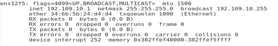
2. Configure the VLAN and IP address on the port connected to a shared uplink port network, as shown in the figure below.
Figure 39 Configuring the IP address on the port connected to a shared uplink port network
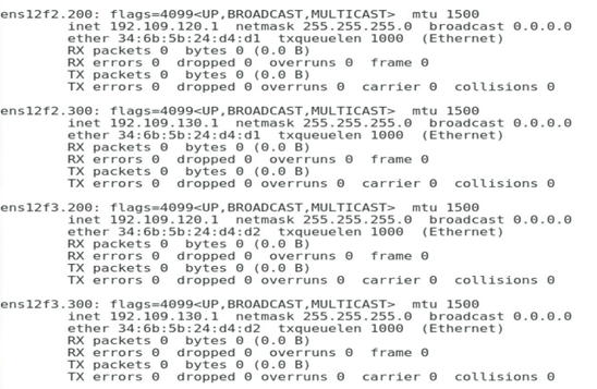
3. Configure the VLAN and IP address on the port connected to a tunnel network, as shown in the figure below.
Figure 40 Configuring the IP address on the port connected to a tunnel network
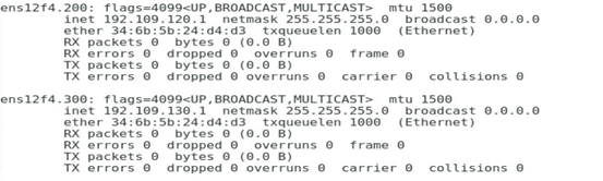
Verifying the configuration
1. The gateway address of VLAN 200 of the R&D Department can communicate with the VLAN 200 address of PF 2 normally, as shown in the figure below.
Figure 41 Checking whether the VLAN 200 network on Port 1 is normal
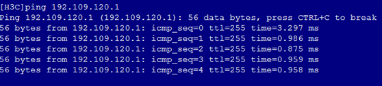
2. The gateway address of VLAN 300 of the R&D Department can communicate with the VLAN 300 address of PF 2 normally, as shown in the figure below.
Figure 42 Checking whether the VLAN 300 network on Port 1 is normal

3. The gateway address of VLAN 200 of the Quality Department can communicate with the VLAN 200 address of PF 3 normally, as shown in the figure below.
Figure 43 Checking whether the VLAN 200 network on Port 3 is normal
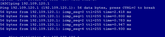
4. The gateway address of VLAN 300 of the Quality Department can communicate with the VLAN 300 address of PF 3 normally, as shown in the figure below.
Figure 44 Checking whether the VLAN 300 network on Port 3 is normal
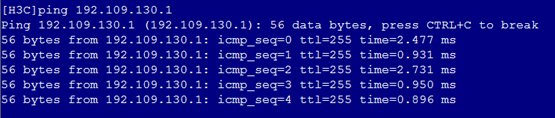
5. The gateway address of VLAN 200 of the Marketing Department can communicate with the VLAN 200 address of PF 4 normally, as shown in the figure below.
Figure 45 Checking whether the VLAN 200 network on Port 4 is normal
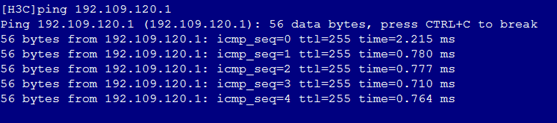
6. The gateway address of VLAN 300 of the Marketing Department can communicate with the VLAN 300 address of PF 4 normally, as shown in the figure below.
Figure 46 Checking whether the VLAN 300 network on Port 4 is normal
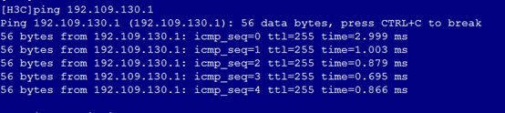
7. The gateway address of the O&M Department can communicate with the IP address of PF 5 normally, as shown in the figure below.
Figure 47 Checking whether the network is normal on Port 5
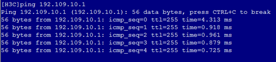
8. Cross-verify that services between departments are isolated from each other.
Example: Configuring a VC profile on the OM Web page in the non QinQ scenario – 1.02.xx or later
Network requirements
As shown in Figure 48, a blade server and an ICM are installed in the H3C B16000 blade server chassis.
· The blade server is installed in slot 8. The Mezz NIC is installed in the slot of Mezz 1 at the rear of the blade server.
· Two ICMs are installed in slots of ICM 1. Ten-GigabitEthernet1/1/9 and Ten-GigabitEthernet1/1/10 of ICM 1 are connected to XGE1/0/9 and XGE1/0/10 of TOR-A switch. Ten-GigabitEthernet1/1/11 and Ten-GigabitEthernet1/1/12 of ICM 1 are connected to XGE1/0/11 and XGE1/0/12 of TOR-B switch.
In this example, the blade server used is H3C UniServer B5700 G3, the Mezz NIC used is NIC-ETH682i-Mb-2*25G (ETH682i for short), and the ICM used is H3C UniServer BX720EF.
A VC profile needs to be configured so that different departments of the company can access different services on the blade server. The specific requirements are as follows:
· Allocate business departments to VLAN 200 and VLAN 300, and the gateway addresses are 192.109.120.2 and 192.109.130.2. These departments need to access service resources in VLAN 200 and VLAN 300 on Port 1 of the blade server, and the service IP addresses are 192.109.120.1 and 192.109.130.1.
· The O&M Department is configured with any VLAN, and the gateway address is 192.109.10.2. It needs to access service resources on Port 1 of the blade server, and the service IP address is 192.109.10.1.
· Isolate networks of these departments from each other.
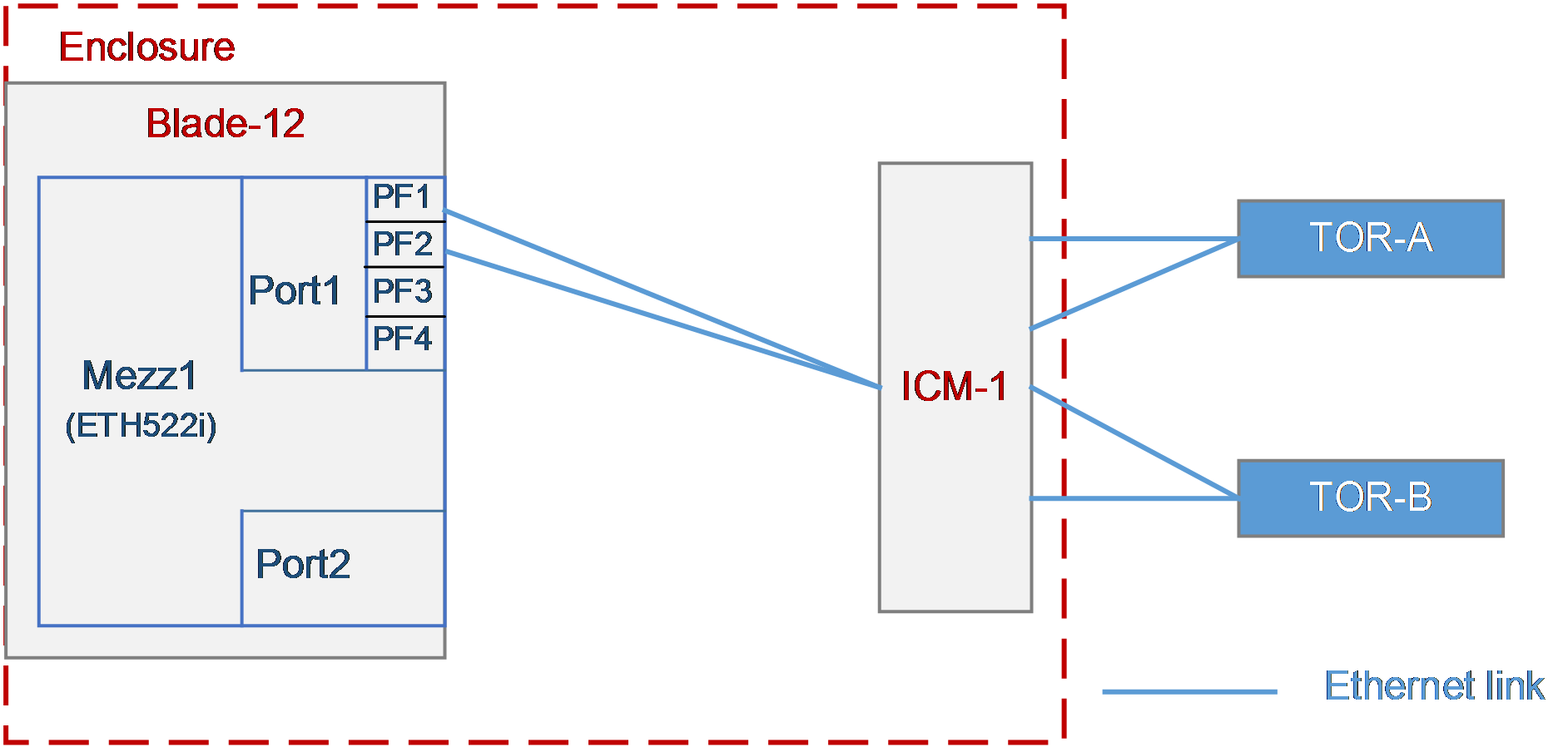
Analysis
· To ensure that these departments can communicate with each other, the packets with the VLAN 100 and VLAN 200 tags on ports PF 1 and PF 2 of the Mezz NIC in Blade 12 must be sent to the ports of the TOR switch through the external ports of ICM 1.
· To ensure the isolation of services between different departments, the S-VLAN values must be different after VLAN mapping. Therefore, make sure to use different VLAN values for different networks on the same ICM.
Software versions used
In this example, data is configured and verified on the ICM (UN_BLADE-SWITCH_SYS-1.03.06) and OM (UN_BLADE-OM-1.03.06).
Procedures
Configuring the NIC in BIOS
1. As shown in the figure below, select the Advanced tab of BIOS, and enter the NIC configuration page.
Figure 49 NIC configuration page
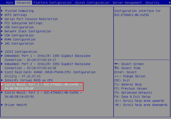
2. As shown in the figure below, set Partitioning Mode to NPAR.
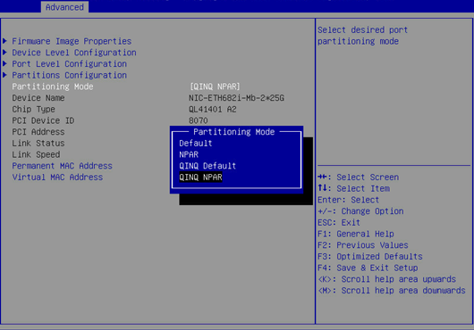
3. As shown in the figure below, select Save Changes and Exit.
Figure 50 Saving the configuration and exiting
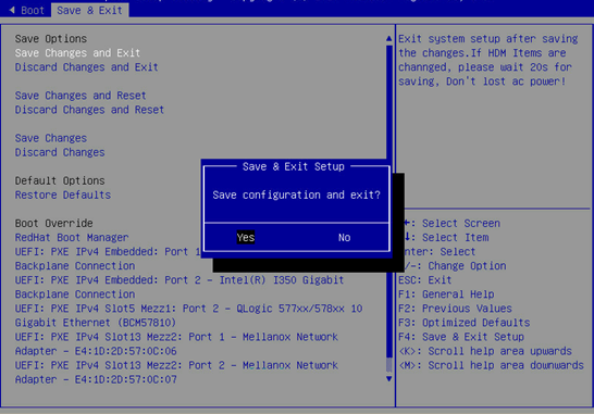
Configuring the ICM in the shared uplink port network
Configuring the VLANs and VLAN mapping for the internal port of the ICM
# Access the internal port of the ICM.
<H3C>system-view
[H3C]int Ten-GigabitEthernet 1/0/15
# Set the port to the trunk mode.
[H3C-Ten-GigabitEthernet1/0/15]port link-type trunk
[H3C-Ten-GigabitEthernet1/0/15]undo port trunk permit vlan 1
# Enable the port to allow the reserved VLAN 2002 on the external port of the ICM.
[H3C-Ten-GigabitEthernet1/0/15]port trunk permit vlan 2002
# Configure VLAN mapping. Implement 1:2 VLAN mapping on the internal port.
[H3C-Ten-GigabitEthernet1/0/15]vlan mapping egress outer-vlan 2002 inner-vlan 200 translated-vlan 200
[H3C-Ten-GigabitEthernet1/0/15]vlan mapping egress outer-vlan 2002 inner-vlan 300 translated-vlan 300
Configuring the VLANs and VLAN mapping for the external port of the ICM
# Create a port isolation group.
<H3C>system-view
[H3C]port-isolate group 1
# Configure the external port 1/1/9 of the ICM.
[H3C]interface range Ten-GigabitEthernet 1/1/9 Ten-GigabitEthernet 1/1/10
[H3C-if-range]port link-type hybrid
[H3C-if-range]undo port hybrid vlan 1
# Untag the VLAN 2002 reserved for the external port of the ICM.
[H3C-if-range]port hybrid vlan 2002 untagged
# Configure VLAN mapping. Implement 1:2 VLAN mapping on the external port.
[H3C-if-range]vlan mapping nest single 200 300 nested-vlan 2002
# Configure port isolation.
[H3C-if-range]port-isolate enable group 1
Configuring the ICM in a common network
Configuring the VLANs and VLAN mapping for the internal port of the ICM
# Set the port to the trunk mode.
<H3C> system-view
[H3C]int Ten-GigabitEthernet 1/0/15
[H3C-Ten-GigabitEthernet1/0/15]port link-type trunk
[H3C-Ten-GigabitEthernet1/0/15]undo port trunk permit vlan 1
# Enable the port to allow the reserved VLAN 2001 on the external port of the ICM.
[H3C-Ten-GigabitEthernet1/0/15]port trunk permit vlan 2001
# Configure VLAN mapping. Implement 0:2 VLAN mapping on the internal port.
[H3C-Ten-GigabitEthernet1/0/15] vlan mapping untagged nested-outer-vlan 2001 nested-inner-vlan 4094
Configuring the VLANs and VLAN mapping for the external port of the ICM
# Create a port isolation group.
<H3C>system-view
[H3C]port-isolate group 1
# Configure the external port of the ICM.
[H3C]interface range Ten-GigabitEthernet 1/1/11 Ten-GigabitEthernet 1/1/12
[H3C-if-range]port link-type hybrid
[H3C-if-range]undo port hybrid vlan 1
# Untag the VLAN 2001 reserved for the external port of the ICM.
[H3C-if-range]port hybrid vlan 2001 untagged
# Configure VLAN mapping. Implement 0:2 VLAN mapping on the external port.
[H3C-if-range]vlan mapping untagged nested-outer-vlan 2001 nested-inner-vlan 4094
# Configure port isolation.
[H3C-if-range]port-isolate enable group 1
Configuring the connection mode of the network uplink port
Configuring the connection mode of the uplink port as active/standby
# Create a Smart-Link group and add ports 1/1/9 and 1/1/10 to the Smart-Link group.
<H3C> system-view
[H3C]smart-link group 11
[H3C-smlk-group11]protected-vlan reference-instance 0
[H3C-smlk-group11]interface Ten-GigabitEthernet1/1/9
[H3C-Ten-GigabitEthernet1/1/9]port smart-link group 11 primary
[H3C-Ten-GigabitEthernet1/1/9]interface Ten-GigabitEthernet1/1/10
[H3C-Ten-GigabitEthernet1/1/10]port smart-link group 11 secondary
Configuring the connection mode of the uplink port as static aggregation
# The configuration of aggregation port is consistent with that of member port.
<H3C> system-view
[H3C]interface Bridge-Aggregation2009
[H3C-Bridge-Aggregation2009]port link-type hybrid
[H3C-Bridge-Aggregation2009]undo port hybrid vlan 1
[H3C-Bridge-Aggregation2009]port hybrid vlan 2001 untagged
[H3C-Bridge-Aggregation2009]vlan mapping nest single 200 300 nested-vlan 2002
# The port isolation configuration is available for the member port by default, but needs to be manually added for the aggregation port.
[H3C-Bridge-Aggregation2009]port-isolate enable group 1
[H3C-Bridge-Aggregation2009]quit
# Add the member port to the aggregation group.
[H3C]interface range Ten-GigabitEthernet 1/1/11 Ten-GigabitEthernet 1/1/12
[H3C-if-range]port link-aggregation group 2009
Configuring the TOR switch
Configuring the TOR-A switch
# Create VLANs 200 and 300.
[H3C] vlan200 300
# Configure the interface to allow the traffic of VLANs 200 and 300 to pass through.
[H3C] interface Ten-GigabitEthernet 1/0/9
[H3C-Ten-GigabitEthernet1/0/9] port link-type trunk
[H3C-Ten-GigabitEthernet1/0/9] port trunk permit vlan 1 200 300
[H3C-Ten-GigabitEthernet1/0/9] undo stp enable
[H3C-Ten-GigabitEthernet1/0/9] quit
[H3C] interface Ten-GigabitEthernet 1/0/10
[H3C-Ten-GigabitEthernet1/0/10] port link-type trunk
[H3C-Ten-GigabitEthernet1/0/10] port trunk permit vlan 1 200 300
[H3C-Ten-GigabitEthernet1/0/10] undo stp enable
[H3C-Ten-GigabitEthernet1/0/10] quit
# Create the VLAN 200 interface, and set the IP address of this interface to 192.109.120.2/24.
[H3C] interface vlan 200
[H3C-VLAN-interface200] ip address 192.109.120.2 255.255.255.0
[H3C-VLAN-interface200] quit
# Create the VLAN 300 interface, and set the IP address of this interface to 192.109.130.2/24.
[H3C] interface vlan 300
[H3C-VLAN-interface300] ip address 192.109.130.2 255.255.255.0
[H3C-VLAN-interface300] quit
# Check the VLAN interface status and confirm that the interface is UP.
[H3C]display interface vlan 200 brief
Brief information on interfaces in route mode:
Link: ADM - administratively down; Stby - standby
Protocol: (s) - spoofing
Interface Link Protocol Primary IP Description
VLAN200 UP UP 192.109.120.2
[H3C]display interface vlan 300 brief
Brief information on interfaces in route mode:
Link: ADM - administratively down; Stby - standby
Protocol: (s) - spoofing
Interface Link Protocol Primary IP Description
VLAN300 UP UP 192.109.130.2
# Save the configuration.
[H3C] save
The current configuration will be written to the device. Are you sure? [Y/N]:y
Please input the file name(*.cfg)[flash:/startup.cfg]
To leave the existing filename unchanged, press the enter key.
Configuring the TOR-B switch
# Create VLANs 200 and 300.
[H3C] vlan200 300
# Configure the interface to allow the traffic of VLANs 200 and 300 to pass through.
[H3C] int Bridge-Aggregation 30
[H3C-Bridge-Aggregation30]
[H3C] interface Ten-GigabitEthernet 1/0/11
[H3C-Ten-GigabitEthernet1/0/11] port link-aggregation group 30
[H3C-Ten-GigabitEthernet1/0/11] quit
[H3C] interface Ten-GigabitEthern 1/0/12
[H3C-Ten-GigabitEthernet1/0/12] port link-aggregation group 30
[H3C-Ten-GigabitEthernet1/0/12] quit
# Create the VLAN 300 interface, and set the IP address of this interface to 192.109.130.2/24.
[H3C] interface vlan 1
[H3C-VLAN-interface300] ip address 192.109.10.2 255.255.255.0
[H3C-VLAN-interface300] quit
# Check the VLAN interface status and confirm that the interface is UP.
[H3C]display interface vlan 1 brief
Brief information on interfaces in route mode:
Link: ADM - administratively down; Stby - standby
Protocol: (s) - spoofing
Interface Link Protocol Primary IP Description
VLAN1 UP UP 192.109.10.2
# Save the configuration.
[H3C] save
The current configuration will be written to the device. Are you sure? [Y/N]:y
Please input the file name(*.cfg)[flash:/startup.cfg]
To leave the existing filename unchanged, press the enter key.
Configuring each service IP address
1. Configure the VLAN and IP address on the port connected to a common network, as shown in the figure below.
Figure 51 Configuring the IP address on the port connected to a common network
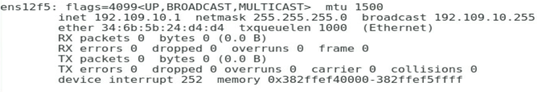
2. Configure the VLAN and IP address on the port connected to a shared uplink port network, as shown in the figure below.
Figure 52 Configuring the IP address on the port connected to a shared uplink port network
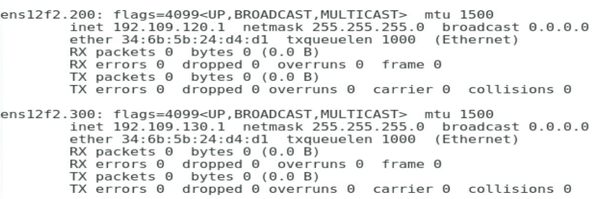
Verifying the configuration
1. The gateway address of VLAN 200 of the R&D Department can communicate with the VLAN 200 address of Port 2 normally, as shown in the figure below.
Figure 53 Checking whether the VLAN 200 network on Port 1 is normal
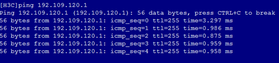
2. The gateway address of VLAN 300 of the R&D Department can communicate with the VLAN 300 address of Port 2 normally, as shown in the figure below.
Figure 54 Checking whether the VLAN 300 network on Port 1 is normal
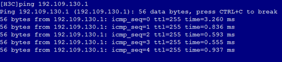
3. The gateway address of the O&M Department can communicate with the IP address of Port 5 normally, as shown in the figure below.
Figure 55 Checking whether the network is normal on Port 5