- Table of Contents
-
- H3C UniServer B16000 Blade Server Configuration Examples-6W100
- 01-FC and FCoE Services Configuration Examples
- 02-Ethernet Services Configuration Examples
- 03-Virtual Management Network Configuration Examples
- 04-Shared Storage Configuration Examples
- 05-VC Configuration Examples
- 06-Chassis Profile Configuration Examples
- 07-IB Service Configuration Examples
- 08-Blade Server FIST Configuration Examples
- Related Documents
-
| Title | Size | Download |
|---|---|---|
| 03-Virtual Management Network Configuration Examples | 1.18 MB |
Contents
Example: Configuring the virtual management network (through interconnect modules)
Configuring the ports on the mezzanine card under the OS
Configuring the interconnect module
Configuring the aggregation switch
Example: Configuring the virtual management network (through OM modules)
Configuring an onboard network adapter under the OS
Configuring the ports on the OM modules
Configuring the aggregation switch
Introduction
The following information provides examples for configuring virtual management networks for the H3C UniServer B16000 blade server chassis.
Hardware compatibility
Table 1 lists the hardware to be used in typical networking modes. If there are multiple models in a cell, the hardware of these models is appropriate for this configuration.
Table 1 Hardware compatibility
|
Configuration example |
Hardware compatibility |
|||
|
NIC |
Interconnect module |
External switch |
Backend storage |
|
|
Example: Configuring the virtual management network (through interconnect modules) |
· ETH521i · ETH522i · ETH561i · ETH640i · ETH681i · ETH682i |
· BX720EF · BX1020EF · BX720E · BX1010E |
Ethernet switch |
NA |
|
Example: Configuring the virtual management network (through OM modules) |
Onboard network adapter |
NA |
Ethernet switch |
NA |
Prerequisites
The configuration examples were created and verified in a lab environment, and all the devices were started with the factory default configuration. When you are working on a live network, make sure you understand the potential impact of every command on your network.
The following information is provided based on the assumption that you have basic knowledge of virtualization, port aggregation features, H3C blade servers, interconnect modules, and Windows/Linux/ESXi/CAS operating systems.
The following information mainly describes the procedure for configuring the blade server chassis. As a best practice, configure external network settings as needed.
Example: Configuring the virtual management network (through interconnect modules)
Network configuration
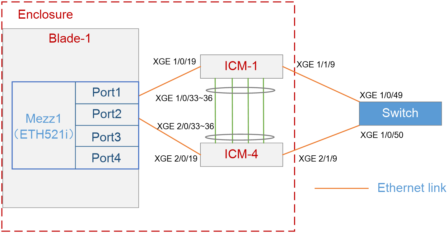
As shown in Figure 1, in the H3C B16000 blade server chassis, the blade server is installed in slot 1, and two interconnect modules are installed in slot 1 and slot 4. A mezzanine card is installed in the mezzanine card slot 1 of the blade server. The two interconnect modules are directly connected to the same aggregation switch through external ports.
In this example, the following devices and modules are used: blade server (H3C UniServer B5700 G3), mezzanine card (NIC-ETH521i-Mb-4*10G, "ETH521i"), interconnect module (BX720E), and operating system (CAS0526).
The following requirements are expected to be met:
Through the interconnect modules, users can log in to the virtual management network under the CAS operating system of the blade server, and the network is redundant.
Analysis
To improve the reliability of links over ports on the mezzanine card, you need to aggregate Port 1 and Port 2 in the active/standby mode in the OS.
Software versions used
This example was created and verified on SWITCH_SYS-1.00.11 and OM-1.00.11 versions.
Procedures
Querying port information
Querying port information and confirming the ports to be configured
Query the correspondence among mezzanine cards, internal ports of interconnect modules, and network adapters of the OS according to "Querying port relations."
It can be learned that:
· In this example, Port 1 and Port 2 of mezzanine card 1 are used and are named eth2 and eth3 under the OS, respectively.
· Ten-gigabitethernet 1/0/19 ports of interconnect modules 1 and 4 are used in this example.
Configuring the ports on the mezzanine card under the OS
1. As shown in Figure 2, log in to the CAS operating system of the blade server through the KVM through the remote control function on the OM Web page.
Figure 2 Logging in to the CAS operating system through the KVM
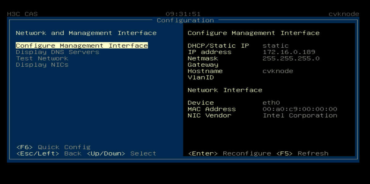
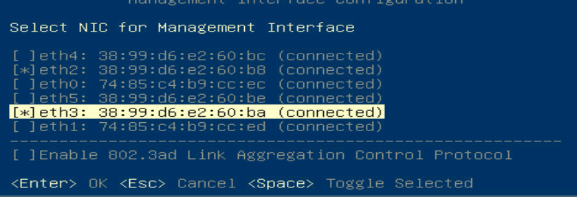
2. As shown in Figure 3, on the main page of the CAS OS, select Network and Management Interface to enter the network adapter selection page and bind the OS to the two selected ports on the mezzanine card.
Figure 3 Binding the CAS OS to the selected ports
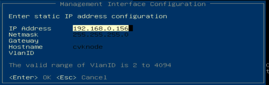
3. As shown in Figure 4, configure the IP address of the CAS OS on the bound ports.
Figure 4 Configuring the IP address of the CAS OS
|
|
NOTE: In this example, Gateway and VlanID are not configured. If necessary, please configure them according to the actual situation. |
Configuring the interconnect module
Interconnect the interconnect module and the aggregation switch. # Create a layer-2 aggregation port, and add the physical ports to the port.
[H3C]int Bridge-Aggregation 10
[H3C-Bridge-Aggregation10]
[H3C]interface Ten-GigabitEthernet 1/1/9
[H3C-Ten-GigabitEthernet1/1/9]port link-aggregation group 10
[H3C-Ten-GigabitEthernet1/1/9]quit
[H3C]interface Ten-GigabitEthernet 2/1/9
[H3C-Ten-GigabitEthernet2/1/9]port link-aggregation group 10
[H3C-Ten-GigabitEthernet2/1/9]quit
[H3C]save
The current configuration will be written to the device. Are you sure? [Y/N]:y
Please input the file name(*.cfg)[flash:/startup.cfg]
(To leave the existing filename unchanged, press the enter key)
|
|
NOTE: If VLAN is required in the uplink and downlink, you need to configure VLAN-related settings on the aggregation port of the interconnect module according to the actual situation. |
Configuring the aggregation switch
1. In the command line view of the aggregation switch, create a layer-2 aggregation port, add the external physical ports of the interconnect module to the aggregation group, and save the configuration.
[H3C]int Bridge-Aggregation 10
[H3C-Bridge-Aggregation10]
[H3C]interface Ten-GigabitEthernet 1/0/49
[H3C-Ten-GigabitEthernet1/0/49]port link-aggregation group 10
[H3C-Ten-GigabitEthernet1/0/49]quit
[H3C]interface Ten-GigabitEthern1/0/50
[H3C-Ten-GigabitEthernet1/0/50]port link-aggregation group 10
[H3C-Ten-GigabitEthernet1/0/50]quit
[H3C]save
The current configuration will be written to the device. Are you sure? [Y/N]:y
Please input the file name(*.cfg)[flash:/startup.cfg]
(To leave the existing filename unchanged, press the enter key):
2. You can view the information about the aggregation port and confirm that the aggregation port has been created.
[H3C] display link-aggregation verbose Bridge-Aggregation 10
Loadsharing Type: Shar -- Loadsharing, NonS -- Non-Loadsharing
Port Status: S -- Selected, U -- Unselected, I -- Individual
Port: A -- Auto port, M -- Management port, R -- Reference port
Flags: A -- LACP_Activity, B -- LACP_Timeout, C -- Aggregation,
D -- Synchronization, E -- Collecting, F -- Distributing,
G -- Defaulted, H -- Expired
Aggregate Interface: Bridge-Aggregation10
Aggregation Mode: Static
Loadsharing Type: Shar
Management VLANs: None
Port Status Priority Oper-Key
XGE1/0/49 U 32768 1
XGE1/0/50 S 32768 1
Verifying the configuration
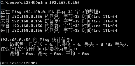
1. Set the IP address of the local PC to and address with the same network segment as the IP address of the CAS OS. As shown in Figure 5, the IP address of the CAS OS can be successfully pinged through the local PC.
Figure 5 Pinging the IP address of the CAS OS through the local PC
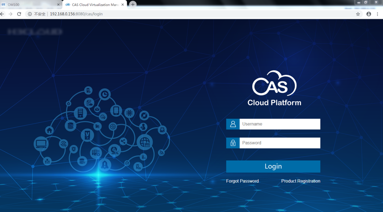
2. As shown in Figure 6, you can log in to the management web page by entering 192.168.0.156: 8080/CAS in the local PC browser.
Figure 6 Web page of the CAS OS
Example: Configuring the virtual management network (through OM modules)
Network configuration
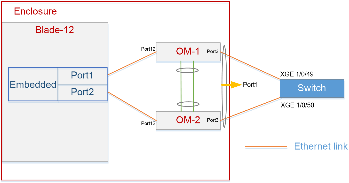
As shown in Figure 7, in the H3C B16000 blade server chassis, the blade server is installed in slot 12, and two OM modules are installed in place. The OS is installed in the blade server. The two OM modules are directly connected to the same aggregation switch through external service ports.
In this example, the blade server (H3C UniServer B5700 G3) and the operating system (VMware ESXI6.7U1) are used.
The following requirements are expected to be met:
Through the external service ports of OM modules, users can log in to the virtual management network under the ESXi operating system of the blade server, and the network is redundant.
Analysis
· By default, the two OM modules form an active/standby relation automatically through internal ports, thus ensuring the redundancy of the OM modules.
· When no special VLAN configuration is required, you must configure the VLAN policy of the OM modules and set the PVID of internal and external ports to VLAN1, to ensure layer-2 link communication.
· To improve the downlink reliability of the OM modules, you must add the external ports of the two OM modules to the aggregation port.
Software versions used
This example was created and verified on SWITCH_SYS-1.00.11 and OM-1.00.11 versions.
Procedures
Configuring an onboard network adapter under the OS
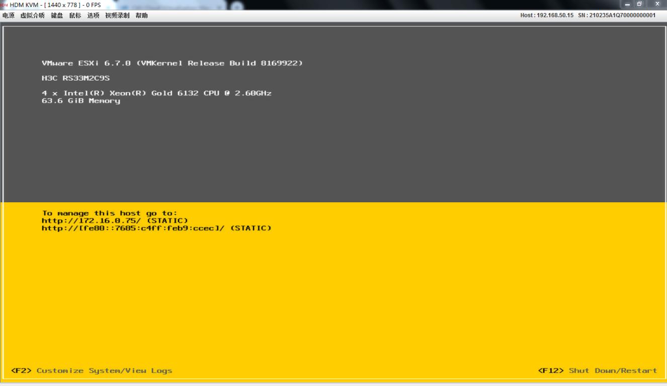
1. As shown in Figure 8, log in to the VMware ESXi operating system of the blade server through the KVM through the remote control function on the OM Web page.
Figure 8 Logging in to the VMware ESXi operating system through the KVM
2. As shown in Figure 9, press F2 on the main page, enter the account name and password to enter the operating system configuration page, and select Configure Management Network.
Figure 9 Configuring the VMware ESXi operating system
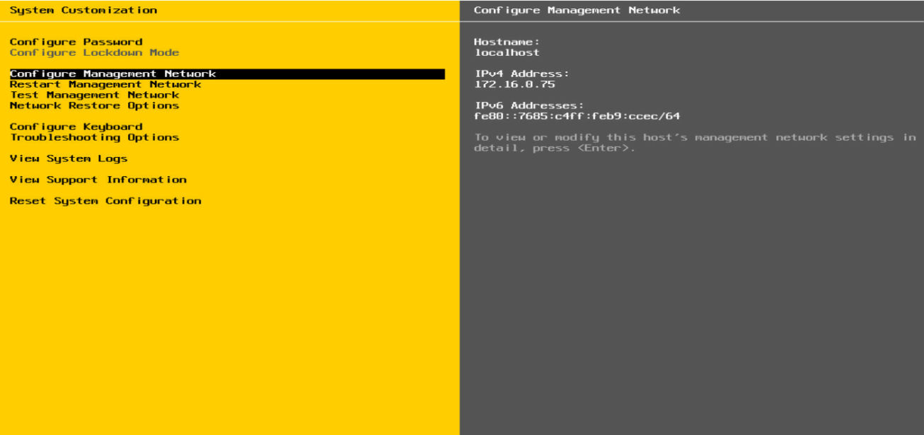
3. On the operating system configuration page, select Configure Management Network. As shown in Figure 10, enter the management network configuration page.
Figure 10 Configuring the management network under the VMware ESXi operating system
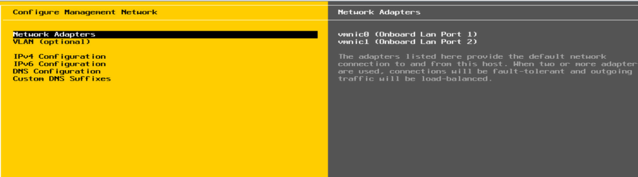
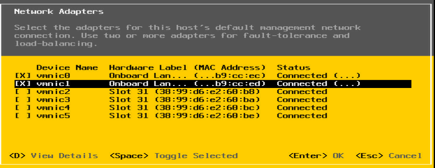
4. On the management network configuration page, select Network Adapters. As shown in Figure 11, enter the network adapter port configuration page, and select vmnic0 and vmnic1 to bind the ports.
|
|
NOTE: When selecting the ports on the port configuration page, select onboard ports in the Hardware Label column. Here we use vmnic0 and vmnic1 as an example. |
Figure 11 Configuring the ports on the network adapter under the VMware ESXi operating system
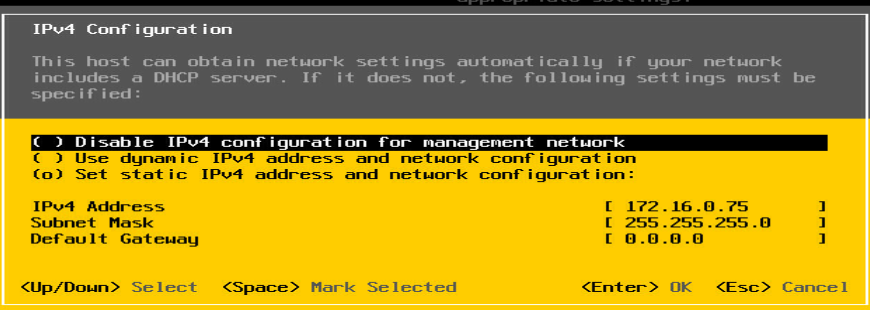
5. As shown in Figure 12, configure the IP address of the management network.
Configuring the ports on the OM modules
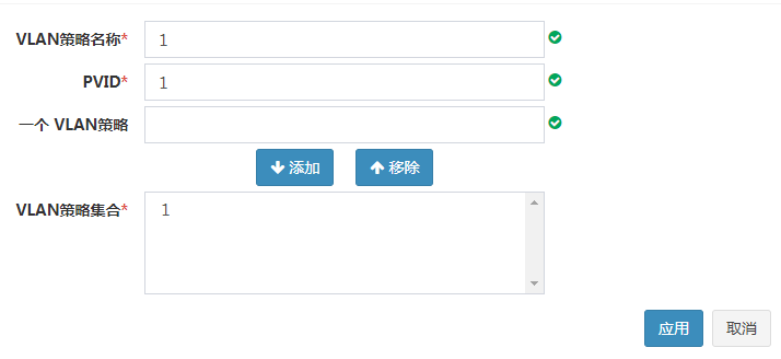
1. As shown in Figure 13, on the OM Web page, click OM Module > Service Module > Port Mapping > VLAN Policy > Add, enter relevant parameters, and apply the VLAN policy.
Figure 13 Configuring a VLAN policy
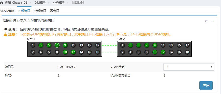
2. As shown in Figure 14, click Internal Ports, select the internal port 12 of OM module 1 and the same port of OM module 2 in the view, and apply the VLAN policy you just created.
Figure 14 Applying the VLAN policy to internal ports
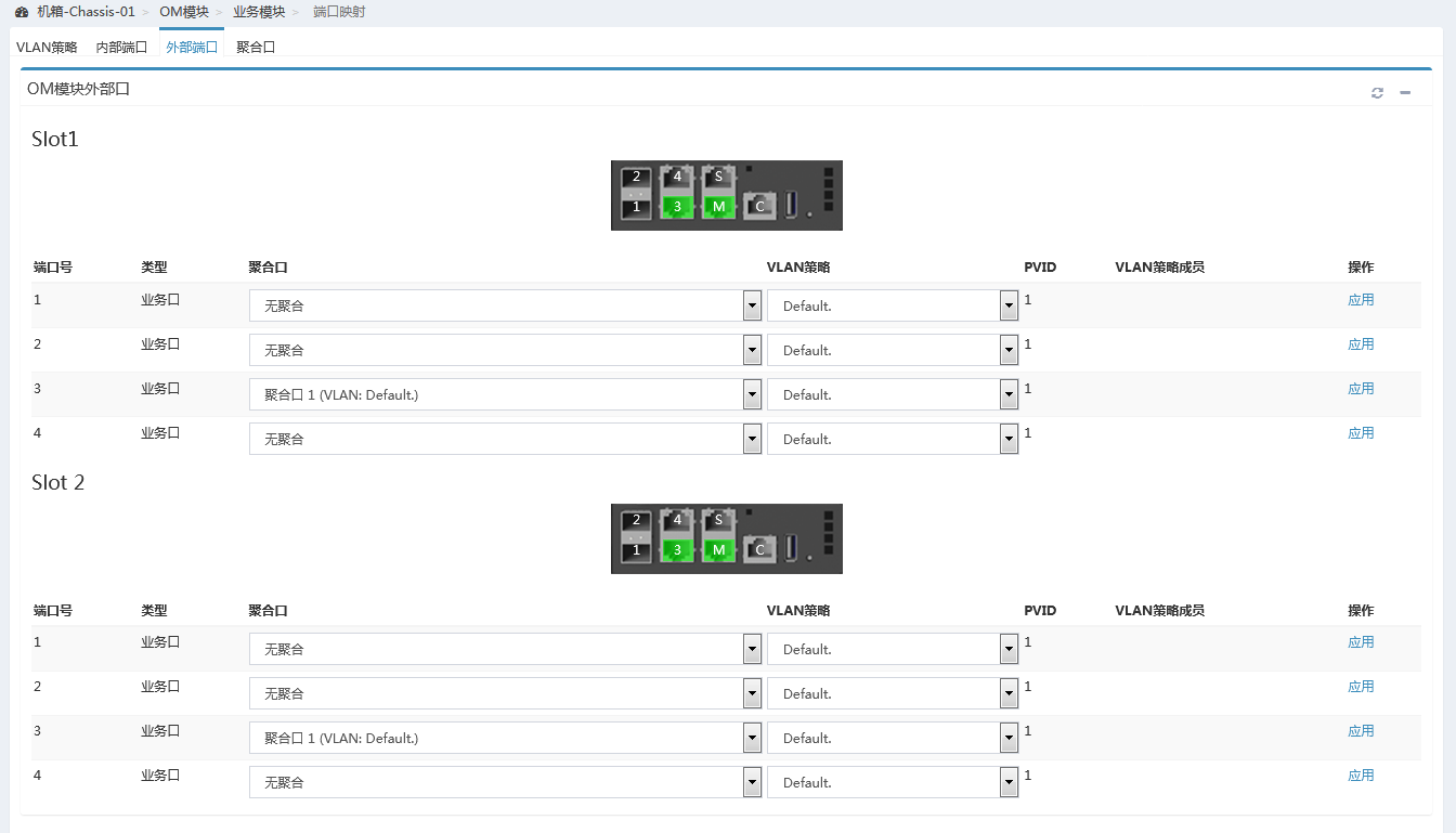
3. As shown in Figure 15, click External Ports, and add the external port 3 of OM module 1 and the same port of OM module 2 to aggregation port 1.
Figure 15 Adding the external ports to the aggregation port
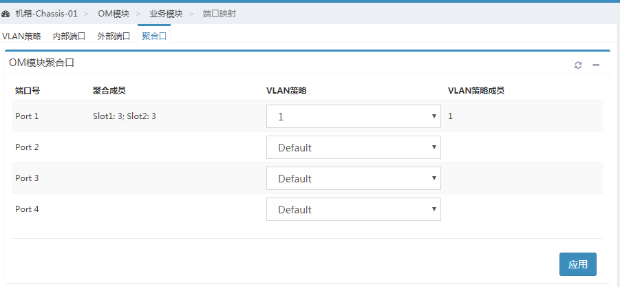
4. As shown in Figure 16, click Aggregation Port to apply the VLAN policy you just created on aggregation port 1.
Figure 16 Applying the VLAN policy to the aggregation port
Configuring the aggregation switch
1. In the command line view of the aggregation switch, create a layer-2 aggregation port, add the external physical ports of the interconnect module to the aggregation group, and save the configuration.
[H3C]int Bridge-Aggregation 10
[H3C-Bridge-Aggregation10]
[H3C]interface GigabitEthernet 1/0/49
[H3C-GigabitEthernet1/0/49] port link-aggregation group 10
[H3C-GigabitEthernet1/1/1] quit
[H3C]interface GigabitEthern 1/0/50
[H3C-GigabitEthernet1/0/50]port link-aggregation group 10
[H3C-GigabitEthernet1/0/50]quit
[H3C]save
The current configuration will be written to the device. Are you sure? [Y/N]:y
Please input the file name(*.cfg)[flash:/startup.cfg]
(To leave the existing filename unchanged, press the enter key):
2. You can view the information about the aggregation port and confirm that the aggregation port has been created.
[H3C] display link-aggregation verbose Bridge-Aggregation 10
Loadsharing Type: Shar -- Loadsharing, NonS -- Non-Loadsharing
Port Status: S -- Selected, U -- Unselected, I -- Individual
Port: A -- Auto port, M -- Management port, R -- Reference port
Flags: A -- LACP_Activity, B -- LACP_Timeout, C -- Aggregation,
D -- Synchronization, E -- Collecting, F -- Distributing,
G -- Defaulted, H -- Expired
Aggregate Interface: Bridge-Aggregation10
Aggregation Mode: Static
Loadsharing Type: Shar
Management VLANs: None
Port Status Priority Oper-Key
XGE1/0/49 U 32768 1
XGE1/0/50 S 32768 1
Verifying the configuration
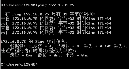
1. Set the IP address of the local PC to an address with the same network segment as the IP address of the VMware ESXi operating system. As shown in Figure 17, the IP address of the VMware ESXi operating system can be successfully pinged through the local PC.
Figure 17 Pinging the IP address of the VMware ESXi operating system through the local PC
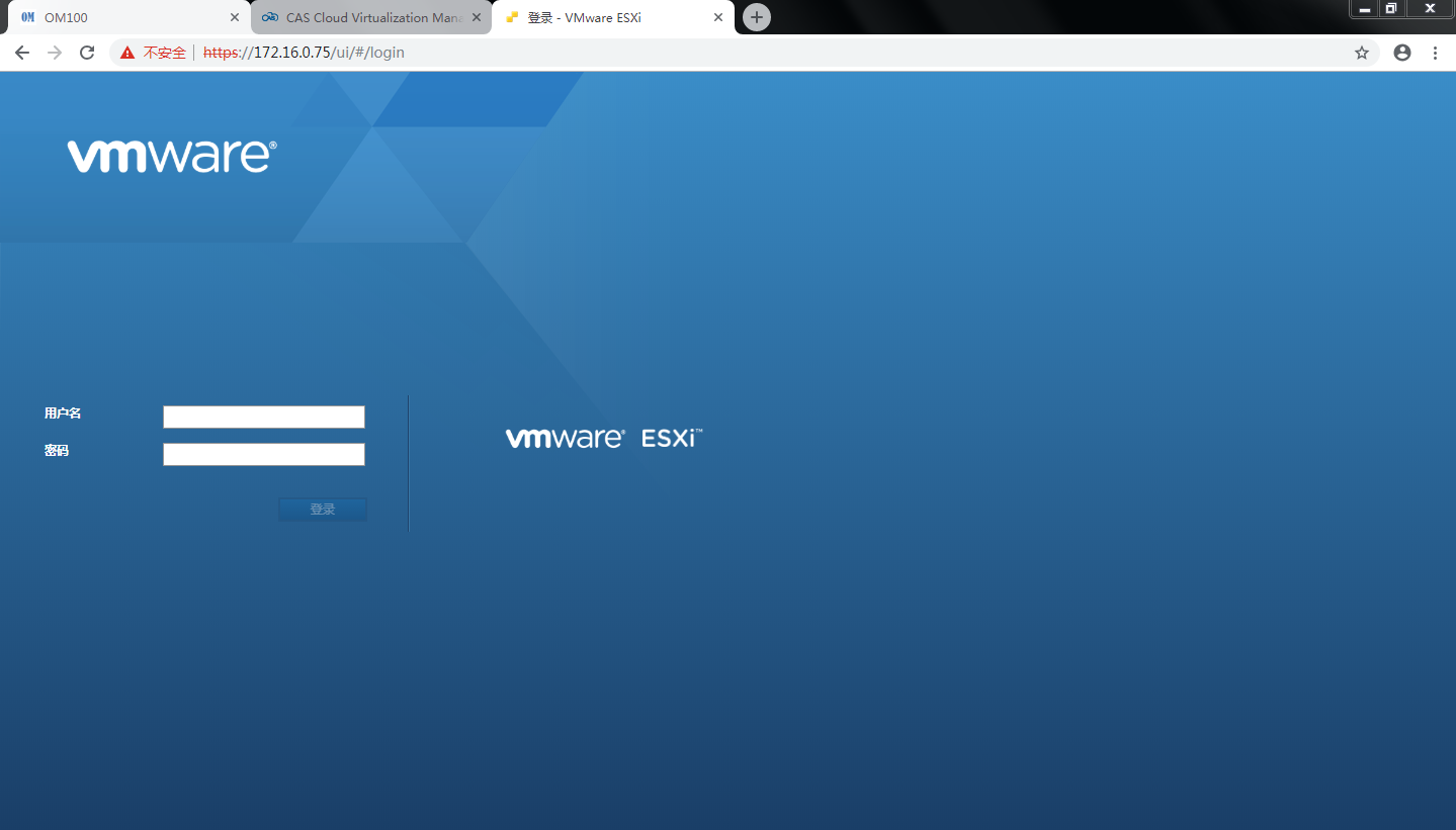
2. As shown in Figure 18, you can log in to the management web page by the IP address of the VMware ESXi operating system in the local PC browser.
Figure 18 Logging in to the VMware ESXi web page
Common operations
Querying port relations
Query the interface connection between mezzanine cards and interconnect modules
Please use the H3C networking query tool on the official website to view the port connection relation between mezzanine cards and interconnect modules.
Query the MAC address or WWN number of the mezzanine card.
Log in to the OM Web page and click Blade Server Management/Target Blade Server/Port Mapping to view the port MAC address of the Ethernet mezzanine card and the port WWN number of the FC mezzanine card.
Querying the port correspondence between the network adapter and the mezzanine card under the OS
1. To view the MAC addresses of all network adapters, execute the ipconfig -all command in Windows and execute the ifconfig command in Linux.
2. According to the MAC addresses or WWNs queried above, you can learn the correspondence between the ports on the network adapter and the mezzanine card under the OS.
