- Table of Contents
-
- 06-Security Configuration Guide
- 00-Preface
- 01-AAA Configuration
- 02-802.1X Configuration
- 03-MAC Authentication Configuration
- 04-Triple Authentication Configuration
- 05-Port Security Configuration
- 06-User Profile Configuration
- 07-HABP Configuration
- 08-Public Key Configuration
- 09-PKI Configuration
- 10-SSH2.0 Configuration
- 11-SSL Configuration
- 12-TCP Attack Protection Configuration
- 13-IP Source Guard Configuration
- 14-ARP Attack Protection Configuration
- 15-ND Attack Defense Configuration
- Related Documents
-
| Title | Size | Download |
|---|---|---|
| 14-ARP Attack Protection Configuration | 187.75 KB |
Contents
ARP attack protection configuration
ARP attack protection overview
ARP attack protection configuration task list
Configuring ARP packet rate limit
Configuring ARP packet rate limit
Configuring source MAC address based ARP attack detection
Displaying and maintaining source MAC address based ARP attack detection
Configuring ARP packet source MAC address consistency check
Configuring ARP active acknowledgement
Configuring ARP detection based on specified objects
Configuring ARP restricted forwarding
Displaying and maintaining ARP detection
ARP detection configuration example I
ARP detection configuration example II
ARP restricted forwarding configuration example
Configuring ARP gateway protection
ARP gateway protection configuration example
ARP filtering configuration example
This chapter includes these sections:
· ARP attack protection overview
· ARP attack protection configuration task list
|
|
NOTE: · The term "switch" or "device" in this chapter refers to the switching engine on a WX3000E wireless switch. · The WX3000E series comprises WX3024E and WX3010E wireless switches. · The port numbers in this chapter are for illustration only. |
ARP attack protection overview
Although ARP is easy to implement, it provides no security mechanism and thus is prone to network attacks. An attacker may send:
· ARP packets by acting as a trusted user or gateway so that the receiving devices obtain incorrect ARP entries.
· A large number of IP packets with unreachable destinations. As a result, the receiving device continuously resolves destination IP addresses and thus its CPU is overloaded.
· A large number of ARP packets to overload the CPU of the receiving device.
For more information about ARP attack features and types, see ARP Attack Protection Technology White Paper.
ARP attacks and viruses are threatening LAN security. This chapter introduces multiple features to detect and prevent such attacks.
ARP attack protection configuration task list
Complete the following tasks to configure ARP attack protection:
|
Task |
Remarks |
|
Optional Configure this function on gateways (recommended). |
|
|
Optional Configure this function on gateways (recommended). |
|
|
Optional Configure this function on access devices (recommended). |
|
|
Optional Configure this function on access devices (recommended). |
|
|
Optional Configure this function on access devices (recommended). |
Configuring ARP packet rate limit
Introduction
The ARP packet rate limit feature allows you to limit the rate of ARP packets to be delivered to the CPU on a switch. For example, if an attacker sends a large number of ARP packets to an ARP detection enabled device, the CPU of the device will be overloaded because all the ARP packets are redirected to the CPU for checking. As a result, the device fails to deliver other functions properly or even crashes. To solve this problem, you can configure ARP packet rate limit.
Enable this feature after the ARP detection is configured, or use this feature to prevent ARP flood attacks.
Configuring ARP packet rate limit
Follow these steps to configure ARP packet rate limit:
|
To do… |
Use the command… |
Remarks |
|
Enter system view |
system-view |
— |
|
Enter Ethernet interface or Layer 2 aggregate interface view |
interface interface-type interface-number |
— |
|
Configure or disable ARP packet rate limit |
arp rate-limit { disable | rate pps drop } |
Required The default setting is disable. |
Configuring source MAC address based ARP attack detection
Introduction
This feature checks the number of ARP packets received from the same MAC address within five seconds against a specified threshold. If the threshold is exceeded, the device adds the MAC address in an ARP attack entry. Before the entry is aged out, the device handles the attack by using either of the following methods:
· Monitor—Generates log messages.
· Filter—Generates log messages and filters out subsequent ARP packets from that MAC address.
You can exclude the MAC addresses of some gateways and servers from this detection. This feature does not inspect ARP packets from those devices even if they are attackers.
Configuration procedure
Follow these steps to configure source MAC address based ARP attack detection:
|
To do… |
Use the command… |
Remarks |
|
Enter system view |
system-view |
— |
|
Enable source MAC address based ARP attack detection and specify the detection mode |
arp anti-attack source-mac { filter | monitor } |
Required Disabled by default. |
|
Configure the threshold |
arp anti-attack source-mac threshold threshold-value |
Optional The default setting is 50. |
|
Configure the age timer for ARP attack detection entries |
arp anti-attack source-mac aging-time time |
Optional 300 seconds by default. |
|
Configure protected MAC addresses |
arp anti-attack source-mac exclude-mac mac-address&<1-10> |
Optional No protected MAC address is configured by default. |
|
|
NOTE: After an ARP attack detection entry expires, ARP packets sourced from the MAC address in the entry can be processed normally. |
Displaying and maintaining source MAC address based ARP attack detection
|
To do… |
Use the command… |
Remarks |
|
Display attacking MAC addresses detected by source MAC address based ARP attack detection |
display arp anti-attack source-mac { slot slot-number | interface interface-type interface-number } [ | { begin | exclude | include } regular-expression ] |
Available in any view |
Configuring ARP packet source MAC address consistency check
Introduction
The ARP packet source MAC address consistency check feature enables a gateway device to filter out ARP packets that have a different source MAC address in the Ethernet header from the sender MAC address in the message, so that the gateway device can learn correct ARP entries.
Configuration procedure
Follow these steps to enable ARP packet source MAC address consistency check:
|
To do… |
Use the command… |
Remarks |
|
Enter system view |
system-view |
— |
|
Enable ARP packet source MAC address consistency check |
arp anti-attack valid-check enable |
Required Disabled by default. |
Configuring ARP active acknowledgement
Introduction
The ARP active acknowledgement feature is configured on gateway devices to identify invalid ARP packets.
ARP active acknowledgement works before the gateway creates or modifies an ARP entry to avoid generating any incorrect ARP entry. For more information about its working mechanism, see ARP Attack Protection Technology White Paper.
Configuration procedure
Follow these steps to configure ARP active acknowledgement:
|
To do… |
Use the command… |
Remarks |
|
Enter system view |
system-view |
— |
|
Enable the ARP active acknowledgement function |
arp anti-attack active-ack enable |
Required Disabled by default. |
Configuring ARP detection
Introduction
The ARP detection feature is mainly configured on an access device to allow only the ARP packets of authorized clients to be forwarded and prevent user spoofing and gateway spoofing.
ARP detection includes ARP detection based on static IP source guard binding entries/DHCP snooping entries/802.1X security entries/OUI MAC addresses, ARP detection based on specified objects, and ARP restricted forwarding.
|
|
NOTE: If both the ARP detection based on specified objects and the ARP detection based on static IP source guard binding entries/DHCP snooping entries/802.1X security entries/OUI MAC addresses are enabled, the former one applies first, and then the latter applies. |
Enabling ARP detection based on static IP source guard binding entries/DHCP snooping entries/802.1x security entries/OUI MAC addresses
With this feature enabled, the device compares the sender IP and MAC addresses of an ARP packet received from the VLAN against the static IP source guard binding entries, DHCP snooping entries, 802.1X security entries, or OUI MAC addresses to prevent spoofing.
After you enable this feature for a VLAN,
1. Upon receiving an ARP packet from an ARP untrusted port, the device compares the sender IP and MAC addresses of the ARP packet against the static IP source guard binding entries. If a match is found, the ARP packet is considered valid and is forwarded. If an entry with a matching IP address but an unmatched MAC address is found, the ARP packet is considered invalid and is discarded. If no entry with a matching IP address is found, the device compares the ARP packet’s sender IP and MAC addresses against the DHCP snooping entries, 802.1X security entries, and OUI MAC addresses.
2. If a match is found in any of the entries, the ARP packet is considered valid and is forwarded. ARP detection based on OUI MAC addresses refers to that if the sender MAC address of the received ARP packet is an OUI MAC address and voice VLAN is enabled, the packet is considered valid.
3. If no match is found, the ARP packet is considered invalid and is discarded.
4. Upon receiving an ARP packet from an ARP trusted port, the device does not check the ARP packet.
|
|
NOTE: · Static IP source guard binding entries are created by using the user-bind command. For more information, see the chapter “IP source guard configuration.” · Dynamic DHCP snooping entries are automatically generated through the DHCP snooping function. For more information, see the Layer 3 Configuration Guide. · 802.1X security entries are generated in this case. After a client passes 802.1X authentication and uploads its IP address to an ARP detection enabled device, the device automatically generates an 802.1X security entry. Therefore, the 802.1X client must be able to upload its IP address to the device. For more information, see the chapter “802.1X configuration.” · For more information about voice VLANs and QUI MAC addresses, see the Layer 2 Configuration Guide. |
Follow these steps to enable ARP detection for a VLAN and specify a trusted port:
|
To do… |
Use the command… |
Remarks |
|
Enter system view |
system-view |
— |
|
Enter VLAN view |
vlan vlan-id |
— |
|
Enable ARP detection for the VLAN |
arp detection enable |
Required ARP detection based on static IP source guard binding entries/DHCP snooping entries/802.1X security entries/OUI MAC addresses is disabled by default. |
|
Return to system view |
quit |
— |
|
Enter Ethernet interface view |
interface interface-type interface-number |
— |
|
Configure the port as a trusted port on which ARP detection does not apply |
arp detection trust |
Optional The port is an untrusted port by default. |
Configuring ARP detection based on specified objects
With this feature configured, the device permits the ARP packets received from an ARP trusted port, and checks the ARP packets received from an ARP untrusted port. You can specify objects in the ARP packets to be checked. The objects involve:
· src-mac: Checks whether the sender MAC address of an ARP packet is identical to the source MAC address in the Ethernet header. If they are identical, the packet is forwarded; otherwise, the packet is discarded.
· dst-mac: Checks the target MAC address of ARP replies. If the target MAC address is all-zero, all-one, or inconsistent with the destination MAC address in the Ethernet header, the packet is considered invalid and discarded.
· ip: Checks the sender and target IP addresses in an ARP packet. The all-zero, all-one or multicast IP addresses are considered invalid and the corresponding packets are discarded. With this object specified, the sender and target IP addresses of ARP replies, and the source IP address of ARP requests are checked.
Follow these steps to configure ARP detection based on specified objects:
|
To do… |
Use the command… |
Remarks |
|
Enter system view |
system-view |
— |
|
Enter VLAN view |
vlan vlan-id |
— |
|
Enable ARP detection for the VLAN |
arp detection enable |
Required Disabled by default. |
|
Return to system view |
quit |
— |
|
Specify the objects to be checked |
arp detection validate { dst-mac | ip | src-mac } * |
Required ARP detection based on specified objects is disabled by default. |
|
Enter Ethernet interface view |
interface interface-type interface-number |
— |
|
Configure the port as a trusted port on which ARP detection does not apply |
arp detection trust |
Optional The port is an untrusted port by default. |
|
|
NOTE: · When configuring this feature, you need to configure ARP detection based on at least static IP source guard binding entries, DHCP snooping entries, or 802.1X security entries. Otherwise, all ARP packets received from an ARP untrusted port will be discarded, except the ARP packets with an OUI MAC address as the sender MAC address when voice VLAN is enabled. · When configuring an IP source guard binding entry, you need to specify the VLAN; otherwise, no ARP packet will pass the ARP detection based on static IP source guard binding entries. |
Configuring ARP restricted forwarding
ARP restricted forwarding controls the forwarding of ARP packets that are received on untrusted ports and have passed ARP detection in the following cases:
· If the packets are ARP requests, they are forwarded through the trusted ports.
· If the packets are ARP responses, they are forwarded according to their destination MAC address. If no match is found in the MAC address table, they are forwarded through the trusted ports.
Before performing the following configuration, make sure you have configured the arp detection enable command.
Follow these steps to enable ARP restricted forwarding:
|
To do… |
Use the command… |
Remarks |
|
Enter system view |
system-view |
— |
|
Enter VLAN view |
vlan vlan-id |
— |
|
Enable ARP restricted forwarding |
arp restricted-forwarding enable |
Required Disabled by default. |
Displaying and maintaining ARP detection
|
To do… |
Use the command… |
Remarks |
|
Display the VLANs enabled with ARP detection |
display arp detection [ | { begin | exclude | include } regular-expression ] |
Available in any view |
|
Display the ARP detection statistics |
display arp detection statistics [ interface interface-type interface-number ] [ | { begin | exclude | include } regular-expression ] |
Available in any view |
|
Clear the ARP detection statistics |
reset arp detection statistics [ interface interface-type interface-number ] |
Available in user view |
ARP detection configuration example I
Network requirements
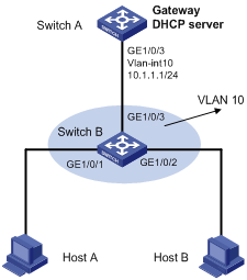
As shown in Figure 1, configure Switch A as a DHCP server and Switch B to support 802.1X. Enable ARP detection for VLAN 10 to allow only packets from valid clients to pass. Configure Host A and Host B as local 802.1X access users.
Figure 1 Network diagram for ARP detection configuration
Configuration procedure
1. Add all the ports on Switch B into VLAN 10, and configure the IP address of VLAN-interface 10 on Switch A. (Omitted)
2. Configure Switch A as a DHCP server
# Configure DHCP address pool 0
<SwitchA> system-view
[SwitchA] dhcp enable
[SwitchA] dhcp server ip-pool 0
[SwitchA-dhcp-pool-0] network 10.1.1.0 mask 255.255.255.0
3. Configure Host A and Host B as 802.1X clients (the configuration procedure is omitted) and configure them to upload IP addresses for ARP detection.
4. Configure Switch B
# Enable the 802.1X function.
<SwitchB> system-view
[SwitchB] dot1x
[SwitchB] interface gigabitethernet 1/0/1
[SwitchB-GigabitEthernet1/0/1] dot1x
[SwitchB-GigabitEthernet1/0/1] quit
[SwitchB] interface gigabitethernet 1/0/2
[SwitchB-GigabitEthernet1/0/2] dot1x
[SwitchB-GigabitEthernet1/0/2] quit
# Add local access user test.
[SwitchB] local-user test
[SwitchB-luser-test] service-type lan-access
[SwitchB-luser-test] password simple test
[SwitchB-luser-test] quit
# Enable ARP detection for VLAN 10.
[SwitchB] vlan 10
[SwitchB-vlan10] arp detection enable
# Configure the upstream port as a trusted port and the downstream ports as untrusted ports (a port is an untrusted port by default).
[SwitchB-vlan10] interface gigabitethernet 1/0/3
[SwitchB-GigabitEthernet1/0/3] arp detection trust
[SwitchB-GigabitEthernet1/0/3] quit
After the preceding configurations are complete, when ARP packets arrive at interfaces GigabitEthernet 1/0/1 and GigabitEthernet 1/0/2, they are checked against 802.1X security entries.
ARP detection configuration example II
Network requirements
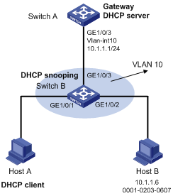
Configure Switch A as a DHCP server and enable DHCP snooping on Switch B. Configure Host A as a DHCP client. Configure Host B whose IP address is 10.1.1.6 and MAC address is 0001-0203-0607. Enable ARP detection for VLAN 10 to allow only packets from valid clients or hosts to pass.
Figure 2 Network diagram for ARP detection configuration
Configuration procedure
1. Add all the ports on Switch B to VLAN 10, and configure the IP address of VLAN-interface 10 on Switch A. (Omitted)
2. Configure Switch A as a DHCP server
# Configure DHCP address pool 0.
<SwitchA> system-view
[SwitchA] dhcp enable
[SwitchA] dhcp server ip-pool 0
[SwitchA-dhcp-pool-0] network 10.1.1.0 mask 255.255.255.0
3. Configure Host A as DHCP client, and Host B as user respectively. (Omitted)
4. Configure Switch B
# Enable DHCP snooping.
<SwitchB> system-view
[SwitchB] dhcp-snooping
[SwitchB] interface gigabitethernet 1/0/3
[SwitchB-GigabitEthernet1/0/3] dhcp-snooping trust
[SwitchB-GigabitEthernet1/0/3] quit
# Enable ARP detection for VLAN 10.
[SwitchB] vlan 10
[SwitchB-vlan10] arp detection enable
# Configure the upstream port as a trusted port and the downstream ports as untrusted ports (a port is an untrusted port by default).
[SwitchB-vlan10] interface gigabitethernet 1/0/3
[SwitchB-GigabitEthernet1/0/3] arp detection trust
[SwitchB-GigabitEthernet1/0/3] quit
# Configure a static IP source guard binding entry on interface GigabitEthernet 1/0/2.
[SwitchB] interface gigabitethernet 1/0/2
[SwitchB-GigabitEthernet1/0/2] user-bind ip-address 10.1.1.6 mac-address 0001-0203-0607 vlan 10
[SwitchB-GigabitEthernet1/0/2] quit
# Enable the checking of the MAC addresses and IP addresses of ARP packets.
[SwitchB] arp detection validate dst-mac ip src-mac
After the preceding configurations are complete, when ARP packets arrive at interfaces GigabitEthernet 1/0/1 and GigabitEthernet 1/0/2, their MAC and IP addresses are checked, and then the packets are checked against the static IP source guard binding entries and finally DHCP snooping entries.
ARP restricted forwarding configuration example
Network requirements
As shown in Figure 3, Switch A acts as a DHCP server. Host A acts as a DHCP client. Host B’s IP address is 10.1.1.6, and its MAC address is 0001-0203-0607. Port isolation configured on Switch B isolates the two hosts at Layer 2, which can communicate with the gateway Switch A. GigabitEthernet 1/0/1, GigabitEthernet 1/0/2 and GigabitEthernet 1/0/3 belong to VLAN 10. Switch B is enabled with DHCP snooping, and has ARP detection enabled in VLAN 10.
Configure Switch B to still perform port isolation on ARP broadcast requests.
Figure 3 Network diagram for ARP restricted forwarding configuration

Configuration procedure
1. Configure VLAN 10, add ports to VLAN 10, and configure the IP address of the VLAN-interface. (Omitted)
2. Configure the DHCP server on Switch A.
# Configure DHCP address pool 0.
<SwitchA> system-view
[SwitchA] dhcp enable
[SwitchA] dhcp server ip-pool 0
[SwitchA-dhcp-pool-0] network 10.1.1.0 mask 255.255.255.0
3. Configure the DHCP client on Hosts A and B. (Omitted)
4. Configure Switch B.
# Enable DHCP snooping, and configure GigabitEthernet 1/0/3 as a DHCP-trusted port.
<SwitchB> system-view
[SwitchB] dhcp-snooping
[SwitchB] interface gigabitethernet 1/0/3
[SwitchB-GigabitEthernet1/0/3] dhcp-snooping trust
[SwitchB-GigabitEthernet1/0/3] quit
# Enable ARP detection.
[SwitchB] vlan 10
[SwitchB-vlan10] arp detection enable
# Configure GigabitEthernet 1/0/3 as an ARP-trusted port.
[SwitchB-vlan10] interface gigabitethernet 1/0/3
[SwitchB-GigabitEthernet1/0/3] arp detection trust
[SwitchB-GigabitEthernet1/0/3] quit
# Configure a static IP source guard entry on interface GigabitEthernet 1/0/2.
[SwitchB] interface gigabitethernet 1/0/2
[SwitchB-GigabitEthernet1/0/2] user-bind ip-address 10.1.1.6 mac-address 0001-0203-0607 vlan 10
[SwitchB-GigabitEthernet1/0/2] quit
# Enable the checking of the MAC addresses and IP addresses of ARP packets.
[SwitchB] arp detection validate dst-mac ip src-mac
# Configure port isolation.
[SwitchB] interface gigabitethernet 1/0/1
[SwitchB-GigabitEthernet1/0/1] port-isolate enable
[SwitchB-GigabitEthernet1/0/1] quit
[SwitchB] interface gigabitethernet 1/0/2
[SwitchB-GigabitEthernet1/0/2] port-isolate enable
[SwitchB-GigabitEthernet1/0/2] quit
After the preceding configurations are complete, when ARP packets arrive at interfaces GigabitEthernet 1/0/1 and GigabitEthernet 1/0/2, their MAC and IP addresses are checked, and then the packets are checked against the static IP source guard binding entries and finally DHCP snooping entries. However, ARP broadcast requests sent from Host A can pass the check on Switch B. Port isolation fails.
# Configure ARP restricted forwarding.
[SwitchB] vlan 10
[SwitchB-vlan10] arp restricted-forwarding enable
[SwitchB-vlan10] quit
Then, Switch B forwards ARP broadcast requests from Host A to Switch A through the trusted port GigabitEthernet 1/0/3, and thus Host B cannot receive such packets. Port isolation works normally.
Configuring ARP gateway protection
Introduction
The ARP gateway protection feature, if configured on ports not connected with the gateway, can block gateway spoofing attacks.
When such a port receives an ARP packet, it checks whether the sender IP address in the packet is consistent with that of any protected gateway. If yes, it discards the packet. If not, it handles the packet normally.
Configuration procedure
Follow these steps to configure ARP gateway protection:
|
To do… |
Use the command… |
Remarks |
|
|
Enter system view |
system-view |
— |
|
|
Enter Ethernet interface view |
interface interface-type interface-number |
— |
|
|
Enable ARP gateway protection for a specified gateway |
arp filter source ip-address |
Required Disabled by default. |
|
|
|
NOTE: · You can enable ARP gateway protection for up to eight gateways on a port. · Commands arp filter source and arp filter binding cannot be both configured on a port. · If ARP gateway protection works with ARP detection, ARP gateway protection applies first. |
ARP gateway protection configuration example
Network requirements
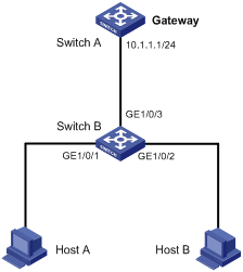
As shown in Figure 4, Host B launches gateway spoofing attacks to Switch B. As a result, traffic that Switch B intends to send to Switch A is sent to Host B.
Configure Switch B to block such attacks.
Figure 4 Network diagram for ARP gateway protection configuration
Configuration procedure
# Configure ARP gateway protection on Switch B.
<SwitchB> system-view
[SwitchB] interface gigabitethernet 1/0/1
[SwitchB-GigabitEthernet1/0/1] arp filter source 10.1.1.1
[SwitchB-GigabitEthernet1/0/1] quit
[SwitchB] interface gigabitethernet 1/0/2
[SwitchB-GigabitEthernet1/0/2] arp filter source 10.1.1.1
After the configuration is complete, Switch B will discard the ARP packets whose source IP address is that of the gateway.
Configuring ARP filtering
Introduction
To prevent gateway spoofing and user spoofing, the ARP filtering feature controls the forwarding of ARP packets on a port.
The port checks the sender IP and MAC addresses in a received ARP packet against configured ARP filtering entries. If a match is found, the packet is handled normally. If not, the packet is discarded.
Configuration procedure
Follow these steps to configure ARP filtering:
|
To do… |
Use the command… |
Remarks |
|
Enter system view |
system-view |
— |
|
Enter Ethernet interface view |
interface interface-type interface-number |
— |
|
Configure an ARP filtering entry |
arp filter binding ip-address mac-address |
Required Not configured by default. |
|
|
NOTE: · You can configure up to eight ARP filtering entries on a port. · Commands arp filter source and arp filter binding cannot be both configured on a port. · If ARP filtering works with ARP detection, ARP filtering applies first. |
ARP filtering configuration example
Network requirements
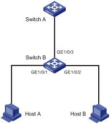
As shown in Figure 5, the IP and MAC addresses of Host A are 10.1.1.2 and 000f-e349-1233 respectively. The IP and MAC addresses of Host B are 10.1.1.3 and 000f-e349-1234 respectively.
Configure ARP filtering on GigabitEthernet 1/0/1 and GigabitEthernet 1/0/2 of Switch B to permit specific ARP packets only.
Figure 5 Network diagram for ARP filtering configuration
Configuration procedure
# Configure ARP filtering on Switch B.
<SwitchB> system-view
[SwitchB] interface gigabitethernet 1/0/1
[SwitchB-GigabitEthernet1/0/1] arp filter binding 10.1.1.2 000f-e349-1233
[SwitchB-GigabitEthernet1/0/1] quit
[SwitchB] interface gigabitethernet 1/0/2
[SwitchB-GigabitEthernet1/0/2] arp filter binding 10.1.1.9 000f-e349-1233
After the configuration is complete, GigabitEthernet 1/0/1 will permit incoming ARP packets with sender IP and MAC addresses as 10.1.1.2 and 000f-e349-1233, and discard other ARP packets. GigabitEthernet 1/0/2 will permit incoming ARP packets with sender IP and MAC addresses as 10.1.1.9 and 000f-e349-1233 and discard other ARP packets. ARP packets from Host A are permitted, but those from Host B are discarded.
