- Table of Contents
-
- 05-Comware 9 CLI-based configuration examples (AC+fit AP deployment)
- 01-HTTPS Login Configuration Examples
- 02-SSH Configuration Examples
- 03-License Management Configuration Examples
- 04-AP Association with the AC at Layer 2 Configuration Examples
- 05-AP Association with the AC at Layer 2 (IPv6) Configuration Examples
- 06-Auto AP Configuration Examples
- 07-AP Association with the AC at Layer 3 Configuration Examples
- 08-AP Association with the AC at Layer 3 (IPv6) Configuration Examples
- 09-WEP Encryption Configuration Examples
- 10-PSK Encryption Configuration Examples
- 11-WPA3-SAE PSK Encryption Configuration Examples
- 12-WLAN Access (IPv6) Configuration Examples
- 13-Policy-Based Forwarding with Dual Gateways Configuration Examples
- 14-Scheduled Configuration Deployment by AP Group Configuration Examples
- 15-Inter-AC Roaming with Static Client VLAN Allocation Configuration Examples
- 16-Service Template and Radio Binding Configuration Examples
- 17-Scheduled WLAN Access Services Configuration Examples
- 18-Local Portal Authentication Configuration Examples
- 19-HTTPS-Based Local Portal Authentication Configuration Examples
- 20-Remote Portal Authentication Configuration Examples
- 21-Local Portal Authentication through LDAP Server Configuration Examples
- 22-Local Portal Auth and SSID-based Auth Page Pushing Configuration Examples
- 23-Local Portal MAC-Trigger Authentication Configuration Examples
- 24-Portal MAC-Trigger Authentication Configuration Examples
- 25-Local Forwarding Mode and Local Portal MAC-Trigger Auth Configuration Examples
- 26-Local Portal Authentication (IPv6) Configuration Examples
- 27-Local Portal Authentication through LDAP Server (IPv6) Configuration Examples
- 28-Remote Portal Authentication (IPv6) Configuration Examples
- 29-Portal MAC-Trigger Authentication (IPv6) Configuration Example
- 30-Remote Portal Authentication with User Profile Authorization Configuration Examples
- 31-Portal Fail-Permit Configuration Examples
- 32-Local MAC Authentication Configuration Examples
- 33-Remote MAC Authentication Configuration Examples
- 34-Transparent Auth Through Remote MAC and Portal Auth Configuration Examples
- 35-Remote AP, Remote Portal, and MAC-Trigger Authentication Configuration Examples
- 36-MAC Authentication with Guest VLAN Assignment Configuration Examples
- 37-MAC Authentication with Guest VLAN Assignment (IPv6) Configuration Examples
- 38-Local MAC-And-802.1X Authentication Configuration Examples
- 39-Local 802.1X Authentication Configuration Examples
- 40-Local RADIUS-Based 802.1X Authentication in EAP Relay Mode Configuration Examples
- 41-Remote 802.1X Authentication Configuration Examples
- 42-Remote 802.1X Authentication (IPv6) Configuration Examples
- 43-Remote 802.1X Authentication in WPA3-Enterprise Mode Configuration Examples
- 44-802.1X Auth with ACL Assignment Through IMC Server Configuration Examples
- 45-802.1X Auth with User Profile Assignment Through IMC Server Configuration Examples
- 46-EAD Authentication Configuration Examples
- 47-EAD Authentication (IPv6) Configuration Examples
- 48-Local Forwarding Mode and Local Portal Authentication Configuration Examples
- 49-Local Forwarding Mode Direct Portal Authentication Configuration Examples
- 50-Local Forwarding Mode Direct Portal Authentication (IPv6) Configuration Examples
- 51-Local Forwarding Configuration Examples
- 52-Wired Port Local Forwarding through Wireless Terminator Configuration Examples
- 53-Remote AP Configuration Examples
- 54-Downlink VLAN Management for Fit-Mode APs Configuration Examples
- 55-WIPS Configuration Examples
- 56-WIPS Countermeasures Against All SSIDs Configuration Examples
- 57-IP Source Guard (IPv4) Configuration Examples
- 58-IP Source Guard (IPv6) Configuration Examples
- 59-Dual-Link Backup Configuration Examples
- 60-OAuth-Based Portal MAC-Trigger Auth on a Local-Forwarding Dual-Link Backup Configuration Examples
- 61-Dual-Link Backup OAuth-Based Portal Authentication in Local Forwarding Configuration Examples
- 62-Dual-Link Backup Remote Portal MAC-Trigger Authentication in Local Forwarding Configuration Examples
- 63-Dual-Link Backup Remote Portal and Transparent MAC Auth in Local Forwarding Configuration Examples
- 64-Dual-Link Backup Remote Portal Authentication in Local Forwarding Configuration Examples
- 65-Dual-Link Backup Remote Portal and Transparent MAC Auth in Centralized Forwarding Configuration Examples
- 66-Dual-Link Backup Remote Portal Authentication in Centralized Forwarding Configuration Examples
- 67-Dual-Link Backup Lightweight Portal Authentication in Centralized Forwarding Configuration Examples
- 68-Dual-Link Backup OAuth-Based Portal Authentication in Centralized Forwarding Configuration Examples
- 69-Dual-Link Backup Remote Portal MAC-Trigger Auth in Centralized Forwarding Configuration Examples
- 70-Remote 802.1X Authentication on a Dual-Link AC Backup Network Configuration Examples
- 71-Remote MAC Authentication on a Dual-Link AC Backup Network Configuration Examples
- 72-WLAN Probe Configuration Examples
- 73-Multicast Optimization Configuration Examples
- 74-Client Rate Limiting Configuration Examples
- 75-Inter-AC Roaming Configuration Examples
- 76-Inter-AC Roaming (IPv6) Configuration Examples
- 77-Inter-AC Roaming in Local Forwarding Mode Configuration Examples
- 78-H3C Access Controllers Cooperative Roaming for 802.11v Clients Configuration Examples
- 79-WLAN Load Balancing Configuration Examples
- 80-Static Blacklist Configuration Examples
- 81-Client Quantity Control Configuration Examples
- 82-AP License Synchronization Configuration Examples
- 83-BLE Module iBeacon Transmission Configuration Examples
- 84-Medical RFID Tag Management Configuration Examples
- 85-iBeacon Management Configuration Examples
- 86-Mesh Link Establishment Between a Fit AP and a Fat AP Configuration Examples
- 87-Mesh Link Establishment Between Fit APs Configuration Examples
- 88-Auto-DFS and Auto-TPC Configuration Examples
- 89-AP Image Downloading Configuration Examples
- 90-Dual-Uplink Interfaces Configuration Guide
- 91-Internal-to-External Access Through NAT Configuration Examples
- 92-Layer 2 Static Aggregation Configuration Examples
- 93-Layer 2 Multicast Configuration Examples
- 94-Static VLAN Allocation Configuration Examples
- 95-URL Redirection Configuration Examples
- 96-IPv6 URL Redirection Configuration Examples
- Related Documents
-
| Title | Size | Download |
|---|---|---|
| 94-Static VLAN Allocation Configuration Examples | 121.80 KB |
|
|
|
H3C Access Controllers |
|
Static VLAN Allocation |
|
Configuration Examples |
|
|
Copyright © 2023 New H3C Technologies Co., Ltd. All rights reserved.
No part of this manual may be reproduced or transmitted in any form or by any means without prior written consent of New H3C Technologies Co., Ltd.
Except for the trademarks of New H3C Technologies Co., Ltd., any trademarks that may be mentioned in this document are the property of their respective owners.
The information in this document is subject to change without notice.
Introduction
The following information provides an example for configuring static VLAN allocation to allow clients to evenly join VLANs in different VLAN groups.
Prerequisites
The following information applies to Comware-based access controllers and access points. Procedures and information in the examples might be slightly different depending on the software or hardware version of the access controllers and access points.
The configuration examples were created and verified in a lab environment, and all the devices were started with the factory default configuration. When you are working on a live network, make sure you understand the potential impact of every command on your network.
The following information is provided based on the assumption that you have basic knowledge of VLAN group.
Example: Configuring static VLAN allocation
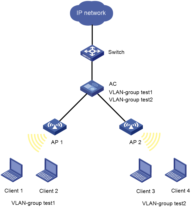
Network configuration
As shown in Figure 1, the switch acts as the DHCP server to assign IP addresses to the APs and clients. Configure two VLAN groups on the AC for the clients to evenly join VLANs in different VLAN groups.
|
Device |
Interface |
IP address |
Device |
Interface |
IP address |
|
AC |
Vlan-int2 |
192.12.0.2/16 |
Switch |
Vlan-int2 |
192.12.0.1/16 |
|
|
Vlan-int10 |
192.10.0.2/16 |
|
Vlan-int10 |
192.10.0.1/16 |
|
|
Vlan-int20 |
192.20.0.2/16 |
|
Vlan-int20 |
192.20.0.1/16 |
|
|
Vlan-int30 |
192.30.0.2/16 |
|
Vlan-int30 |
192.30.0.1/16 |
|
|
Vlan-int40 |
192.40.0.2/16 |
|
Vlan-int40 |
192.40.0.1/16 |
Procedures
Configuring the AC
1. Configure interfaces on the AC:
# Create VLAN 2 and VLAN-interface 2, and assign an IP address to the VLAN interface. The AC will use this IP address to establish a CAPWAP tunnel with the AP.
<AC> system-view
[AC] vlan 2
[AC-vlan2] quit
[AC] interface vlan-interface 2
[AC-Vlan-interface2] ip address 192.12.0.2 16
[AC-Vlan-interface2] quit
# Create VLAN 10 and VLAN-interface 10, and assign an IP address to the VLAN interface. VLAN 10 will be used for client access.
[AC] vlan 10
[AC-vlan10] quit
[AC] interface vlan-interface 10
[AC-Vlan-interface10] ip address 192.10.0.2 16
[AC-Vlan-interface10] quit
# Create VLAN 20 and VLAN-interface 20 and assign an IP address to the VLAN interface. VLAN 20 will be used for client access.
[AC] vlan 20
[AC-vlan20] quit
[AC] interface vlan-interface 20
[AC-Vlan-interface20] ip address 192.20.0.2 16
[AC-Vlan-interface20] quit
# Create VLAN 30 and VLAN-interface 30, and assign an IP address to the VLAN interface. VLAN 10 will be used for client access.
[AC] vlan 30
[AC-vlan30] quit
[AC] interface vlan-interface 30
[AC-Vlan-interface30] ip address 192.30.0.2 16
[AC-Vlan-interface30] quit
# Create VLAN 40 and VLAN-interface 40, and assign an IP address to the VLAN interface. VLAN 10 will be used for client access.
[AC] vlan 40
[AC-vlan40] quit
[AC] interface vlan-interface 40
[AC-Vlan-interface40] ip address 192.40.0.2 16
[AC-Vlan-interface40] quit
# Specify GigabitEthernet 1/0/1 that connects the AC to the switch as a trunk port, and assign it to VLANs 2, 10, 20, 30, and 40.
[AC] interface gigabitethernet 1/0/1
[AC-GigabitEthernet1/0/1] port link-type trunk
[AC-GigabitEthernet1/0/1] port trunk permit vlan 2 10 20 30 40
[AC-GigabitEthernet1/0/1] quit
# Specify GigabitEthernet 1/0/2 that connects the AC to the AP as a trunk port, and assign it to VLAN 2.
[AC] interface gigabitethernet 1/0/2
[AC-GigabitEthernet1/0/2] port link-type trunk
[AC-GigabitEthernet1/0/2] port trunk permit vlan 2
[AC-GigabitEthernet1/0/2] quit
2. Configure VLAN groups:
# Create VLAN-group test1 and add VLANs 10 and 20 to the group.
[AC] vlan-group test1
[AC-vlan-group-test1] vlan-list 10 20
# Create VLAN-group test2 and add VLANs 30 and 40 to the group.
[AC] vlan-group test2
[AC-vlan-group-test2] vlan-list 30 40
3. Configure a wireless service:
# Create service template 1 and enter its view.
[AC] wlan service-template 1
# Configure the SSID as service.
[AC-wlan-st-1] ssid service
# Set the authentication and key management mode to PSK, and configure simple character string of 12345678 as the PSK.
[AC-wlan-st-1] akm mode psk
[AC-wlan-st-1] preshared-key pass-phrase simple 12345678
# Set the AES-CCMP cipher suite for frame encryption, and enable the RSN IE in beacon and probe responses.
[AC-wlan-st-1] cipher-suite ccmp
[AC-wlan-st-1] security-ie rsn
# Enable the AC to forward client data traffic. (Skip this step is the AC forwards client data traffic by default.)
[AC-wlan-st-1] client forwarding-location ac
# Set the VLAN allocation method to static.
[AC-wlan-st-1] client vlan-alloc static
|
|
NOTE: If dynamic VLAN allocation is used, clients cannot change IP addresses proactively, which might cause disconnection from the WLAN. To avoid unexpected disconnection, set the VLAN allocation method to static. |
# Enable the service template.
[AC-wlan-st-1] service-template enable
[AC-wlan-st-1] quit
4. Configure AP settings:
|
|
NOTE: On a large-scaled network, as a best practice, configuring settings in AP groups. |
# Create a manual AP named ap1, and specify the AP model and serial ID.
[AC] wlan ap ap1 model WA6320
[AC-wlan-ap-ap1] serial-id 219801A28N819CE0002T
[AC-wlan-ap-ap1] quit
# Create a manual AP named ap2, and specify the AP model and serial ID.
[AC] wlan ap ap2 model WA6320
[AC-wlan-ap-ap2] serial-id 219801A28N819CE00033
[AC-wlan-ap-ap2] quit
# Create AP group group1, and create an AP grouping rule by AP names.
[AC] wlan ap-group group1
[AC-wlan-ap-group-group1] ap ap1
# Enter radio view of radio 1 in AP group group1, bind service template 1 to radio 1, and specify VLAN group test1.
[AC-wlan-ap-group-group1] ap-model WA6320
[AC-wlan-ap-group-group1-ap-model-WA6320] radio 1
[AC-wlan-ap-group-group1-ap-model-WA6320-radio-1] service-template 1 vlan-group test1
# Enable radio 1.
[AC-wlan-ap-group-group1-ap-model-WA6320-radio-1] radio enable
[AC-wlan-ap-group-group1-ap-model-WA6320-radio-1] quit
[AC-wlan-ap-group-group1-ap-model-WA6320] quit
[AC-wlan-ap-group-group1] quit
# Create AP group group2, and create an AP grouping rule by AP names.
[AC] wlan ap-group group2
[AC-wlan-ap-group-group2] ap ap2
# Enter radio view of radio 1 in AP group group2, bind service template 1 to radio 1, and specify VLAN group test2.
[AC-wlan-ap-group-group2] ap-model WA6320
[AC-wlan-ap-group-group2-ap-model-WA6320] radio 1
[AC-wlan-ap-group-group2-ap-model-WA6320-radio-1] service-template 1 vlan-group test2
# Enable radio 1.
[AC-wlan-ap-group-group2-ap-model-WA6320-radio-1] radio enable
[AC-wlan-ap-group-group2-ap-model-WA6320-radio-1] quit
[AC-wlan-ap-group-group2-ap-model-WA6320] quit
[AC-wlan-ap-group-group2] quit
Configure the switch
1. Configure switch interfaces:
# Create VLAN 2 and assign an IP address to VLAN-interface 2.
<Switch> system-view
[Switch] vlan 2
[Switch-vlan2] quit
[Switch] interface vlan-interface 2
[Switch-Vlan-interface2] ip address 192.12.0.1 16
[Switch-Vlan-interface2] quit
# Create VLAN 10 and assign an IP address to VLAN-interface 10.
[Switch] vlan 10
[Switch-vlan10] quit
[Switch] interface vlan-interface 10
[Switch-Vlan-interface10] ip address 192.10.0.1 16
[Switch-Vlan-interface10] quit
# Create VLAN 20 and assign an IP address to VLAN-interface 20.
[Switch] vlan 20
[Switch-vlan20] quit
[Switch] interface vlan-interface 20
[Switch-Vlan-interface20] ip address 192.20.0.1 16
[Switch-Vlan-interface20] quit
# Create VLAN 30 and assign an IP address to VLAN-interface 30.
[Switch] vlan 30
[Switch-vlan30] quit
[Switch] interface vlan-interface 30
[Switch-Vlan-interface30] ip address 192.30.0.1 16
[Switch-Vlan-interface30] quit
# Create VLAN 40 and assign an IP address to VLAN-interface 40.
[Switch] vlan 40
[Switch-vlan40] quit
[Switch] interface vlan-interface 40
[Switch-Vlan-interface40] ip address 192.40.0.1 16
[Switch-Vlan-interface40] quit
# Configure GigabitEthernet 1/0/2 that connects the switch to the AC as a trunk port, and assign the access port to VLAN 2, 10, 20, 30, and 40.
[Switch] interface gigabitethernet 1/0/2
[Switch-GigabitEthernet1/0/2] port link-type trunk
[Switch-GigabitEthernet1/0/2] port trunk permit vlan 2 10 20 30 40
[Switch-GigabitEthernet1/0/2] quit
2. Configure the DHCP server:
# Enable DHCP.
[Switch] dhcp enable
# Create DHCP address pool vlan2, specify primary subnet 192.2.0.0/16, and specify the gateway address as 192.2.0.1. The switch will use this pool to assign addresses to the AP.
[Switch] dhcp server ip-pool vlan2
[Switch-dhcp-pool-vlan2] network 192.12.0.0 mask 255.255.0.0
[Switch-dhcp-pool-vlan2] gateway-list 192.12.0.1
[Switch-dhcp-pool-vlan2] quit
# Create DHCP address pool vlan10, specify primary subnet 192.10.0.0/16, specify the gateway address as 192.10.0.1, and specify a DNS server The switch will use this pool to assign addresses to clients. In this example, the gateway acts as the DNS server.
[Switch] dhcp server ip-pool vlan10
[Switch-dhcp-pool-vlan10] network 192.10.0.0 mask 255.255.0.0
[Switch-dhcp-pool-vlan10] gateway-list 192.10.0.1
[Switch-dhcp-pool-vlan10] dns-list 192.10.0.1
[Switch-dhcp-pool-vlan10] quit
# Create DHCP address pool vlan20, specify primary subnet 192.20.0.0/16, specify the gateway address as 192.20.0.1, and specify a DNS server The switch will use this pool to assign addresses to clients. In this example, the gateway acts as the DNS server.
[Switch] dhcp server ip-pool vlan20
[Switch-dhcp-pool-vlan20] network 192.20.0.0 mask 255.255.0.0
[Switch-dhcp-pool-vlan20] gateway-list 192.20.0.1
[Switch-dhcp-pool-vlan20] dns-list 192.20.0.1
[Switch-dhcp-pool-vlan20] quit
# Create DHCP address pool vlan30, specify primary subnet 192.30.0.0/16, specify the gateway address as 192.30.0.1, and specify a DNS server The switch will use this pool to assign addresses to clients. In this example, the gateway acts as the DNS server.
[Switch] dhcp server ip-pool vlan30
[Switch-dhcp-pool-vlan30] network 192.30.0.0 mask 255.255.0.0
[Switch-dhcp-pool-vlan30] gateway-list 192.30.0.1
[Switch-dhcp-pool-vlan30] dns-list 192.30.0.1
[Switch-dhcp-pool-vlan30] quit
# Create DHCP address pool vlan40, specify primary subnet 192.40.0.0/16, specify the gateway address as 192.40.0.1, and specify a DNS server The switch will use this pool to assign addresses to clients. In this example, the gateway acts as the DNS server.
[Switch] dhcp server ip-pool vlan40
[Switch-dhcp-pool-vlan40] network 192.40.0.0 mask 255.255.0.0
[Switch-dhcp-pool-vlan40] gateway-list 192.40.0.1
[Switch-dhcp-pool-vlan40] dns-list 192.40.0.1
[Switch-dhcp-pool-vlan40] quit
Verifying the configuration
# Make client 1 and client 2 come online from SSID service provided by AP 1.
# Verify that the two clients are assigned to different VLANs in VLAN group test1.
[AC]display wlan client
Total number of clients: 2
MAC address User name AP name R IP address VLAN
90f0-528e-0871 N/A ap1 1 192.10.0.3 10
961b-66ea-72c5 N/A ap1 1 192.20.0.3 20
Configuration files
#
vlan 2
#
vlan 10
#
vlan 20
#
vlan 30
#
vlan 40
#
vlan-group test1
vlan-list 10 20
#
vlan-group test2
vlan-list 30 40
#
wlan service-template 1
ssid service
client forwarding-location ac
akm mode psk
preshared-key pass-phrase cipher $c$3$N//5BVbsOqdBTxi+7MJZKT6Zqh5MAmYs2ZzM
cipher-suite ccmp
security-ie rsn
client vlan-alloc static
service-template enable
#
interface Vlan-interface2
ip address 192.12.0.2 255.255.0.0
#
interface Vlan-interface10
ip address 192.10.0.2 255.255.0.0
#
interface Vlan-interface20
ip address 192.20.0.2 255.255.0.0
#
interface Vlan-interface30
ip address 192.30.0.2 255.255.0.0
#
interface Vlan-interface40
ip address 192.40.0.2 255.255.0.0
#
interface GigabitEthernet1/0/1
port link-type trunk
port trunk permit vlan 2 10 20 30 40
#
interface GigabitEthernet1/0/2
port link-type trunk
port trunk permit vlan 2
#
wlan ap-group group1
ap ap1
ap-model WA6320
radio 1
service-template 1 vlan-group test1
radio enable
#
wlan ap-group group2
ap ap2
ap-model WA6320
radio 1
service-template 1 vlan-group test2
radio enable
#
wlan ap ap1 model WA6320
serial-id 219801A28N819CE0002T
#
wlan ap ap2 model WA6320
serial-id 219801A28N819CE00033
· Switch:
#
dhcp enable
#
vlan 2
#
vlan 10
#
vlan 20
#
vlan 30
#
vlan 40
#
dhcp server ip-pool vlan2
gateway-list 192.12.0.1
network 192.12.0.0 mask 255.255.0.0
#
dhcp server ip-pool vlan10
gateway-list 192.10.0.1
network 192.10.0.0 mask 255.255.0.0
dns-list 192.10.0.1
#
dhcp server ip-pool vlan20
gateway-list 192.20.0.1
network 192.20.0.0 mask 255.255.0.0
dns-list 192.20.0.1
#
dhcp server ip-pool vlan30
gateway-list 192.30.0.1
network 192.30.0.0 mask 255.255.0.0
dns-list 192.30.0.1
#
dhcp server ip-pool vlan40
gateway-list 192.40.0.1
network 192.40.0.0 mask 255.255.0.0
dns-list 192.40.0.1
#
interface Vlan-interface2
ip address 192.12.0.1 255.255.0.0
#
interface Vlan-interface10
ip address 192.10.0.1 255.255.0.0
#
interface Vlan-interface20
ip address 192.20.0.1 255.255.0.0
#
interface Vlan-interface30
ip address 192.30.0.1 255.255.0.0
#
interface Vlan-interface40
ip address 192.40.0.1 255.255.0.0
#
interface GigabitEthernet1/0/2
port link-type trunk
port trunk permit vlan 2 10 20 30 40
Related documentation
· AP Management Command Reference in H3C Access Controllers Command References
· AP Management Configuration Guide in H3C Access Controllers Configuration Guides
· User Access and Authentication Command Reference in H3C Access Controllers Command References
· User Access and Authentication Configuration Guide in H3C Access Controllers Configuration Guides
· WLAN Access Command Reference in H3C Access Controllers Command References
· WLAN Access Configuration Guide in H3C Access Controllers Configuration Guides
