- Table of Contents
-
- 04-Layer 3 Configuration Guide
- 00-Preface
- 01-ARP Configuration
- 02-IP Addressing Configuration
- 03-DHCP Configuration
- 04-DHCPv6 Configuration
- 05-DNS Configuration
- 06-IPv6 DNS Configuration
- 07-NAT Configuration
- 08-Adjacency Table Configuration
- 09-Flow Classification Configuration
- 10-IPv6 Basics Configuration
- 11-IP Performance Optimization Configuration
- 12-IP Routing Basics
- 13-Static Routing Configuration
- 14-IPv6 Static Routing Configuration
- 15-GRE Configuration
- 16-RIP Configuration
- 17-RIPng Configuration
- 18-Policy-Based Routing Configuration
- Related Documents
-
| Title | Size | Download |
|---|---|---|
| 18-Policy-Based Routing Configuration | 170.04 KB |
Configuring policy-based routing
Configuring match criteria for a node
Configuring actions for a node
Displaying and maintaining PBR
Configuring local PBR based on packet type
Configuring interface PBR based on packet type
Configuring interface PBR based on packet length
Configuring local PBR to specify output interface and next hop
Configuring policy-based routing
Overview
Different from destination-based routing, policy-based routing (PBR) uses user-defined policies to route packets based on the source address, packet length, and other criteria. A policy can specify the output interface, next hop, default output interface, default next hop, and other parameters for packets that match specific criteria such as ACLs or have specific lengths.
A device uses PBR to forward matching packets and uses the routing table to forward other packets. If PBR is not configured, a device uses the routing table to forward packets.
PBR falls into local PBR and interface PBR.
· Local PBR guides the forwarding of locally generated packets, such as the ICMP packets generated by using the ping command.
· Interface PBR guides the forwarding of packets received on an interface only.
Policy
A policy comprises match criteria and actions to be taken on the matching packets. A policy can comprise one or multiple nodes. The following describes information about nodes:
· Each node is identified by a node number. A smaller node number has a higher priority.
· A node comprises if-match and apply clauses. An if-match clause specifies a match criterion, and an apply clause specifies an action.
· A node has a match mode of permit or deny.
A policy matches nodes in priority order against packets. If a packet satisfies the match criteria on a node, it is processed by the action on the node. Otherwise, it goes to the next node for a match. If the packet does not match the criteria on any node, it is forwarded according to the routing table.
if-match clause
PBR supports the following types of if-match clauses:
· if-match acl—Sets an ACL match criteria.
· if-match packet-length—Sets a packet length match criterion.
You can specify multiple if-match clauses for a node, but only one if-match clause can be specified for each type at most. To match a node, a packet must satisfy all the if-match clauses of the node.
apply clause
PBR supports the following types of apply clauses, as shown in Table 1. You can specify multiple apply clauses for a node, but some of them might not be executed.
Table 1 Priorities and meanings of apply clauses
|
Clause |
Meaning |
Priority |
|
apply ip-df zero |
Sets the DF (Don't Fragment) bit in the IP header to 0, which means the packet can be fragmented. |
This clause is always executed. |
|
apply ip-precedence |
Sets an IP precedence. |
This clause is always executed. |
|
apply output-interface and apply ip-address next-hop |
Sets the output interface and sets the next hop. |
The apply output-interface clause takes precedence over the apply ip-address next-hop clause. Only the apply output-interface clause is executed when both are configured. |
|
apply output-interface ip-address next-hop dhcpc |
Sets the output interface and next hop (the next hop address is the gateway address learned through DHCP). |
For a point to point (P2P) link, the next hop address is the peer address, so you only need to specify the output interface by using the apply output-interface command. For a non-P2P link, specify both the output interface and the next hop. If the output interface obtains an IP address through DHCP, you can use the apply output-interfac ip-address next-hop dhcpc command to specify the gateway address learned through DHCP as the next hop. |
|
apply default output-interface and apply ip-address default next-hop |
Sets the default output interface and sets the default next hop. |
The apply default output-interface clause takes precedence over the apply ip-address default next-hop clause. Only the apply default output-interface clause is executed when both are configured. They take effect only when no output interface or next hop is set or the output interface and next hop are invalid, and the packet does not match any route in the routing table. |
Relationship between the match mode and clauses on a node
|
Does a packet match all the if-match clauses on the node? |
Match mode |
|
|
permit |
deny |
|
|
Yes |
PBR executes the apply clause on the node. |
The packet is forwarded according to the routing table. |
|
No |
PBR matches the packet against the next node. |
PBR matches the packet against the next node. |
All packets can match a node where no if-match clauses are configured.
If a permit-mode node has no apply clause, packets matching all the if-match clauses of the node are forwarded according to the routing table.
If a node has no if-match or apply clauses configured, all packets can match the node and are forwarded according to the routing table.
PBR and track
You can use track to monitor the output interface, default output interface, next hop, and default next hop for PBR so that PBR can discover link failures faster. PBR takes effect when the status of the associated track entry is positive or invalid.
For more information about track-PBR collaboration, see High Availability Configuration Guide.
PBR configuration task list
|
Task |
Remarks |
|
|
Required. |
||
|
Required. Perform one of the tasks. |
||
Configuring a policy
Creating a node
|
Step |
Command |
|
1. Enter system view. |
system-view |
|
2. Create a node for a policy and enter policy node view. |
policy-based-route policy-name [ deny | permit ] node node-number |
Configuring match criteria for a node
The if-match acl clause uses the specified ACL to match packets if the match mode is configured as permit. If the specified ACL does not exist or the match mode is configured as deny, no packet can match the criterion.
To configure match criteria for a node:
|
Step |
Command |
Remarks |
|
1. Enter system view. |
system-view |
N/A |
|
2. Enter policy node view. |
policy-based-route policy-name [ deny | permit ] node node-number |
N/A |
|
3. Configure an ACL match criterion. |
if-match acl acl-number |
Optional. |
|
4. Configure a packet length match criterion. |
if-match packet-length min-len max-len |
Optional. |
Configuring actions for a node
|
Step |
Command |
Remarks |
|
1. Enter system view. |
system-view |
N/A |
|
2. Enter policy node view. |
policy-based-route policy-name [ deny | permit ] node node-number |
N/A |
|
3. Set the DF bit in the IP header to 0, which means the packet can be fragmented. |
apply ip-df zero |
Optional. |
|
4. Set an IP precedence. |
apply ip-precedence value |
Optional. |
|
5. Set output interfaces. |
apply output-interface interface-type interface-number [ track track-entry-number ] [ interface-type interface-number [ track track-entry-number ] ] |
Optional. You can specify a maximum of two output interfaces to achieve load sharing. |
|
6. Set the output interface and next hop (the next hop address is the gateway address learned through DHCP). |
apply output-interface interface-type interface-number ip-address next-hop dhcpc |
Optional. |
|
7. Set next hops. |
apply ip-address next-hop ip-address [ direct ] [ track track-entry-number ] [ ip-address [ direct ] [ track track-entry-number ] ] |
Optional. You can specify a maximum of two next hops to achieve load sharing. |
|
8. Set default output interfaces. |
apply default output-interface interface-type interface-number [ track track-entry-number ] [ interface-type interface-number [ track track-entry-number ] ] |
Optional. You can specify a maximum of two default output interfaces to achieve load sharing. |
|
9. Set default next hops. |
apply ip-address default next-hop ip-address [ track track-entry-number ] [ ip-address [ track track-entry-number ] ] |
Optional. You can specify a maximum of two default next hops to achieve load sharing. |
Configuring PBR
Configuring local PBR
Configure PBR by applying a policy locally. PBR uses the policy to guide the forwarding of locally generated packets.
You can apply only one policy locally. If you perform the ip local policy-based-route command multiple times, only the last specified policy takes effect.
If the specified policy does not exist, the local PBR configuration succeeds, but it does not take effect until the policy is created.
Do not configure local PBR unless required.
To configure local PBR:
|
Step |
Command |
Remarks |
|
1. Enter system view. |
system-view |
N/A |
|
2. Apply a policy locally. |
ip local policy-based-route policy-name |
Not applied by default. |
Configuring interface PBR
Configure PBR by applying a policy on an interface. PBR uses the policy to guide the forwarding of packets received on the interface.
You can apply only one policy to an interface. If you perform the ip policy-based-route command multiple times, only the last specified policy takes effect.
If the specified policy does not exist, the interface PBR configuration succeeds, but it does not take effect until the policy is created.
You can apply the same policy on multiple interfaces.
To configure interface PBR:
|
Step |
Command |
Remarks |
|
1. Enter system view. |
system-view |
N/A |
|
2. Enter interface view. |
interface interface-type interface-number |
N/A |
|
3. Apply a policy on the interface. |
ip policy-based-route policy-name |
Not applied by default. |
Displaying and maintaining PBR
|
Command |
Remarks |
|
|
Display PBR configuration for a policy. |
display policy-based-route [ policy-name ] [ | { begin | exclude | include } regular-expression ] |
Available in any view. |
|
Display information about local PBR and interface PBR. |
display ip policy-based-route [ | { begin | exclude | include } regular-expression ] |
Available in any view. |
|
Display PBR configuration. |
display ip policy-based-route setup { interface interface-type interface-number | local | policy-name } [ | { begin | exclude | include } regular-expression ] |
Available in any view. |
|
Display PBR statistics. |
display ip policy-based-route statistics { interface interface-type interface-number | local } [ | { begin | exclude | include } regular-expression ] |
Available in any view. |
|
Clear PBR statistics. |
reset policy-based-route statistics [ policy-name ] |
Available in user view. |
PBR configuration examples
Configuring local PBR based on packet type
Network requirements
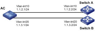
As shown in Figure 1, configure local PBR on the AC to forward all locally generated TCP packets to the next hop 1.1.2.2. The AC forwards other packets according to the routing table.
Configuration procedure
1. Configure the AC:
# Create VLAN 10, and assign the IP address 1.1.2.1/24 to VLAN-interface 10.
<AC> system-view
[AC] vlan 10
[AC-vlan10] quit
[AC] interface vlan-interface 10
[AC-Vlan-interface10] ip address 1.1.2.1 24
[AC-Vlan-interface10] quit
# Create VLAN 20, and assign the IP address 1.1.3.1/24 to VLAN-interface 20.
[AC] vlan 20
[AC-vlan20] quit
[AC] interface vlan-interface 20
[AC-Vlan-interface20] ip address 1.1.3.1 24
[AC-Vlan-interface20] quit
# Configure ACL 3101 to match TCP packets.
[AC] acl number 3101
[AC-acl-adv-3101] rule permit tcp
[AC-acl-adv-3101] quit
# Configure Node 5 for policy aaa to forward TCP packets to next hop 1.1.2.2.
[AC] policy-based-route aaa permit node 5
[AC-pbr-aaa-5] if-match acl 3101
[AC-pbr-aaa-5] apply ip-address next-hop 1.1.2.2
[AC-pbr-aaa-5] quit
# Configure local PBR by applying policy aaa to the AC.
[AC] ip local policy-based-route aaa
2. Configure Switch A:
# Create VLAN 10, and assign the IP address 1.1.2.2/24 to VLAN-interface 10.
<SwitchA> system-view
[SwitchA] vlan 10
[SwitchA-vlan10] quit
[SwitchA] interface vlan-interface 10
[SwitchA-Vlan-interface10] ip address 1.1.2.2 24
[SwitchA-Vlan-interface10] quit
3. Configure Switch B:
# Create VLAN 20, and assign the IP address 1.1.3.2/24 to VLAN-interface 20.
<SwitchB> system-view
[SwitchB] vlan 20
[SwitchB-vlan20] quit
[SwitchB] interface vlan-interface 20
[SwitchB-Vlan-interface20] ip address 1.1.3.2 24
[SwitchB-Vlan-interface20] quit
4. Verify the configuration:
# Telnet to Switch A on the AC. The operation succeeds.
# Telnet to Switch B on the AC. The operation fails.
# Ping Switch B from the AC. The operation succeeds.
Telnet uses TCP, and ping uses ICMP. The results show the following:
? All TCP packets sent from the AC are forwarded to the next hop 1.1.2.2.
? Other packets are forwarded through VLAN-interface 20.
? The local PBR configuration is effective.
Configuring interface PBR based on packet type
Network requirements
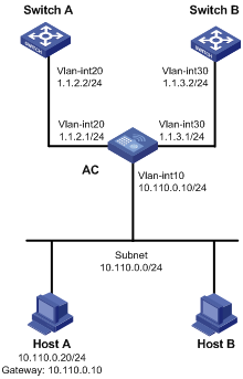
As shown in Figure 2, configure interface PBR on the AC to forward all TCP packets received on VLAN-interface 10 to the next hop 1.1.2.2. The AC forwards other packets according to the routing table.
Configuration procedure
1. Configure the AC:
# Create VLAN 10, and assign the IP address 10.110.0.10/24 to VLAN-interface 10.
<AC> system-view
[AC] vlan 10
[AC-vlan10] quit
[AC] interface vlan-interface 10
[AC-Vlan-interface10] ip address 10.110.0.10 24
[AC-Vlan-interface10] quit
# Create VLAN 20, and assign the IP address 1.1.2.1/24 to VLAN-interface 20.
<AC> system-view
[AC] vlan 20
[AC-vlan20] quit
[AC] interface vlan-interface 20
[AC-Vlan-interface20] ip address 1.1.2.1 24
[AC-Vlan-interface20] quit
# Create VLAN 30, and assign the IP address 1.1.3.1/24 to VLAN-interface 30.
<AC> system-view
[AC] vlan 30
[AC-vlan30] quit
[AC] interface vlan-interface 30
[AC-Vlan-interface30] ip address 1.1.3.1 24
[AC-Vlan-interface30] quit
# Configure ACL 3101 to match TCP packets.
[AC] acl number 3101
[AC-acl-adv-3101] rule permit tcp
[AC-acl-adv-3101] quit
# Configure Node 5 for policy aaa to forward TCP packets to next hop 1.1.2.2.
[AC] policy-based-route aaa permit node 5
[AC-pbr-aaa-5] if-match acl 3101
[AC-pbr-aaa-5] apply ip-address next-hop 1.1.2.2
[AC-pbr-aaa-5] quit
# Configure interface PBR by applying the policy aaa to VLAN-interface 10.
[AC] interface vlan-interface10
[AC-Vlan-interface10] ip policy-based-route aaa
[AC-Vlan-interface10] quit
2. Configure Switch A:
# Create VLAN 20, and assign the IP address 1.1.2.2/24 to VLAN-interface 20.
<SwitchA> system-view
[SwitchA] vlan 20
[SwitchA-vlan20] quit
[SwitchA] interface vlan-interface 20
[SwitchA-Vlan-interface20] ip address 1.1.2.2 24
[SwitchA-Vlan-interface20] quit
# Configure a static route to subnet 10.110.0.0/24.
[SwitchA] ip route-static 10.110.0.0 24 1.1.2.1
3. Configure Switch B:
# Create VLAN 30, and assign the IP address 1.1.3.2/24 to VLAN-interface 30.
<SwitchB> system-view
[SwitchB] vlan 30
[SwitchB-vlan30] quit
[SwitchB] interface vlan-interface 30
[SwitchB-Vlan-interface30] ip address 1.1.3.2 24
[SwitchB-Vlan-interface30] quit
# Configure a static route to subnet 10.110.0.0/24.
[SwitchB] ip route-static 10.110.0.0 24 1.1.3.1
4. Verify the configuration:
# Configure the IP address 10.110.0.20/24 for Host A, and specify its gateway address as 10.110.0.10.
# On Host A, Telnet to Switch A that is directly connected to the AC. The operation succeeds.
# On Host A, Telnet to Switch B that is directly connected to the AC. The operation fails.
# Ping Switch B from Host A. The operation succeeds.
Telnet uses TCP and ping uses ICMP. The results show the following:
? All TCP packets received on VLAN-interface 10 of the AC are forwarded to the next hop 1.1.2.2.
? Other packets are forwarded through VLAN-interface 30.
? The interface PBR configuration is effective.
Configuring interface PBR based on packet length
Network requirements
As shown in Figure 3, configure interface PBR to guide the forwarding of packets received on VLAN-interface 10 of the AC as follows:
· Forwards packets with a length of 64 to 100 bytes to the next hop 150.1.1.2/24.
· Forwards packets with a length of 101 to 1000 to the next hop 151.1.1.2/24.
All other packets are forwarded according to the routing table.

Configuration procedure
1. Configure the AC:
# Create VLAN 10, and assign the IP address 150.1.1.1/24 to VLAN-interface 10.
<AC> system-view
[AC] vlan 10
[AC-vlan10] quit
[AC] interface vlan-interface 10
[AC-Vlan-interface10] ip address 150.1.1.1 24
[AC-Vlan-interface10] quit
# Create VLAN 20, and assign the IP address 151.1.1.1/24 to VLAN-interface 20.
<AC> system-view
[AC] vlan 20
[AC-vlan20] quit
[AC] interface vlan-interface 20
[AC-Vlan-interface20] ip address 151.1.1.1 24
[AC-Vlan-interface20] quit
# Create VLAN 30, and assign the IP address 192.1.1.1/24 to VLAN-interface 30.
<AC> system-view
[AC] vlan 30
[AC-vlan30] quit
[AC] interface vlan-interface 30
[AC-Vlan-interface30] ip address 192.1.1.1 24
[AC-Vlan-interface30] quit
# Configure RIP.
[AC] rip
[AC-rip-1] network 192.1.1.0
[AC-rip-1] network 150.1.0.0
[AC-rip-1] network 151.1.0.0
[AC-rip-1] quit
# Configure Node 10 for policy lab1 to forward packets with a length of 64 to 100 bytes to the next hop 150.1.1.2.
[AC] policy-based-route lab1 permit node 10
[AC-pbr-lab1-10] if-match packet-length 64 100
[AC-pbr-lab1-10] apply ip-address next-hop 150.1.1.2
[AC-pbr-lab1-10] quit
# Configure Node 20 for policy lab1 to forward packets with a length of 101 to 1000 bytes to the next hop 151.1.1.2.
[AC] policy-based-route lab1 permit node 20
[AC-pbr-lab1-20] if-match packet-length 101 1000
[AC-pbr-lab1-20] apply ip-address next-hop 151.1.1.2
[AC-pbr-lab1-20] quit
# Configure interface PBR by applying policy lab1 to VLAN-interface 10.
[AC] interface vlan-interface 10
[AC-Vlan-interface 10] ip policy-based-route lab1
[AC-Vlan-interface 10] quit
2. Configure Router A:
# Create VLAN 10, and assign the IP address 150.1.1.2/24 to VLAN-interface 10.
<RouterA> system-view
[RouterA] vlan 10
[RouterA-vlan10] quit
[RouterA] interface vlan-interface 10
[RouterA-Vlan-interface10] ip address 150.1.1.2 24
[RouterA-Vlan-interface10] quit
# Create VLAN 20, and assign the IP address 151.1.1.2/24 to VLAN-interface 20.
<RouterA> system-view
[RouterA] vlan 20
[RouterA-vlan20] quit
[RouterA] interface vlan-interface 20
[RouterA-Vlan-interface20] ip address 151.1.1.2 24
[RouterA-Vlan-interface20] quit
# Configure the loopback interface address.
[RouterB] interface loopback 0
[RouterB-LoopBack0] ip address 10.1.1.1 32
[RouterB-LoopBack0] quit
# Configure RIP.
[RouterB] rip
[RouterB-rip-1] network 10.0.0.0
[RouterB-rip-1] network 150.1.0.0
[RouterB-rip-1] network 151.1.0.0
[RouterB-rip-1] quit
3. Verify the configuration:
# Run the debugging ip policy-based-route command on the AC.
<AC> debugging ip policy-based-route
<AC> terminal debugging
<AC> terminal monitor
# Ping Loopback 0 of Router A from Host A, and set the data length to 64 bytes.
C:\>ping –n 1 -l 64 10.1.1.1
Pinging 10.1.1.1 with 64 bytes of data:
Reply from 10.1.1.1: bytes=64 time=1ms TTL=64
Ping statistics for 10.1.1.1:
Packets: Sent = 1, Received = 1, Lost = 0 (0% loss),
Approximate round trip times in milli-seconds:
Minimum = 1ms, Maximum = 1ms, Average = 1ms
The debugging information about PBR displayed on the AC is as follows:
<AC>
*Jun 26 12:04:33:519 2012 AC PBR4/7/PBR Forward Info: -MDC=1; Policy:lab1, Node:
10,match succeeded.
*Jun 26 12:04:33:519 2012 AC PBR4/7/PBR Forward Info: -MDC=1; apply next-hop 150
.1.1.2.
The output shows that the AC sets the next hop for the received packets to 150.1.1.2 according to PBR. The packets are forwarded through VLAN-interface 10.
# Ping Loopback 0 of Router A from Host A, and set the data length to 200 bytes.
C:\> ping –n 1 -l 200 10.1.1.1
Pinging 10.1.1.1 with 200 bytes of data:
Reply from 10.1.1.1: bytes=200 time=1ms TTL=64
Ping statistics for 10.1.1.1:
Packets: Sent = 1, Received = 1, Lost = 0 (0% loss),
Approximate round trip times in milli-seconds:
Minimum = 1ms, Maximum = 1ms, Average = 1ms
The debugging information about PBR displayed on the AC is as follows:
<AC>
*Jun 26 12:20:33:610 2012 AC PBR4/7/PBR Forward Info: -MDC=1; Policy:lab1, Node:
20,match succeeded.
*Jun 26 12:20:33:610 2012 AC PBR4/7/PBR Forward Info: -MDC=1; apply next-hop 151
.1.1.2.
The output shows that the AC sets the next hop for the received packets to 151.1.1.2 according to PBR. The packets are forwarded through VLAN-interface 20.
Configuring local PBR to specify output interface and next hop
Network requirements
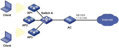
As shown in Figure 4:
· The downlink port of the AC is connected to the hosts, and its uplink port GigabitEthernet 1/0/5 is connected to the Internet.
· The subinterface GigabitEthernet 1/0/5.1 obtains its IP address through DHCP.
Configure local PBR so that the AC forwards SNMP packets and SNMP traps through the subinterface GigabitEthernet 1/0/5.1.
Configuration procedure
# Configure the subinterface GigabitEthernet 1/0/5.1 to obtain its IP address through DHCP.
<AC> system-view
[AC] interface gigabitethernet1/0/5.1
[AC-GigabitEthernet1/0/5.1] ip address dhcp-alloc
[AC-GigabitEthernet1/0/5.1] vlan-type dot1q vid 1
[AC-GigabitEthernet1/0/5.1] quit
# Configure ACL 3000 to match SNMP packets and SNMP traps.
[AC] acl number 3000
[AC-acl-adv-3000] rule 0 permit udp source-port eq snmp
[AC-acl-adv-3000] rule 5 permit udp destination-port eq snmptrap
[AC-acl-adv-3000] quit
# Configure Node 1 for policy management to forward management packets through GigabitEthernet 1/0/5.1. (Because GigabitEthernet 1/0/5.1 obtains its IP address through DHCP and the next hop address is unknown, specify the gateway address learned through DHCP as the next hop address.)
[AC] policy-based-route management permit node 1
[AC-pbr-management-1] if-match acl 3000
[AC-pbr-management-1] apply output-interface gigabitethernet1/0/5.1 ip-address next-hop dhcpc
[AC-pbr-management-1] quit
# Configure local PBR by applying policy management on the AC.
[AC] ip local policy-based-route management
