- Table of Contents
-
- 04-Layer 3 Configuration Guide
- 00-Preface
- 01-ARP Configuration
- 02-IP Addressing Configuration
- 03-DHCP Configuration
- 04-DHCPv6 Configuration
- 05-DNS Configuration
- 06-IPv6 DNS Configuration
- 07-NAT Configuration
- 08-Adjacency Table Configuration
- 09-Flow Classification Configuration
- 10-IPv6 Basics Configuration
- 11-IP Performance Optimization Configuration
- 12-IP Routing Basics
- 13-Static Routing Configuration
- 14-IPv6 Static Routing Configuration
- 15-GRE Configuration
- 16-RIP Configuration
- 17-RIPng Configuration
- 18-Policy-Based Routing Configuration
- Related Documents
-
| Title | Size | Download |
|---|---|---|
| 07-NAT Configuration | 256.54 KB |
Configuring address translation
Configuring an internal server
Configuring aging out NAT entries upon master link failure
Displaying and maintaining NAT
Static NAT configuration example
Dynamic NAT configuration example
Common internal server configuration example
NAT DNS mapping configuration example
Configuring NAT
Support for this feature depends on the device model. For more information, see About the H3C Access Controllers Configuration Guides.
Overview
Network Address Translation (NAT) provides a way to translate an IP address in the IP packet header to another IP address. NAT enables a large number of private users to access the Internet by using a small number of public IP addresses. NAT effectively alleviates the depletion of IP addresses.
A private IP address is used only in an internal network, whereas a public or external IP address is used on the Internet and is globally unique.
According to RFC 1918, three blocks of IP addresses are reserved for private networks:
· In Class A, 10.0.0.0 to 10.255.255.255.
· In Class B, 172.16.0.0 to 172.31.255.255.
· In Class C, 192.168.0.0 to 192.168.255.255.
No host with an IP address in the three ranges exists on the Internet. You can use those IP addresses in an enterprise network freely without requesting them from an ISP or a registration center.
In addition to translating private addresses to public addresses, NAT can also perform address translation between any two networks. In this document, the two networks refer to an internal network and an external network. Generally, a private network is an internal network and a public network is an external network.
Figure 1 shows the NAT operation.
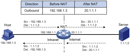
1. The internal host with IP address 192.168.1.3 sends an IP packet to the external server with IP address 1.1.1.2 through the NAT device.
2. Upon receiving the packet, the NAT device checks the IP header and finds that it is destined to the external network. The NAT device then translates the private address 192.168.1.3 to the globally unique public address 20.1.1.1 and forwards the packet to the server on the external network. Meanwhile, the NAT device adds the mapping of the two addresses into its NAT table.
3. The external server responds to the internal host with an IP packet whose destination IP address is 20.1.1.1. Upon receiving the packet, the NAT device checks the IP header, looks into its NAT table for the mapping, replaces the destination address with the private address of 192.168.1.3, and then sends the new packet to the internal host.
The NAT operation is transparent to the terminals involved. The external server believes that the IP address of the internal PC is 20.1.1.1 and is unaware of the private address 192.168.1.3. As such, NAT hides the private network from the external networks.
Despite the advantages of allowing internal hosts to access external resources and providing privacy, NAT also has the following disadvantages:
· Because NAT involves translation of IP addresses, the IP headers cannot be encrypted. This is also true of the application protocol packets when the contained IP address or port number needs to be translated. For example, you cannot encrypt an FTP connection, or its port command cannot work correctly.
· Network debugging becomes more difficult. For example, when a host in a private network tries to attack other networks, it is harder to pinpoint the attacking host because the host IP address has been hidden.
NAT control
Typically, an enterprise allows some hosts in the internal network to access external networks and prohibits others. The enterprise can achieve this through the NAT control mechanism. If a source IP address is among addresses denied, the NAT device does not translate the address. In addition, the NAT device only translates private addresses to specified public addresses.
You can achieve NAT control through an access control list (ACL) and an address pool.
· Only packets matching the ACL rules are served by NAT.
· An address pool is a collection of consecutive public IP addresses for address translation. You can specify an address pool based on the number of available public IP addresses, the number of internal hosts, and network requirements. The NAT device selects an address from the address pool as the public address of an IP packet.
NAT operation
Basic NAT
As shown in Figure 1, when an internal host accesses an external network, the NAT device uses a public IP address to replace the private source IP address. In Figure 1, NAT uses the IP address of the outgoing interface as the public IP address. All internal hosts use the same public IP address to access external networks and only one host can access external networks at a given time.
A NAT device can also hold multiple public IP addresses to support concurrent access requests. Whenever a new external network access request comes from the internal network, the NAT device chooses an available public IP address to replace the source IP address, adds the mapping to its NAT table, and forwards the packet. In this way, multiple internal hosts can access external networks simultaneously.
The number of public IP addresses that a NAT device needs is usually far less than the number of internal hosts because not all internal hosts access external networks at the same time. The number of public IP addresses is related to the number of internal hosts that might access external networks simultaneously during peak hours.
NAPT
Network Address Port Translation (NAPT) is a variation of basic NAT. It allows multiple internal addresses to be mapped to the same public IP address, which is called multiple-to-one NAT.
NAPT mapping is based on both the IP address and the port number. With NAPT, packets from multiple internal hosts are mapped to the same external IP address with different port numbers.
Figure 2 NAPT operation

As shown in Figure 2, three IP packets arrive at the NAT device. Packets 1 and 2 are from the same internal address but have different source port numbers. Packets 1 and 3 are from different internal addresses but have the same source port number. NAPT maps the three IP packets to the same external address but with different source port numbers. Therefore, the packets can still be differentiated. When receiving the response packets, the NAT device forwards them to the corresponding hosts according to the destination addresses and port numbers.
NAPT improves utilization of IP address resources, enabling more internal hosts to access the external network at the same time.
The NAT device uses entries, each of which includes the source IP address, source port number, and protocol type to translate addresses and filter packets. The same NAPT mapping applies to packets sent from the same internal IP address and port to any external IP address and port. The NAT device also allows external hosts to access the internal network by using the translated external addresses and port numbers. This mode facilitates communication among hosts that connect to different NAT devices.
Internal server
NAT hides the internal network structure, including the identities of internal hosts. However, external hosts might need to access some internal hosts such as an internal Web server or FTP server. NAT satisfies this need by supporting internal servers.
You can configure an internal server on the NAT device by mapping a public IP address and port number to the private IP address and port number of the internal server. For instance, you can configure an address like 20.1.1.12:8080 as an internal Web server's external address and port number.
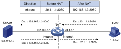
In Figure 3, when the NAT device receives a packet destined for the public IP address of an internal server, it looks in the NAT entries and translates the destination address and port number in the packet to the private IP address and port number of the internal server. When the NAT device receives a response packet from the internal server, it translates the source private IP address and port number of the packet into the public IP address and port number of the internal server.
Figure 3 Internal server operation
DNS mapping
Generally, the DNS server and users that need to access internal servers reside on the public network. You can specify an external IP address and a port number for an internal server on the public network interface of a NAT device, so that external users can access the internal server using its domain name or pubic IP address. In Figure 4, an internal host wants to access an internal Web server by using its domain name, when the DNS server is located on the public network. Typically, the DNS server replies with the public address of the internal server to the host and so the host cannot access the internal server. The DNS mapping feature can solve the problem.
Figure 4 Operation of NAT DNS mapping

A DNS mapping entry records the domain name, public address, public port number, and protocol type of an internal server. Upon receiving a DNS reply, the NAT-enabled interface matches the domain name in the message against the DNS mapping entries. If a match is found, the private address of the internal server is found and the interface replaces the public IP address in the reply with the private IP address. Then, the host can use the private address to access the internal server.
Easy IP
Easy IP uses the public IP address of an interface on the device as the translated source address to save IP address resources, and uses ACLs to permit only certain internal IP addresses to be NATed.
NAT configuration task list
|
Task |
Remarks |
|
|
Either is required. |
||
|
Required. |
||
|
Optional. |
||
|
Optional. |
||
|
Optional. |
||
|
Optional. |
||
|
Optional. |
||
If the NAT configuration (address translation or internal server configuration) on an interface is changed, save the configuration and reboot the device, to avoid the following problems:
· After you delete the NAT-related configuration, address translation can still work for sessions already created.
· If you configure NAT when NAT is running, the same configuration might have different results because of different configuration orders.
Configuring address translation
A NAT device can be configured with or dynamically generate mappings to translate between internal and external network addresses. Address translation can be classified into static and dynamic NAT.
· Static NAT—Mappings between external and internal network addresses are manually configured. Static NAT can meet fixed access requirements of a few users.
· Dynamic NAT—A dynamic NAT entry is generated dynamically. Dynamic NAT is implemented by associating an ACL with an address pool (or the address of an interface in the case of Easy IP). This association defines what packets can use the addresses in the address pool (or the interface's address) to access the external network. An IP address is selected from the associated address pool to translate an outgoing packet. After the session terminates, the selected IP address is released. Dynamic NAT can meet external access requirements of a large number of users.
Configuring static NAT
You must configure static NAT in system view, and make it effective in interface view.
Static NAT translates a private IP address into a public IP address.
To configure static NAT:
|
Step |
Command |
|
1. Enter system view. |
system-view |
|
2. Configure a static NAT mapping. |
nat static [ acl-number ] local-ip global-ip |
|
3. Enter interface view. |
interface interface-type interface-number |
|
4. Enable static NAT on the interface. |
nat outbound static [ track vrrp virtual-router-id ] |
Configuring dynamic NAT
Dynamic NAT is usually implemented by associating an ACL with an address pool (or the address of an interface) on an interface.
· To select the address of an interface to be the translated address, use Easy IP.
· To select an address from an address pool to be the translated address, use No-PAT for dynamic address translation. No-PAT is used in many-to-many address translation but does not translate TCP/UDP port numbers.
Configuration prerequisites
· Configure an ACL to specify IP addresses permitted to be translated. For more information about ACL, see ACL and QoS Configuration Guide.
· Determine whether to use an interface's IP address as the translated source address.
· Determine a public IP address pool for address translation.
· Determine whether to translate port information.
Configuring NAT address pools
The NAT device selects an IP address from a specific NAT address pool to be the source address of a packet.
To configure an address pool:
|
Step |
Command |
Remarks |
|
1. Enter system view. |
system-view |
N/A |
|
2. Configure an address pool. |
nat address-group group-number start-address end-address [ level level ] |
Address pools must not overlap. |
Configuring Easy IP
Easy IP allows the device to use the IP address of one of its interfaces as the source address of NATed packets.
To configure Easy IP:
|
Step |
Command |
|
1. Enter system view. |
system-view |
|
2. Enter interface view. |
interface interface-type interface-number |
|
3. Enable Easy IP by associating an ACL with the IP address of the interface. |
nat outbound [ acl-number ] [ track vrrp virtual-router-id ] |
Configuring No-PAT
With a specific ACL associated with an address pool or interface address, No-PAT translates the source address of a packet permitted by the ACL into an IP address of the address pool or the interface address, without using the port information.
To configure No-PAT:
|
Step |
Command |
|
1. Enter system view. |
system-view |
|
2. Enter interface view. |
interface interface-type interface-number |
|
3. Configure No-PAT by associating an ACL with an IP address pool on the outbound interface for translating only IP addresses. |
nat outbound [ acl-number ] address-group group-number no-pat [ track vrrp virtual-router-id ] |
Configuring NAPT
With a specific ACL associated with an address pool or interface address, NAPT translates the source address of a packet permitted by the ACL into an IP address of the address pool or the interface address, with using the port information.
To configure NAPT:
|
Step |
Command |
|
1. Enter system view. |
system-view |
|
2. Enter interface view. |
interface interface-type interface-number |
|
3. Configure NAPT by associating an ACL with an IP address pool on the outbound interface for translating both IP address and port number. |
nat outbound [ acl-number ] [ address-group group-number ] [ track vrrp virtual-router-id ] |
Configuring an internal server
To configure an internal server, you must map an external IP address and port number to the internal server. This is done by executing the nat server command on an interface.
Internal server configurations include external network information (external IP address global-address and external port number global-port), internal network information (internal IP address local-address and internal port number local-port), and internal server protocol type.
After mapping the internal IP address/port number (local-address and local-port) of a common internal server to an external IP address/port number (global-address and global-port), hosts in external networks can access the server located in the internal network.
The device supports using the interface address as the external address of an internal server, which is the Easy IP feature. If you want to specify an interface, the interface must be a loopback interface and must already exist.
If you configure an internal server using Easy IP but do not configure an IP address for the interface, the internal server configuration does not take effect.
To configure a common internal server:
|
Step |
Command |
Remarks |
|
1. Enter system view. |
system-view |
N/A |
|
2. Enter interface view. |
interface interface-type interface-number |
N/A |
|
3. Configure a common internal server. |
· nat server protocol pro-type global { global-address | current-interface | interface interface-type interface-number } [ global-port ] inside local-address [ local-port ] [ track vrrp virtual-router-id ] · nat server protocol pro-type global { global-address | current-interface | interface interface-type interface-number } global-port1 global-port2 inside local-address1 local-address2 local-port [ track vrrp virtual-router-id ] |
Use either command. |
Configuring DNS mapping
With DNS mapping, an internal host can access an internal server on the same private network by using the domain name of the internal server when the DNS server resides on the public network.
To configure a DNS mapping:
|
Step |
Command |
|
1. Enter system view. |
system-view |
|
2. Configure a DNS mapping. |
nat dns-map domain domain-name protocol pro-type ip global-ip port global-port |
Configuring NAT aging time
NAT aging time configuration supports multiple protocols.
To set the NAT aging time:
|
Step |
Command |
Remarks |
|
1. Enter system view. |
system-view |
N/A |
|
2. Set NAT aging time for a specific protocol. |
nat aging-time { dns | ftp-ctrl | ftp-data | icmp | no-pat | pptp | tcp | tcp-fin | tcp-syn | udp } seconds |
Optional. The default NAT aging time varies by protocol: · 10 seconds for DNS. · 300 seconds for FTP control links. · 300 seconds for FTP data links. · 10 seconds for ICMP. · 240 seconds in NO-PAT mode. · 300 seconds for PPTP. · 300 seconds for TCP. · 10 seconds for TCP FIN and RST connections. · 10 seconds for TCP SYN connections. · 240 seconds for UDP. |
Configuring NAT ALG
NAT ALG configuration supports multiple protocols.
To configure NAT ALG:
|
Step |
Command |
Remarks |
|
|
1. Enter system view. |
system-view |
N/A |
|
|
2. Enable NAT ALG. |
nat alg { all | dns | ftp | ils | nbt | pptp } |
Optional. Enabled by default. |
|
Configuring NAT logging
With NAT logging enabled, a NAT device logs IP address translation information such as the source IP address, source port number, destination IP address, destination port number, translated source IP address, translated source port number and user operations.
As multiple internal users share the same external IP address or the same range of external IP addresses when accessing external networks through a NAT device, it is hard to identify each of the users. The NAT logging function helps in tracking access of internal users to external networks, thus enhancing network security.
NAT logging logs only access of internal network users to external networks. It does not log access of external users to internal servers.
Enabling NAT logging
To enable NAT logging:
|
Step |
Command |
Remarks |
|
|
1. Enter system view. |
system-view |
N/A |
|
|
2. Enable NAT logging. |
nat log enable [ acl acl-number ] |
Disabled by default. |
|
|
3. Enable NAT logging. |
· Enable logging of NAT session
establishment events: · Enable logging for active NAT sessions
and set the logging interval: |
Use either command. By default: · No log is generated when a NAT session is established. · Logging for active NAT sessions is disabled. |
|
Exporting NAT logs
NAT logs can be exported to either the information center or the log server:
· To the information center—NAT logs are converted into system logs and exported to the local device's information center. Depending on the configuration of the information center, NAT logs are then exported to their final destination. Up to 10 NAT logs can be exported to the information center at one time.
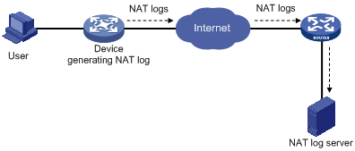
· To the log server—NAT logs are encapsulated into UDP packets and sent to the log server, as shown in Figure 5. The output NAT logs can be in several versions, each with a different UDP packet format. Only version 1 is used. A UDP packet is composed of a header and one or more NAT logs.
If you configure both destinations, the system automatically exports NAT logs to the information center
Figure 5 Exporting NAT logs to the NAT log server
Exporting NAT logs to the information center
Exporting NAT logs to the information center consumes storage space of the device. Use this approach when the volume of NAT logs is relatively small.
NAT logs to the information center are prioritized as informational, meaning that they are ordinary message information. For more information about NAT log priority, see Network Management and Monitoring Configuration Guide.
To configure the device to export NAT logs to the information center:
|
Step |
Command |
Remarks |
|
1. Enter system view. |
system-view |
N/A |
|
2. Export NAT logs to the information center. |
userlog nat syslog |
NAT logs are exported to the NAT log server by default. |
Exporting NAT logs to the log server
For the device to export NAT logs to the log server in UDP packets, you can configure three parameters:
· IP address and UDP port number of the NAT log server. NAT logs cannot be exported successfully if you do not configure the information center export direction and specify the log server address.
· Source IP address of NAT logs. This address allows the log server to identify the log source. Use the loopback interface address as the source IP address of NAT logs.
· Version number of NAT logs. NAT logs may come in several versions, each with a different packet format. The device supports only version 1.
On a distributed device–Centralized IRF device–In standalone mode, you can specify a separate log server for each interface card identified by slot slot-number to implement load sharing on log servers.
On a distributed device–In IRF mode, you can specify a separate log server for each interface card identified by chassis chassis-number to implement load sharing on log servers.
To configure the device to export NAT logs to a NAT log server:
|
Step |
Command |
Remarks |
|
1. Enter system view. |
system-view |
N/A |
|
2. Specify the IP address and UDP port number of the NAT log server. |
userlog nat export host { ipv4-address | ipv6 ipv6-address } udp-port |
Required. |
|
3. Specify the source IP address for the UDP packets that carry NAT logs. |
userlog nat export source-ip ip-address |
Optional. By default, the source IP address is the IP address of the interface through which the UDP packets are sent. |
|
4. Specify the version number of the NAT log packets. |
userlog nat export version version-number |
Optional. Version 1 by default. |
Configuring aging out NAT entries upon master link failure
In a link backup environment where NAT is enabled on the master and backup interfaces of a gateway device, if the master link fails, the backup link switches to the master state. If this feature is enabled on the gateway, all existing NAT entries on the failed link are aged out immediately, so that new NAT entries can be created for subsequent packets on the new master link, and thus existing NAT streams can be directed to the new link immediately.
To enable aging out NAT entries upon master link failure:
|
Step |
Command |
Remarks |
|
1. Enter system view. |
system-view |
N/A |
|
2. Configure aging out NAT entries upon master link failure. |
nat link-down reset-session enable |
Disabled by default. |
Displaying and maintaining NAT
|
Task |
Command |
Remarks |
|
Display information about NAT address pools. |
display nat address-group [ group-number ] [ | { begin | exclude | include } regular-expression ] |
Available in any view. |
|
Display NAT aging time. |
display nat aging-time [ | { begin | exclude | include } regular-expression ] |
Available in any view. |
|
Display all NAT configuration information. |
display nat all [ | { begin | exclude | include } regular-expression ] |
Available in any view. |
|
Display NAT configuration information. |
display nat bound [ | { begin | exclude | include } regular-expression ] |
Available in any view. |
|
Display DNS mapping configuration information. |
display nat dns-map [ | { begin | exclude | include } regular-expression ] |
Available in any view. |
|
Display NAT logging configuration information. |
display nat log [ | { begin | exclude | include } regular-expression ] |
Available in any view. |
|
Display internal server information. |
display nat server [ | { begin | exclude | include } regular-expression ] |
Available in any view. |
|
Display internal server group information, |
display nat server-group [ group-number ] [ | { begin | exclude | include } regular-expression ] |
Available in any view. |
|
Display NAT entry information. |
display nat session [ source { global global-address | inside inside-address } ] [ destination dst-address ] [ | { begin | exclude | include } regular-expression ] |
Available in any view. |
|
Display static NAT information. |
display nat static [ | { begin | exclude | include } regular-expression ] |
Available in any view. |
|
Display NAT statistics. |
display nat statistics [ | { begin | exclude | include } regular-expression ] |
Available in any view. |
|
Display NAT log exports to the log server |
display userlog export [ | { begin | exclude | include } regular-expression ] |
Available in any view. |
|
Clear records in the log buffer. |
reset userlog nat logbuffer |
Available in user view. |
|
Clear NAT log exports. |
reset userlog nat export |
Available in user view. |
|
Clear NAT mappings in the memory. |
reset nat session |
Available in user view. |
NAT configuration examples
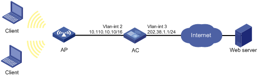
Static NAT configuration example
Network requirements
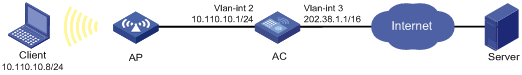
An internal host 10.110.10.8/24 uses public address 202.38.1.100 to access the Internet.
Configuration procedure
# Configure IP addresses for the interfaces. (Details not shown.)
# Configure a one-to-one static NAT mapping.
<AC> system-view
[AC] nat static 10.110.10.8 202.38.1.100
# Enable static NAT on VLAN-interface 3.
[AC] interface Vlan-interface 3
[AC-Vlan-interface3] nat outbound static
[AC-Vlan-interface3] quit
Dynamic NAT configuration example
Network requirements
As shown in Figure 7, a company has three public IP addresses ranging from 202.38.1.1/24 to 202.38.1.3/24, and internal network address 10.110.0.0/16. The company has the requirement that the internal users in subnet 10.110.10.0/24 can access the Internet using public IP addresses 202.38.1.2 and 202.38.1.3, but users in other network segments cannot.
Configuration procedure
# Configure IP addresses for the interfaces. (Details not shown.)
# Configure address pool 1.
<AC> system-view
[AC] nat address-group 1 202.38.1.2 202.38.1.3
# Configure ACL 2001, permitting only users from network segment 10.110.10.0/24 to access the Internet.
[AC] acl number 2001
[AC-acl-basic-2001] rule permit source 10.110.10.0 0.0.0.255
[AC-acl-basic-2001] rule deny
[AC-acl-basic-2001] quit
# Associate address pool 1 and ACL 2001 with the outbound interface VLAN-interface 3 to enable NAPT.
[AC] interface Vlan-interface 3
[AC-Vlan-interface3] nat outbound 2001 address-group 1
[AC-Vlan-interface3] quit
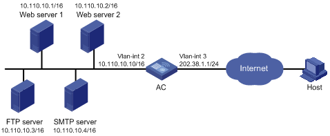
Common internal server configuration example
Network requirements
As shown in Figure 8, a company provides two web servers, one FTP server, and one SMTP server for external users to access. The internal network address is 10.110.0.0/16. The internal address for the FTP server is 10.110.10.3/16, for web server 1 is 10.110.10.1/16, for web server 2 is 10.110.10.2/16, and for the SMTP server 10.110.10.4/16. The company has three public IP addresses ranging from 202.38.1.1/24 to 202.38.1.3/24. Specifically, the company has the following requirements:
· External hosts can access internal servers with public address 202.38.1.1/24.
· Port 8080 is used for web server 2.
Configuration procedure
# Configure IP addresses for the interfaces. (Details not shown.)
# Enter the view of VLAN-interface 3.
<AC> system-view
[AC] interface Vlan-interface 3
# Configure the internal FTP server.
[AC-Vlan-interface3] nat server protocol tcp global 202.38.1.1 21 inside 10.110.10.3 ftp
# Configure the internal web server 1.
[AC-Vlan-interface3] nat server protocol tcp global 202.38.1.1 80 inside 10.110.10.1 www
# Configure the internal web server 2.
[AC-Vlan-interface3] nat server protocol tcp global 202.38.1.1 8080 inside 10.110.10.2 www
# Configure the internal SMTP server.
[AC-Vlan-interface3] nat server protocol tcp global 202.38.1.1 smtp inside 10.110.10.4 smtp
[AC-Vlan-interface3] quit
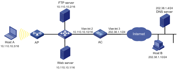
NAT DNS mapping configuration example
Network requirements
As shown in Figure 9, a company provides Web and FTP services to external users, and uses internal IP network segment 10.110.0.0/16. The IP addresses of the Web and FTP servers are 10.110.10.1/16 and 10.110.10.2/16. The company has three public addresses 202.38.1.1/24 through 202.38.1.3/24. The DNS server is at 202.38.1.4/24.
· The public IP address 202.38.1.2 is used to provide services to external users.
· External users can use the public address or domain name of internal servers to access them.
· Internal users can access the internal servers by using their domain names.
Configuration procedure
# Configure IP addresses for the interfaces. (Details not shown.)
# Enter the view of VLAN-interface 3.
<AC> system-view
[AC] interface Vlan-interface 3
# Configure the internal web server.
[AC-Vlan-interface3] nat server protocol tcp global 202.38.1.2 inside 10.110.10.1 www
# Configure the internal FTP server.
[AC-Vlan-interface3] nat server protocol tcp global 202.38.1.2 inside 10.110.10.2 ftp
[AC-Vlan-interface3] quit
# Configure two DNS mapping entries: map the domain name www.server.com of the web server to 202.38.1.2, and ftp.server.com of the FTP server to 202.38.1.2.
[AC] nat dns-map domain www.server.com protocol tcp ip 202.38.1.2 port www
[AC] nat dns-map domain ftp.server.com protocol tcp ip 202.38.1.2 port ftp
[AC] quit
Verifying the configuration
# After completing the configurations, display the DNS mapping configuration information.
<AC> display nat dns-map
NAT DNS mapping information:
There are currently 2 NAT DNS mapping(s)
Domain-name: www.server.com
Global-IP : 202.38.1.2
Global-port: 80(www)
Protocol : 6(TCP)
Domain-name: ftp.server.com
Global-IP : 202.38.1.2
Global-port: 21(ftp)
Protocol : 6(TCP)
Host A and Host B can use the domain name www.server.com to access the web server, and use ftp.server.com to access the FTP server.
Troubleshooting NAT
Symptom 1
IP address translation does not function correctly.
Solution
1. Enable debugging for NAT. Try to locate the problem based on the debugging output information.
2. Use other commands to further identify the problem, if necessary. Pay special attention to the source address after the address translation and make sure this address is the one intended. If not, there might be an address pool bug.
3. Make sure a route is available between the destination network and the address pool segment.
4. Be aware of the possible effects that the firewall or the ACLs have to NAT, and check the route configurations.
Symptom 2
The internal server does not function correctly.
Solution
1. Verify that the internal server host is correctly configured.
2. Verify the router is correctly configured to the internal server parameters, such as the internal server IP address.
3. Use the display acl command to verify that the firewall permits external access to the internal network.
