- Table of Contents
-
- 04-Layer 3 Configuration Guide
- 00-Preface
- 01-ARP Configuration
- 02-IP Addressing Configuration
- 03-DHCP Configuration
- 04-DHCPv6 Configuration
- 05-DNS Configuration
- 06-IPv6 DNS Configuration
- 07-NAT Configuration
- 08-Adjacency Table Configuration
- 09-Flow Classification Configuration
- 10-IPv6 Basics Configuration
- 11-IP Performance Optimization Configuration
- 12-IP Routing Basics
- 13-Static Routing Configuration
- 14-IPv6 Static Routing Configuration
- 15-GRE Configuration
- 16-RIP Configuration
- 17-RIPng Configuration
- 18-Policy-Based Routing Configuration
- Related Documents
-
| Title | Size | Download |
|---|---|---|
| 16-RIP Configuration | 161.76 KB |
Configuring the interface behavior
Configuring an additional routing metric
Configuring RIPv2 route summarization
Disabling host route reception
Configuring inbound/outbound route filtering
Configuring a preference for RIP
Configuring RIP route redistribution
Tuning and optimizing RIP networks
Configuring split horizon and poison reverse
Configuring the maximum number of ECMP routes
Enabling zero field check on incoming RIPv1 messages
Enabling source IP address check on incoming RIP updates
Configuring RIPv2 message authentication
Configuring RIP-to-MIB binding
Configuring the RIP packet sending rate
Displaying and maintaining RIP
Configuring RIP route redistribution
Configuring RIP
Routing Information Protocol (RIP) is a distance-vector simple interior gateway protocol suited to small-sized networks. It employs UDP to exchange route information through port 520.
Overview
RIP uses a hop count to measure the distance to a destination. The hop count from a router to a directly connected network is 0. The hop count from a router to a directly connected router is 1. To limit convergence time, RIP restricts the metric range from 0 to 15. A destination of a metric value of 16 (or greater) is considered unreachable. For this reason, RIP is not suitable for large-sized networks.
RIP route entries
RIP stores routing entries in a database. Each routing entry contains the following elements:
· Destination address—IP address of a destination host or a network.
· Next hop—IP address of the next hop.
· Egress interface—Egress interface of the route.
· Metric—Cost from the local router to the destination.
· Route time—Time elapsed since the last update. The time is reset to 0 every time the routing entry is updated.
· Route tag—Used for route control.
RIP timers
RIP uses the following timers:
· Update timer—Specifies the interval between route updates.
· Timeout timer—Specifies the route aging time. If no update for a route is received within the aging time, the metric of the route is set to 16.
· Suppress timer—Specifies the duration a RIP route stays in suppressed state. When the metric of a route is 16, the route enters the suppressed state. A suppressed route can be replaced by an updated route that is received from the same neighbor before the suppress timer expires and has a metric less than 16.
· Garbage-collect timer—Specifies the interval from when the metric of a route becomes 16 to when it is deleted from the routing table. RIP advertises the route with a metric of 16. If no update is announced for that route before the garbage-collect timer expires, the route is deleted from the routing table.
Routing loop prevention
RIP uses the following mechanisms to prevent routing loops:
· Counting to infinity—A destination with a metric value of 16 is considered unreachable. When a routing loop occurs, the metric value of a route will increment to 16 to avoid endless looping.
· Split horizon—Disables RIP from sending routing information on the interface from which the information was learned to prevent routing loops and save bandwidth.
· Poison reverse—Enables RIP to set the metric of routes received from a neighbor to 16 and sends back these routes to the neighbor so the neighbor can delete such information from its routing table to prevent routing loops.
· Triggered updates—RIP immediately advertises triggered updates for topology changes to reduce the possibility of routing loops and to speed up convergence.
RIP operation
RIP works as follows:
1. RIP sends request messages to neighboring routers. Neighboring routers return response messages containing routing tables.
2. RIP uses the received responses to update the local routing table and sends triggered update messages to its neighbors. All RIP routers on the network do this to learn latest routing information.
3. RIP periodically sends the local routing table to its neighbors. After a RIP neighbor receives the message, it updates its routing table, selects optimal routes, and sends an update to other neighbors. RIP ages routes to keep only valid routes.
RIP versions
There are two RIP versions, RIPv1 and RIPv2.
RIPv1 is a classful routing protocol. It advertises messages through broadcast only. RIPv1 messages do not carry mask information, so RIPv1 can only recognize natural networks such as Class A, B, and C. For this reason, RIPv1 does not support non-contiguous subnets.
RIPv2 is a classless routing protocol. It has the following advantages over RIPv1:
· Supports route tags to implement flexible route control through routing policies.
· Supports masks, route summarization, and CIDR.
· Supports designated next hops to select the best ones on broadcast networks.
· Supports multicasting route updates so only RIPv2 routers can receive these updates to reduce resource consumption.
· Supports simple authentication and MD5 authentication to enhance security.
RIPv2 supports two transmission modes: broadcast and multicast. Multicast is the default mode using 224.0.0.9 as the multicast address. An interface operating in the RIPv2 broadcast mode can also receive RIPv1 messages.
Supported RIP features
The current implementation supports RIPv1 and RIPv2.
Protocols and standards
· RFC 1058, Routing Information Protocol
· RFC 1723, RIP Version 2 - Carrying Additional Information
· RFC 1721, RIP Version 2 Protocol Analysis
· RFC 1722, RIP Version 2 Protocol Applicability Statement
· RFC 1724, RIP Version 2 MIB Extension
· RFC 2082, RIPv2 MD5 Authentication
RIP configuration task list
|
Task |
Remarks |
|
|
Required |
||
|
Optional |
||
|
Optional |
||
|
Optional |
||
|
Optional |
||
|
Optional |
||
|
Optional |
||
|
Optional |
||
|
Optional |
||
|
Optional |
||
|
Optional |
||
|
Optional |
||
|
Optional |
||
|
Optional |
||
|
Optional |
||
|
Optional |
||
|
Optional |
||
Configuring basic RIP
Before you configure basic RIP settings, complete the following tasks:
· Configure the link layer protocol.
· Configure IP addresses for interfaces to ensure IP connectivity between neighboring routers.
Enabling RIP
Perform this task to create a RIP process and enable the RIP process on the interface attached to the specified network. An interface that is not on the specified network does not run RIP.
If you configure RIP settings in interface view before enabling RIP, the settings do not take effect until RIP is enabled. If a physical interface is attached to multiple networks, you cannot advertise these networks in different RIP processes.
To enable RIP:
|
Command |
Remarks |
|
|
1. Enter system view. |
system-view |
N/A |
|
1. Enable a RIP process and enter RIP view. |
rip [ process-id ] |
Disabled by default. |
|
2. Enable RIP on the interface attached to the specified network. |
network network-address |
By default, RIP is disabled on interfaces. |
Configuring the interface behavior
|
Step |
Command |
Remarks |
|
1. Enter system view. |
system-view |
N/A |
|
2. Enter RIP view. |
rip [ process-id ] |
N/A |
|
3. Disable the specified interface from sending routing updates (the interfaces can still receive updates). |
silent-interface { interface-type interface-number | all } |
Optional. All interfaces can send routing updates by default. |
|
4. Return to system view. |
quit |
N/A |
|
5. Enter interface view. |
interface interface-type interface-number |
N/A |
|
6. Enable the interface to receive RIP messages. |
rip input |
Optional. Enabled by default. |
|
7. Enable the interface to send RIP messages. |
rip output |
Optional. Enabled by default. |
Configuring a RIP version
A RIPv1-enabled interface sends RIPv1 broadcasts, and can receive RIPv1 broadcasts and unicasts.
A RIPv2-enabled multicast interface sends RIPv2 multicasts and can receive RIPv2 unicasts, broadcasts, and multicasts.
A RIPv2-enabled broadcast interface sends RIPv2 broadcasts and can receive RIPv1 unicasts and broadcasts, and RIPv2 broadcasts, multicasts, and unicasts.
You can configure a global RIP version in RIP view or an interface-specific RIP version in interface view.
An interface preferentially uses the interface-specific RIP version. If no interface-specific version is specified, the interface uses the global RIP version. If neither global nor interface-specific RIP version is configured, the interface sends RIPv1 broadcasts, and can receives RIPv1 broadcasts and RIPv1 unicasts, and RIPv2 broadcasts, multicasts, and unicasts.
To configure a RIP version:
|
Step |
Command |
Remarks |
|
1. Enter system view. |
system-view |
N/A |
|
2. Enter RIP view. |
rip [ process-id ] |
N/A |
|
3. Specify a global RIP version. |
version { 1 | 2 } |
Optional. By default, if an interface has an interface-specific RIP version, the version takes precedence over the global one. If no interface-specific RIP version is specified, the interface can send RIPv1 broadcasts, and receive RIPv1 broadcasts and unicasts, and RIPv2 broadcasts, multicasts, and unicasts. |
|
4. Return to system view. |
quit |
N/A |
|
5. Enter interface view. |
interface interface-type interface-number |
N/A |
|
6. Specify a RIP version for the interface. |
rip version { 1 | 2 [ broadcast | multicast ] } |
Optional. By default, if an interface has no RIP version specified, the global version takes effect. If no global RIP version is specified, the interface can send RIPv1 broadcasts, and receive RIPv1 broadcasts and unicasts, and RIPv2 broadcasts, multicasts, and unicasts. |
Configuring RIP route control
Before you configure RIP routing feature, complete the following tasks:
· Configure IP addresses for interfaces to ensure IP connectivity between neighboring routers.
· Configure basic RIP.
Configuring an additional routing metric
An additional routing metric (hop count) can be added to the metric of an inbound or outbound RIP route.
An outbound additional metric is added to the metric of a sent route, and it does not change the route's metric in the routing table.
An inbound additional metric is added to the metric of a received route before the route is added into the routing table, and the route's metric is changed. If the sum of the additional metric and the original metric is greater than 16, the metric of the route becomes 16.
To configure additional routing metrics:
|
Step |
Command |
Remarks |
|
1. Enter system view. |
system-view |
N/A |
|
2. Enter interface view. |
interface interface-type interface-number |
N/A |
|
3. Specify an inbound additional routing metric. |
rip metricin value |
Optional. The default setting is 0. |
|
4. Specify an outbound additional routing metric. |
rip metricout value |
Optional. The default setting is 1. |
Configuring RIPv2 route summarization
Perform this task to summarize contiguous subnets into a summary network and sends the network to neighbors. The smallest metric among all summarized routes is used as the metric of the summary route.
Enabling RIPv2 automatic route summarization
Automatic summarization enables RIPv2 to generate a natural network for contiguous subnets. For example, suppose there are three subnet routes 10.1.1.0/24, 10.1.2.0/24, and 10.1.3.0/24. Automatic summarization automatically creates and advertises a summary route 10.0.0.0/8 instead of the more specific routes.
To enable RIPv2 automatic route summarization:
|
Command |
Remarks |
|
|
1. Enter system view. |
system-view |
N/A |
|
2. Enter RIP view. |
rip [ process-id ] |
N/A |
|
3. Enable RIPv2 automatic route summarization. |
summary |
Optional. By default, RIPv2 automatic route summarization is enabled. If the subnets in the routing table are not contiguous, disable automatic route summarization to advertise more specific routes. |
Advertising a summary route
Perform this task to manually configure a summary route.
For example, suppose contiguous subnets routes 10.1.1.0/24, 10.1.2.0/24, and 10.1.3.0/24 exist in the routing table. You can create a summary route 10.1.0.0/16 on GigabitEthernet 1/0/1 to advertise the summary route instead of the more specific routes.
To configure a summary route:
|
Step |
Command |
Remarks |
|
1. Enter system view. |
system-view |
N/A |
|
2. Enter RIP view. |
rip [ process-id ] |
N/A |
|
3. Disable RIPv2 automatic route summarization. |
undo summary |
By default, RIPv2 automatic route summarization is enabled. |
|
4. Return to system view. |
quit |
N/A |
|
5. Enter interface view. |
interface interface-type interface-number |
N/A |
|
6. Configure a summary route. |
rip summary-address ip-address { mask | mask-length } |
N/A |
Disabling host route reception
Perform this task to disable RIPv2 from receiving host routes from the same network and save network resources. This feature does not apply to RIPv1.
To disable RIP from receiving host routes:
|
Step |
Command |
Remarks |
|
1. Enter system view. |
system-view |
N/A |
|
2. Enter RIP view. |
rip [ process-id ] |
N/A |
|
3. Disable RIP from receiving host routes. |
undo host-route |
By default, RIP receives host routes. |
Advertising a default route
You can advertise a default route on all RIP interfaces in RIP view or a specific RIP interface in interface view. The interface view setting takes precedence over the RIP view settings.
To disable an interface from advertising a default route, use the rip default-route no-originate command on the interface.
To configure RIP to advertise a default route:
|
Step |
Command |
Remarks |
|
1. Enter system view. |
system-view |
N/A |
|
2. Enter RIP view. |
rip [ process-id ] |
N/A |
|
3. Enable RIP to advertise a default route. |
default-route { only | originate } [ cost cost ] |
Optional. Not enabled by default. |
|
4. Return to system view. |
quit |
N/A |
|
5. Enter interface view. |
interface interface-type interface-number |
N/A |
|
6. Configure the RIP interface to advertise a default route. |
rip default-route { { only | originate } [ cost cost ] | no-originate } |
Optional. By default, a RIP interface can advertise a default route if the RIP process is configured with default route advertisement. |
|
|
NOTE: The router enabled to advertise a default route does not receive default routes from RIP neighbors. |
Configuring inbound/outbound route filtering
Perform this task to filter inbound and outbound routes by using an ACL or IP prefix list. You can also configure RIP to receive routes only from a specified neighbor.
To configure route filtering:
|
Step |
Command |
Remarks |
|
1. Enter system view. |
system-view |
N/A |
|
2. Enter RIP view. |
rip [ process-id ] |
N/A |
|
3. Configure the filtering of inbound routes. |
filter-policy { acl-number | gateway ip-prefix-name | ip-prefix ip-prefix-name [ gateway ip-prefix-name ] } import [ interface-type interface-number ] |
By default, the filtering of inbound routes is not configured. The filter-policy import command filters inbound routes. Filtered routes are not installed into the routing table or advertised to neighbors. |
|
4. Configure the filtering of outbound routes. |
filter-policy { acl-number | ip-prefix ip-prefix-name } export [ protocol [ process-id ] | interface-type interface-number ] |
By default, the filtering of outbound routes is not configured. The filter-policy export command filters outbound routes, including routes redistributed with the import-route command. |
Configuring a preference for RIP
If multiple IGPs find routes to the same destination, the route found by the IGP that has the highest priority is selected as the optimal route. Perform this task to configure a preference for RIP. The smaller the preference value, the higher the priority.
To configure a preference for RIP:
|
Step |
Command |
Remarks |
|
1. Enter system view. |
system-view |
N/A |
|
2. Enter RIP view. |
rip [ process-id ] |
N/A |
|
3. Configure a preference for RIP. |
preference value |
Optional. The default setting is 100. |
Configuring RIP route redistribution
Perform this task to configure RIP to redistribute routes from other routing protocols, including static and direct routes. Only active routes can be redistributed. To display active routes, use the display ip routing-table protocol command.
To configure RIP route redistribution:
|
Step |
Command |
Remarks |
|
1. Enter system view. |
system-view |
N/A |
|
2. Enter RIP view. |
rip [ process-id ] |
N/A |
|
3. Configure a default metric for redistributed routes. |
default cost value |
Optional. The default setting is 0. |
|
4. Redistribute routes from other routing protocols. |
import-route protocol [ process-id | all-processes ] [ cost cost | tag tag ] * |
By default, route redistribution is disabled. |
Tuning and optimizing RIP networks
Configuration prerequisites
Before you tune and optimize RIP networks, complete the following tasks:
· Configure IP addresses for interfaces to ensure IP connectivity between neighboring nodes.
· Configure basic RIP.
Configuring RIP timers
You can change the RIP network convergence speed by adjusting RIP timers. Based on network performance, configure identical RIP timer settings to avoid unnecessary traffic or route flapping.
To configure RIP timers:
|
Step |
Command |
Remarks |
|
1. Enter system view. |
system-view |
N/A |
|
2. Enter RIP view. |
rip [ process-id ] |
N/A |
|
3. Configure RIP timers. |
timers { garbage-collect garbage-collect-value | suppress suppress-value | timeout timeout-value | update update-value } * |
Optional. By default: · The update timer is 30s. · The timeout timer is 180s. · The suppress timer is 120s. · The garbage-collect timer is 120s. |
Configuring split horizon and poison reverse
The split horizon and poison reverse functions can prevent routing loops. If both split horizon and poison reverse are configured, only the poison reverse function takes effect.
Enabling split horizon
Split horizon disables RIP from sending routes through the interface where the routes were learned to prevent routing loops between adjacent routers.
On NBMA networks such as FR and X.25 where multiple VCs are configured on the primary and secondary interfaces, disable split horizon to ensure correct route advertisement.
Disabling split horizon on point-to-point links does not take effect.
To enable split horizon:
|
Step |
Command |
Remarks |
|
1. Enter system view. |
system-view |
N/A |
|
2. Enter interface view. |
interface interface-type interface-number |
N/A |
|
3. Enable split horizon. |
rip split-horizon |
Optional. By default, split horizon is enabled. |
Enabling poison reverse
Poison reverse allows RIP to send routes through the interface where the routes were learned, but the metric of these routes is always set to 16 (unreachable) to avoid routing loops between neighbors.
To enable poison reverse:
|
Step |
Command |
Remarks |
|
1. Enter system view. |
system-view |
N/A |
|
2. Enter interface view. |
interface interface-type interface-number |
N/A |
|
3. Enable poison reverse. |
rip poison-reverse |
By default, poison reverse is disabled. |
Configuring the maximum number of ECMP routes
Perform this task to implement load sharing over ECMP routes.
To configure the maximum number of ECMP routes:
|
Step |
Command |
Remarks |
|
1. Enter system view. |
system-view |
N/A |
|
2. Enter RIP view. |
rip [ process-id ] |
N/A |
|
3. Configure the maximum number of ECMP routes. |
maximum load-balancing number |
Optional. By default, the maximum number of ECMP routes is 4. |
Enabling zero field check on incoming RIPv1 messages
Some fields in the RIPv1 message must be set to zero. These fields are called "zero fields." You can enable zero field check on incoming RIPv1 messages. If a zero field of a message contains a non-zero value, RIPv1 does not process the message. If you are certain that all messages are trustworthy, disable zero field check to save CPU resources.
This feature does not apply to RIPv2 packets, because they have no zero fields.
To enable zero field check on incoming RIPv1 messages:
|
Step |
Command |
Remarks |
|
1. Enter system view. |
system-view |
N/A |
|
2. Enter RIP view. |
rip [ process-id ] |
N/A |
|
3. Enable zero field check on incoming RIPv1 messages. |
checkzero |
Optional. By default, this function is enabled. |
Enabling source IP address check on incoming RIP updates
Perform this task to enable source IP address check on incoming RIP updates.
Upon receiving a message on an Ethernet interface, RIP compares the source IP address of the message with the IP address of the interface. If they are not in the same network segment, RIP discards the message.
Upon receiving a message on a serial interface, RIP checks whether the source address of the message is the IP address of the peer interface. If not, RIP discards the message.
|
|
IMPORTANT: Disable the source IP address check feature if the RIP neighbor is not directly connected. |
To enable source IP address check on incoming RIP updates:
|
Step |
Command |
Remarks |
|
1. Enter system view. |
system-view |
N/A |
|
2. Enter RIP view. |
rip [ process-id ] |
N/A |
|
3. Enable source IP address check on incoming RIP messages. |
validate-source-address |
Optional. By default, this function is enabled. |
Configuring RIPv2 message authentication
Perform this task to enable authentication on RIPv2 messages. This feature does not apply to RIPv1 because RIPv1 does not support authentication. Although you can specify an authentication mode for RIPv1 in interface view, the configuration does not take effect.
RIPv2 supports two authentication modes: simple authentication and MD5 authentication.
To configure RIPv2 message authentication:
|
Step |
Command |
|
1. Enter system view. |
system-view |
|
2. Enter interface view. |
interface interface-type interface-number |
|
3. Configure RIPv2 authentication. |
rip authentication-mode { md5 { rfc2082 [ cipher ] key-string key-id | rfc2453 [ cipher ] key-string } | simple [ cipher ] password } |
Specifying a RIP neighbor
Usually, RIP sends messages to broadcast or multicast addresses. On non-broadcast or multicast links, you must manually specify RIP neighbors.
Follow these guidelines when you specify a RIP neighbor:
· Do not use the peer ip-address command when the neighbor is directly connected. Otherwise, the neighbor may receive both the unicast and multicast (or broadcast) of the same routing information.
· If a specified neighbor is not directly connected, disable source address check on incoming updates.
To specify a RIP neighbor:
|
Step |
Command |
Remarks |
|
1. Enter system view. |
system-view |
N/A |
|
2. Enter RIP view. |
rip [ process-id ] |
N/A |
|
3. Specify a RIP neighbor. |
peer ip-address |
N/A |
|
4. Disable source address check on incoming RIP updates. |
undo validate-source-address |
By default, this function is not disabled. |
Configuring RIP-to-MIB binding
This task allows you to enable a specific RIP process to receive SNMP requests.
To bind RIP to MIB:
|
Step |
Command |
Remarks |
|
1. Enter system view. |
system-view |
N/A |
|
2. Bind RIP to MIB. |
rip mib-binding process-id |
Optional. By default, MIB is bound to RIP process 1. |
Configuring the RIP packet sending rate
Perform this task to specify the interval for sending RIP packets and the maximum number of RIP packets that can be sent at each interval. This feature can avoid excessive RIP packets from affecting system performance and consuming too much bandwidth.
To configure the RIP packet sending rate:
|
Step |
Command |
Remarks |
|
1. Enter system view. |
system-view |
N/A |
|
2. Enter RIP view. |
rip [ process-id ] |
N/A |
|
3. Specify the interval for sending RIP packets and the maximum number of RIP packets that can be sent at each interval. |
output-delay time count count |
Optional. By default, an interface sends up to three RIP packets every 20 milliseconds. |
Displaying and maintaining RIP
|
Command |
Remarks |
|
|
Display RIP current status and configuration information. |
display rip [ process-id ] [ | { begin | exclude | include } regular-expression ] |
Available in any view. |
|
Display all active routes in RIP database. |
display rip process-id database [ | { begin | exclude | include } regular-expression ] |
Available in any view. |
|
Display RIP interface information. |
display rip process-id interface [ interface-type interface-number ] [ | { begin | exclude | include } regular-expression ] |
Available in any view. |
|
Display routing information about a specified RIP process. |
display rip process-id route [ ip-address { mask | mask-length } | peer ip-address | statistics ] [ | { begin | exclude | include } regular-expression ] |
Available in any view. |
|
Reset a RIP process. |
reset rip process-id process |
Available in user view. |
|
Clear the statistics of a RIP process. |
reset rip process-id statistics |
Available in user view. |
RIP configuration examples
Configuring RIP version
Network requirements
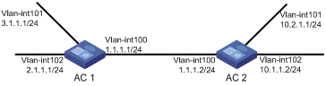
As shown in Figure 1, enable RIPv2 on all interfaces on AC 1 and AC 2.
Configuration procedure
1. Configure IP addresses for interfaces. (Details not shown.)
2. Configure basic RIP:
# Configure AC 1.
<AC1> system-view
[AC1] rip
[AC1-rip-1] network 1.0.0.0
[AC1-rip-1] network 2.0.0.0
[AC1-rip-1] network 3.0.0.0
[AC1-rip-1] quit
# Configure AC 2.
<AC2> system-view
[AC2] rip
[AC2-rip-1] network 1.0.0.0
[AC2-rip-1] network 10.0.0.0
[AC2-rip-1] quit
# Display the RIP routing table on AC 1.
[AC1] display rip 1 route
Route Flags: R - RIP, T - TRIP
P - Permanent, A - Aging, S - Suppressed, G - Garbage-collect
----------------------------------------------------------------------------
Peer 1.1.1.2 on Vlan-interface100
Destination/Mask Nexthop Cost Tag Flags Sec
10.0.0.0/8 1.1.1.2 1 0 RA 9
The output shows that RIPv1 uses natural masks to advertise routing information.
3. Configure a RIP version:
# Configure RIPv2 on AC 1.
[AC1] rip
[AC1-rip-1] version 2
[AC1-rip-1] undo summary
[AC1-rip-1] quit
# Configure RIPv2 on AC 2.
[AC2] rip
[AC2-rip-1] version 2
[AC2-rip-1] undo summary
# Display the RIP routing table on AC 1.
[AC1] display rip 1 route
Route Flags: R - RIP, T - TRIP
P - Permanent, A - Aging, S - Suppressed, G - Garbage-collect
----------------------------------------------------------------------------
Peer 1.1.1.2 on Vlan-interface100
Destination/Mask Nexthop Cost Tag Flags Sec
10.0.0.0/8 1.1.1.2 1 0 RA 87
10.1.1.0/24 1.1.1.2 1 0 RA 19
10.2.1.0/24 1.1.1.2 1 0 RA 19
The output shows that RIPv2 uses classless subnet mask.
|
|
NOTE: After RIPv2 is configured, RIPv1 routes might still exist in the routing table until they are aged out. |
Configuring RIP route redistribution
Network requirements
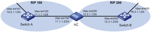
As shown in Figure 2, the AC communicates with Switch A through RIP 100 and with Switch B through RIP 200.
Configure RIP 200 to redistribute direct routes and routes from RIP 100 on the AC so Switch B can learn routes destined for 10.2.1.0/24 and 11.1.1.0/24. Switch A cannot learn routes destined for 12.3.1.0/24 and 16.4.1.0/24.
Configure the AC to not advertise route 10.2.1.1/24 to Switch B.
Configuration procedure
1. Configure IP addresses for interfaces. (Details not shown.)
2. Configure basic RIP:
# Enable RIP 100, and configure RIPv2 on Switch A.
<SwitchA> system-view
[SwitchA] rip 100
[SwitchA-rip-100] network 10.0.0.0
[SwitchA-rip-100] network 11.0.0.0
[SwitchA-rip-100] version 2
[SwitchA-rip-100] undo summary
[SwitchA-rip-100] quit
# Enable RIP 100 and RIP 200, and configure RIPv2 on the AC.
<AC> system-view
[AC] rip 100
[AC-rip-100] network 11.0.0.0
[AC-rip-100] version 2
[AC-rip-100] undo summary
[AC-rip-100] quit
[AC] rip 200
[AC-rip-200] network 12.0.0.0
[AC-rip-200] version 2
[AC-rip-200] undo summary
[AC-rip-200] quit
# Enable RIP 200 and configure RIPv2 on Switch B.
<SwitchB> system-view
[SwitchB] rip 200
[SwitchB-rip-200] network 12.0.0.0
[SwitchB-rip-200] network 16.0.0.0
[SwitchB-rip-200] version 2
[SwitchB-rip-200] undo summary
[SwitchB-rip-200] quit
# Display the IP routing table on Switch B.
[SwitchB] display ip routing-table
Routing Tables: Public
Destinations : 6 Routes : 6
Destination/Mask Proto Pre Cost NextHop Interface
12.3.1.0/24 Direct 0 0 12.3.1.2 Vlan200
12.3.1.2/32 Direct 0 0 127.0.0.1 InLoop0
16.4.1.0/24 Direct 0 0 16.4.1.1 Vlan400
16.4.1.1/32 Direct 0 0 127.0.0.1 InLoop0
127.0.0.0/8 Direct 0 0 127.0.0.1 InLoop0
127.0.0.1/32 Direct 0 0 127.0.0.1 InLoop0
3. Configure RIP route redistribution:
# Configure RIP 200 to redistribute direct routes and routes from RIP 100 on the AC.
[AC] rip 200
[AC-rip-200] import-route rip 100
[AC-rip-200] import-route direct
[AC-rip-200] quit
# Display the IP routing table on Switch B.
[SwitchB] display ip routing-table
Routing Tables: Public
Destinations : 8 Routes : 8
Destination/Mask Proto Pre Cost NextHop Interface
10.2.1.0/24 RIP 100 1 12.3.1.1 Vlan200
11.1.1.0/24 RIP 100 1 12.3.1.1 Vlan200
12.3.1.0/24 Direct 0 0 12.3.1.2 Vlan200
12.3.1.2/32 Direct 0 0 127.0.0.1 InLoop0
16.4.1.0/24 Direct 0 0 16.4.1.1 Vlan400
16.4.1.1/32 Direct 0 0 127.0.0.1 InLoop0
127.0.0.0/8 Direct 0 0 127.0.0.1 InLoop0
127.0.0.1/32 Direct 0 0 127.0.0.1 InLoop0
4. Configure RIP to filter redistributed routes:
# Configure ACL 2000 on the AC to not advertise routes redistributed from RIP 100 to Switch B.
[AC] acl number 2000
[AC-acl-basic-2000] rule deny source 10.2.1.1 0.0.0.255
[AC-acl-basic-2000] rule permit
[AC-acl-basic-2000] quit
[AC] rip 200
[AC-rip-200] filter-policy 2000 export rip 100
# Display the IP routing table on Switch B.
[SwitchB] display ip routing-table
Routing Tables: Public
Destinations : 7 Routes : 7
Destination/Mask Proto Pre Cost NextHop Interface
11.1.1.0/24 RIP 100 1 12.3.1.1 Vlan200
12.3.1.0/24 Direct 0 0 12.3.1.2 Vlan200
12.3.1.2/32 Direct 0 0 127.0.0.1 InLoop0
16.4.1.0/24 Direct 0 0 16.4.1.1 Vlan400
16.4.1.1/32 Direct 0 0 127.0.0.1 InLoop0
127.0.0.0/8 Direct 0 0 127.0.0.1 InLoop0
127.0.0.1/32 Direct 0 0 127.0.0.1 InLoop0
Troubleshooting RIP
No RIP updates received
Symptom
No RIP updates are received when the links work properly.
Analysis
After enabling RIP, use the network command to enable corresponding interfaces. Make sure no interfaces are disabled from handling RIP messages.
If the peer is configured to send multicast messages, the same should be configured on the local end.
Solution
· Use the display current-configuration command to verify RIP configuration.
· Use the display rip command to verify whether an interface is disabled.
Route oscillation occurred
Symptom
When all links work properly, route oscillation occurs on the RIP network. After displaying the routing table, you might find some routes intermittently appear and disappear in the routing table.
Analysis
In the RIP network, make sure that all the same timers within the entire network are identical and have logical relationships between them. For example, the timeout timer value should be greater than the update timer value.
Solution
· Use the display rip command to verify the configuration of RIP timers.
· Use the timers command to adjust timers properly.
