- Table of Contents
-
- H3C S9500 Series Routing Switches Operation Manual-(V1.01)
- 00-1Cover
- 01-Getting Started Operation
- 02-Port Operation
- 03-VLAN-QinQ Operation
- 04-Network Protocol Operation
- 05-Routing Protocol Operation
- 06-Multicast Protocol Operation
- 07-QACL Operation
- 08-MPLS Operation
- 09-STP Operation
- 10-Security Operation
- 11-Reliability Operation
- 12-System Management Operation
- 13-PoE Operation
- 14-NAT-URPF-VPLS Operation
- 15-Integrated Management Operation
- 16-Appendix
- Related Documents
-
| Title | Size | Download |
|---|---|---|
| 14-NAT-URPF-VPLS Operation | 491 KB |
Table of Contents
1.2.5 Configuring Nonstandard FTP Internal Server
1.2.6 Special Protocols Supported by NAT
1.3.1 Configuring an Address Pool
1.3.3 Configuring Internal Servers
1.3.4 Configuring Nonstandard FTP Server
1.3.5 Configuring NAT Blacklist Attributes.
1.3.6 Configuring the Aging Time of NAT Connections
1.3.7 Configuring NAT Security Logging
1.4 Displaying NAT Configuration
2.3 URPF Configuration Example I
2.4 URPF Configuration Example II
3.2 Basic VPLS Network Architectures
3.3 VPLS Operational Principle
3.3.1 VPLS Basic Transmission Components
3.5.1 Configuring Routing Protocols
3.5.2 Configuring Basic MPLS Functions
3.5.3 Configuring LDP Expansion Session Peer
3.5.5 Creating a VPLS Instance
3.5.6 Configuring VLAN for User Access and Binding a VLPS Instance
3.5.7 Configuring Static MAC Address
3.5.8 Enabling VLAN VPN on a Port
3.5.9 Configuring user-defined flow template
3.5.11 Configuring MPLS redirection
3.5.12 Configuring VPLS Characteristics
3.6 Displaying and Debugging VPLS
3.7 VPLS Basic Configuration Example
Chapter 1 NAT Configuration
& Note:
The service processor cards mentioned in this chapter refer to LSBM1NATB boards.
1.1 NAT Overview
1.1.1 Introduction to NAT
As described in RFC3022, network address translation (NAT) is the procedure translating the IP address in the header of an IP data packet into another IP address. By using abundant private IP addresses, NAT supports private networks with limited public IP addresses to access the Internet, and therefore saves the IP address resources
& Note:
Private IP addresses refer to the addresses of hosts on an intranet. Public IP addresses refer to IP addresses globally unique on the Internet.
RFC1918 reserves the following three blocks of IP addresses for private networks:
l Class A: from 10.0.0.0 to 10.255.255.255
l Class B: from 172.16.0.0 to 172.31.255.255
l Class C: from 192.168.0.0 to 192.168.255.255
IP addresses in the above three blocks are not for use on the Internet, and users can use them within their enterprises freely without applying to the ISP or NIC.
Figure 1-1 depicts a basic NAT application.
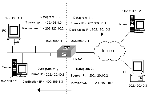
Figure 1-1 Basic NAT procedure
As shown in Figure 1-1, the switch used as a NAT device is located at the joint of the enterprise intranet and the external networks, and packets are exchanged between an internal PC and an external server as follows:
l When packet 1 sent from the internal PC with IP address 192.168.1.3 to the external server with IP address 202.120.10.2 arrives at the NAT device, the NAT process checks the packet header and finds that the packet is destined for an external site and be consistent with NAT rules. Then, the process translates the private IP address of 192.168.1.3 in the source address field of the packet header into public IP address 202.169.10.1, which can be identified on the Internet, and sends the packet out on demand while recording the address mapping in the NAT table.
l When response packet 2 sent from the external server to the internal PC with destination address 202.169.10.1 arrives at the NAT device, the NAT process checks the contents of the packet header, looks up the corresponding mapping in the NAT table, and replaces the destination address in the packet header with the private IP address of the internal PC.
The previously described NAT procedure is transparent to the communicating ends such as the internal PC and external server in Figure 1-1. The external server assumes that the IP address of the internal PC is 202.169.10.1 and does not know the address 192.168.1.3 at all. In this way, NAT ‘hides’ the enterprise intranet.
The advantage of NAT is that it enables internal hosts to access the external network resources with privacy protected. However, it has also a disadvantage: if a packet has an IP address or a port requiring NAT embedded in its header, the packet cannot be encrypted. For example, the encrypted FTP connection cannot be used; otherwise, the FTP port cannot be translated correctly.
1.2 NAT Features
1.2.1 NAT and NAT Control
According to the NAT procedure illustrated in Figure 1-1, when an internal host tries to access the external networks, NAT selects a proper public address and substitutes it for the source address in the packets. In Figure 1-1, the IP address defined on the outbound interface of the NAT server is selected. In this case, only one internal host can access external networks at a time. This mode is called one-to-one NAT. When multiple internal hosts request to access external networks simultaneously, this type of NAT can only satisfy one of them.
A variation of NAT responds to concurrent requests. It allows a NAT device to be equipped with multiple public IP addresses. When the first internal host tries to access external networks, the NAT process selects a public address for it and adds a mapping record in the NAT table; when the second internal host tries to access external networks, the NAT process selects another public address, and so on. In this way, concurrent requests from multiple internal hosts are satisfied. This mode is called many-to-many NAT.
The features of the two NAT modes are described in the following table:
|
Mode |
Feature |
|
One-to-one NAT |
The NAT server has only one public IP address. Only one internal host can access external networks at a time. |
|
Many-to-many NAT |
The NAT server has multiple public IP addresses. Concurrent requests from multiple internal hosts can be satisfied. |
& Note:
l Since the probability for all internal hosts to request to access external networks is very low, the number of internal hosts can be much larger than that of public addresses for the NAT server.
The number of public IP addresses needed depends on the statistical number of internal hosts that may request to access external networks at traffic peak.
In practice, it is possible that only some specific internal hosts are expected to have access to the Internet. That is, when the NAT process checks the header of a packet, it determines whether the included source IP address is in the address range with Internet access authority, and refuses to perform address translation for those ineligible. In a word, this involves NAT control.
Many-to-many NAT can be implemented by defining an address pool, and the control of NAT can be achieved by employing access control lists (ACLs).
An address pool is a collection of public IP addresses for NAT. Its configuration depends on the number of available public IP addresses, the number of internal hosts, and the practical application. During address translation, the NAT process selects an address from the address pool to use as the translated source address.
The control of NAT is implemented by using ACLs. Only packets matching the ACL criteria can obtain NAT service. In this way, the application of NAT is effectively controlled, making only some specific hosts have the authority to access the Internet.
1.2.2 NAPT
NAT maps an Internal IP address to an external IP address and creates a corresponding entry in the address mapping table, and the external IP address is then unavailable to any hosts other than the one currently using it if the address mapping entry does not get purged. Different from NAT, NAPT (network address port translation) is capable of mapping an IP address to multiple IP addresses or mapping a group of IP addresses to another group of IP addresses. That is, NAPT saves external address resource more efficiently. NAPT is also known as PAT (Port Address Translation) or Address Overloading.
NAPT involves the mapping of IP addresses and transport layer protocol port numbers. NAPT maps multiple sessions, each of which has its own source address, to different ports of the same external address, through which multiple internal addresses can multiplex one or more external addresses.
The following figure illustrates the fundamentals of NAPT.
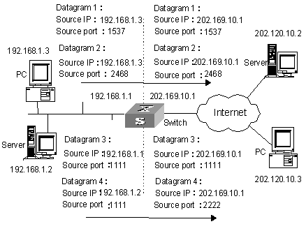
Figure 1-2 NAPT address multiplexing
As shown in the above figure, four packets containing internal addresses arrive at the switch acting as the NAT equipment:
l Packets 1 and 2 are from the same internal address but have different source port numbers.
l Packets 3 and 4 are from different internal addresses but have the same source port number.
By using NAPT mapping, the four packets are translated into the same public address, but are given different source port numbers. In this way, the differences between the four packets are kept, and the NAT process can distinguish the response packets for each of them by destination address and port number.
1.2.3 Easy IP
NAT with the Easy IP feature uses the public address of the VLAN interface on the NAT equipment as the translated source addresses. If you have only one public network IP address available or you have a limited number of internal IP addresses to be translated, you can use Easy IP to implement NAT.
1.2.4 Internal Servers
NAT conceals the internal network topology and acts as a shield for internal hosts. But in practical applications, it might be required to provide some chances for external hosts to access certain internal devices such as internal WWW servers or FTP servers. By using NAT, you can flexibly add internal servers. For instance, you can use 202.169.10.10 as the public address for an internal WWW server, and 202.110.10.11 as that for an FTP server. You can even use 202.110.10.12:8080 as the public address for an internal WWW server.
1.2.5 Configuring Nonstandard FTP Internal Server
A nonstandard FTP internal server is different from a common FTP internal server in that its private network port can use other ports in addition to the default port of FTP, namely port 21. In the configuration of a standard FTP internal server, the public network can use ports ranging from port 0 to port 12287, but its private network must use port 21 in order to be identified as an FTP internal server; In a nonstandard FTP internal server, the public network port is still from port 0 to port 12287 and the private network port is from port 0 to port 65535. Note that other identified ports except the default port 21 cannot be used.
1.2.6 Special Protocols Supported by NAT
The special protocols supported by NAT include ICMP (Internal Control Message Protocol), DNS (Domain Name System), ILS (Internet Locator Service), H.323, and FTP (File Transfer Protocol).
1.3 NAT Configuration
The following table describes the NAT configuration tasks.
|
Configuration Item |
Command |
Description |
|
Enter the system view |
system-view |
- |
|
Configure an address pool |
nat address-group group-number start-addr end-addr |
Required |
|
Enter the VLAN interface view |
interfacevlan-interface vlan-id |
- |
|
Configure NAT |
nat outbound acl-number [ address-group group-number [ no-pat ] ] slot slotno |
Required, implement different NAT modes by configuring different parameters |
|
Configure internal server |
nat server protocol pro-type global global-addr global-port1 [ global-port2 ] inside host-addr1 [ host-addr2 ] host-port slot slotno or nat server protocol pro-type global global-addr [ global-port ] inside host-addr [ host-port ] slot slotno |
Optional |
|
Configure nonstandard FTP internal server |
nat ftp server global global-addr global-port inside host-addr host-port slot slotno |
Optional |
|
Configure NAT blacklist attributes |
nat blacklist start |
Optional |
|
Configure the aging time of NAT connections |
nat aging-time { alg time-value | np slow } |
Optional |
|
Clear NAT mapping tables from a memory and a network processor (NP) |
reset nat session slot slotno |
Optional |
After you configure the internal FTP server, the FTP clients of the public network can access the internal FTP server of the private network in the Passive manner. If the FTP client of the public network wants to access the internal FTP server of the private network in the Port manner, only FTP servers using port 20 as the data port are supported. If the internal FTP server does not use port 20 as the data port, you must configure the NAT rules corresponding to the internal FTP server to enable the services being provided smoothly and data connection and controlling connection using the same public address for NAT. That is, one address pool is bound to the NAT rule, and the address of the address pool and the public address of the internal FTP server are overlapped.
1.3.1 Configuring an Address Pool
An address pool is a collection of consecutive public IP addresses. If its starting IP address and ending IP address are the same, there is only one address in the address pool.
During address translation, the NAT server selects an IP address from the address pool to be the translated source address. Use the nat address-group command to configure an address pool.
Perform the following configuration in system view.
Table 1-3 Configure an address pool
|
Operation |
Command |
|
Configure an address pool |
nat address-group group-number start-addr end-addr |
|
Delete an address pool |
undo nat address-group group-number |
![]() Caution:
Caution:
l The number of addresses included in this address pool (all the public addresses in the address pool) cannot exceed 256.
l Network segment addresses and broadcast addresses cannot be configured as the addresses of an address pool.
l Any IP address in a NAT address pool cannot be used in the internal network.
l You cannot delete an address pool associated to an ACL.
l There need to be less than three addresses in a NAT address pool when NAPT is enabled.
1.3.2 Configuring NAT
By configuring the association between ACLs and the NAT address pool (or the interface addresses), you can make the NAT server perform address translation for packets matching the ACL criteria only. Before a packet from the intranet is forwarded to external networks, it is first checked against the ACLs to see if it matches the translation criteria. If it does, the NAT process will find the corresponding address pool or the interface address by referring to the association, and then translate it.
Use the nat outbound command to associate an ACL with an address pool or interface address. Different NAT modes need different configurations.
![]() Caution:
Caution:
If you disable NAT or NAPT and then want to enable them again, it is recommended that you execute the reset nat session slot command.
I. Configuring NAT
Use the following command to associate an ACL with an address pool and specify an LSBM1NATB board to process NAT services.
Perform the following configuration in VLAN interface view.
Table 1-4 Configure one-to-one NAT
|
Operation |
Command |
|
Configure one-to-one NAT |
nat outbound acl-number address-group group-number no-pat slot slotno |
|
Cancel one-to-one NAT |
undo nat outbound acl-number address-group group-number no-pat slot slotno |
& Note:
As for the ACL associated with an address pool, only the source IP address and the destination IP address in it are used. They are also used to tell whether or not two rules conflict.
The no-pat keyword indicates that only IP addresses included in data packets are translated while the port number information in the TCP/UDP protocol is left unchanged. That is, NAT is based on the mapping between the internal IP address and the external IP address only.
II. Configuring NAPT
Use the following command to associate an ACL with an address pool to implement NAPT.
Perform the following configuration in VLAN interface view.
|
Operation |
Command |
|
Configure NAPT |
nat outbound acl-number address-group group-number slot slotno |
|
Cancel NAPT |
undo nat outbound acl-number address-group group-number slot slotno |
By comparing Table 1-4 and Table 1-5, we can draw the following conclusions:
l With the no-pat keyword, only the IP addresses of data packets are translated while the port number information remains unchanged, that is, one-to-one NAT.
l Without the no-pat keyword, NAPT is enabled, and you can implement many-to-many NAT.
![]() Caution:
Caution:
In the NAPT mode, the address pool can have up to three addresses.
III. Configuring the Easy IP feature
If you do not specify the address-group keyword in the NAT command, the Easy IP feature is enabled. That is, when performing NAT, the IP address of the VLAN interface on the NAT equipment is used as the translated source address. By employing ACLs, you can also control the internal network addresses eligible for NAT.
Perform the following configuration in VLAN interface view.
Table 1-6 Configure the Easy IP feature
|
Operation |
Command |
|
Configure the NAT Easy IP feature |
nat outbound acl-number slot slotno |
|
Disable the NAT Easy IP feature |
undo nat outbound acl-number slot slotno |
![]() Caution:
Caution:
l Currently, NAT supports only ACL source IP address and destination IP address as filtering items, other items do not take effect.
l The new ACL rule does not take effect after you configured the nat outbound command. Only the rules configured before the nat outbound command is configured takes effect. As a result, you need to configure ACL rules first, and then configure the nat outbound command.
l A VLAN interface can only be bound to one LSBM1NATB board.
l If a VLAN interface is configured with multiple NAT rules, the device refers to the ACL numbers bound to NAT rules to determine their priorities and the bigger the ACL number the higher the priority. The priorities of the rules in an ACL are determined by their rule numbers. The lower the number, the higher the priority.
1.3.3 Configuring Internal Servers
By configuring standard internal servers, you can map external addresses and ports to internal servers, enabling external hosts to access internal servers. Use the nat server command to configure the mapping table between internal servers and external hosts. The information you need to input includes: external addresses, external ports, the addresses and port numbers of the internal servers, and the service protocol.
Perform the following configuration in VLAN interface view.
Table 1-7 Configure internal servers
|
Operation |
Command |
|
Configure a group of consecutive internal servers |
nat server protocol pro-type global [ global-addr ] global-port1 [ global-port2 ] inside host-addr1 [ host-addr2 ] [ host-port ] slot slotno |
|
Configure one internal server |
nat server protocol pro-type global global-addr [ global-port ] inside host-addr [ host-port ] slot slotno |
|
Delete a group of consecutive internal servers |
undo nat server protocol pro-type global global-addr [ global-port1 ] [ global-port2 ] inside host-addr1 [ host-addr2 ] [ host-port ] slot slotno |
|
Delete one internal server |
undo nat server protocol pro-type global global-addr [ global-port ] inside host-addr [ host-port ] slot slotno |
![]() Caution:
Caution:
l Up to 256 internal server translation commands can be configured for a VLAN interface.
l Up to 4096 internal servers can be configured for a VLAN interface.
l Only the same LSBM1NATB board can be configured for a VLAN interface.
l Up to 1024 internal server translation commands can be configured in a system.
In the previous commands, the global-addr and global-port arguments indicate respectively the IP address and service port number provided for external devices to access the internal servers; the host-addr and host-port arguments indicate respectively the IP address and service port number of the server in the internal network.
Note that the valid range for the host-port argument is from 0 to 65,535. You can use a keyword to indicate a frequently used port number. For example, you can use www for WWW service port number 80, and ftp for FTP service port number 21.
& Note:
If the ICMP internal server is configured, and the public IP address is the IP address of the VLAN interface, the external public IP address will not be successfully pinged from the NAT device. The symptom does not occur to other protocol internal server.
![]() Caution:
Caution:
Before changing configuration, execute the reset nat session command first to clear all established connections.
1.3.4 Configuring Nonstandard FTP Server
Perform the following configuration in VLAN interface view.
Table 1-8 Configure a nonstandard FTP internal server
|
Operation |
Command |
|
Configure a nonstandard FTP internal server |
nat ftp server global global-addr global-port inside host-addr host-port slot slotno |
|
Delete a nonstandard FTP internal server |
undo nat ftp server global global-addr global-port inside host-addr host-port slot slotno |
![]() Caution:
Caution:
You can use the nat ftp server global command which is used to configure nonstandard internal servers and the nat server command which is used to configure common internal servers together:
l Use the nat server command to delete the internal servers that are configured by the nat ftp server global command;
l Use the nat ftp server global command to delete the FTP internal servers that are configured by the nat server command;
l Use the nat server command to configured FTP internal servers whose private network port is 21.
1.3.5 Configuring NAT Blacklist Attributes
By configuring NAT blacklist attributes, you can control the number of connections and the setup rate, set the thresholds for controlling the number of connections and setup rate. Use the nat blacklist commands to configure NAT blacklist attributes.
Perform the following configuration in system view.
Table 1-9 Enable/Disable the NAT blacklist feature on a slot
|
Operation |
Command |
|
Enable the NAT blacklist feature on a slot |
nat blacklist start |
|
Disable the NAT blacklist feature on a slot |
undo nat blacklist start |
By default, the NAT blacklist feature on a slot is disabled.
Table 1-10 Enable/Disable control of the setup rate and the number of connections
|
Operation |
Command |
|
Enable control of the setup rate and the number of connections |
nat blacklist mode { all | amount | rate } |
|
Disable control of the setup rate and the number of connections |
undo nat blacklist mode { all | amount | rate } |
By default, the control of the setup rate and the number of connections is disabled.
Table 1-11 Set/Restore the thresholds for controlling the number of the connections
|
Operation |
Command |
|
Set the thresholds for controlling the number of the connections |
nat blacklist limit amount [ source user-ip ] amount-value |
|
Restore the default thresholds for controlling the number of the connections |
undo nat blacklist limit amount [ source user-ip ] |
By default, the default thresholds for controlling the number of the connections are 500 sessions.
Table 1-12 Set/Restore the thresholds for controlling the setup rate of all addresses or an individual IP address
|
Operation |
Command |
|
Set the thresholds for controlling the setup rate |
nat blacklist limit rate { limit-rate } |
|
Restore the default thresholds for controlling the setup rate |
undo nat blacklist limit rate [ source { ip | ip-address } ] |
By default, the default threshold for controlling the setup rate is 250 sessions per second.
1.3.6 Configuring the Aging Time of NAT Connections
Since the NAT process cannot keep connected all the time, it is necessary to configure an aging time for NAT connections. An NAT mapping entry is removed from the NAT mapping table if the aging time expires. You can use the nat aging-time command to set the aging time for NAT mapping entries processed by NP and ALG (Application Layer Gateway) mapping entries processed by CPU. The following commands set valid time for NAT connections. Different time in seconds is set for software and a NP.
Perform the following configuration in system view.
Table 1-13 Configure the aging time of NAT connections
|
Operation |
Command |
|
Configure the aging time of NAT connections |
nat aging-time { alg time-value | np slow } |
|
Restore the aging time of NAT connections |
undo nat aging-time [ alg time-value | np slow ] |
By default, the aging time of NAT entries requiring Application Level Gateway (ALG) processing is 120 seconds, the aging time of NAT entries requiring FTP processing is 7,200 seconds, the aging time of H.323 and ILS is 600 seconds, the aging time of NP FAST is 300 seconds and the aging time of SLOW is 660 seconds.
1.3.7 Configuring NAT Security Logging
Security log is used to log the detailed procedure information of the NAT process.
Security log includes the following items:
l The source IP addresses and port numbers for translating
l The destination IP addresses and port numbers for translating
l The translated source IP addresses and port numbers
l The start time and end time of the NAT process
I. Enabling NAT logging
Use the ip userlog nat command to enable NAT logging.
Perform the following configuration in system view.
|
Operation |
Command |
|
Enable NAT logging |
ip userlog nat acl acl-number |
|
Disable NAT logging |
undo ip userlog nat |
By default, NAT logging is disabled on each service processor card.
II. Setting the time to start logging an active NAT connection
If a connection is still active after a configured period, the NAT process logs the connection. Use the ip userlog nat active-time command to set the time after which the active NAT process starts to perform logging.
Perform the following configuration in system view.
Table 1-15 Set the time to start log a NAT connection
|
Operation |
Command |
|
Set the time to start logging an active NAT connection |
ip userlog nat active-time minutes |
|
Disable the configured logging function |
undo ip userlog nat active-time |
If the NAT process performs logging only when a NAT connection is deleted, some connections may be active for a long time without being logged. But in fact, this type of connection needs to be logged regularly. The main board sets this timer by the corresponding commands.
The minutes parameter indicates the time duration of an active NAT connection in minutes. The default time duration is 0.
Logging the elapsed time of an active NAT connection is disabled by default.
III. Setting the address and port number of the destination server for log packets
Use the ip userlog nat export command to set the address and port number of the destination server for log packets.
Perform the following configuration in system view.
Table 1-16 Set the address and port number of the destination server for log packets
|
Operation |
Command |
|
Set the address and port number of the destination server for log packets |
ip userlog nat export host ip-address udp-port |
|
Restore the default settings for the destination server of log packets |
undo ip userlog nat export host |
The ip-address parameter indicates the IP address of the server for receiving log packets.
The udp-port parameter indicates the UDP port number of the server for logging, that is, the destination port number of log packets, in the range 0 to 65,535.
IV. Setting the source IP address of log packets
Use the ip userlog nat export source-ip src-address command to set the source address of the log packets.
Perform the following configuration in system view.
Table 1-17 Set the source address of the log packets
|
Operation |
Command |
|
Set the source address of the log packets |
ip userlog nat export source-ip src-address |
|
Restore the default source address of the log packets |
undo ip userlog nat export source-ip |
The src-address parameter indicates the source IP address of log packets. By default, it is 0.0.0.0.
V. Setting the version of the log packets
Use theip userlog nat export version version-number command to set the version of the log packets.
Perform the following configuration in system view.
Table 1-18 Set the version of the log packets
|
Operation |
Command |
|
Set the version of the log packets |
ip userlog nat export version version-number |
|
Restore the default version of the log packets |
undo ip userlog nat export version |
The version-number parameter indicates the version of the log packets.
By default, the version is 1.
VI. Setting NAT logging mode
Choose one of the following two NAT logging modes:
l Perform logging only when a NAT connection is deleted.
l Perform logging when a NAT connection is established and deleted.
Use the ip userlog nat mode flow-begin command to make the NAT server start logging when a NAT connection is established.
Perform the following configuration in system view.
Table 1-19 Set NAT logging mode
|
Operation |
Command |
|
Set to start logging when a connection is established |
ip userlog nat mode flow-begin |
|
Restore the default logging mode |
undo ip userlog nat mode flow-begin |
By default, the NAT server performs logging only when a NAT connection is deleted.
1.4 Displaying NAT Configuration
After the above configurations, execute the display command in any view to display and verify NAT configurations.
You can clear the NAT mapping table by using the reset nat session command in user view.
Table 1-20 Display NAT configuration
|
Operation |
Command |
|
Display the configuration of the address pool |
display nat address-group |
|
Display the aging time of NAT table entries for various protocols |
display nat aging-time |
|
Display the configurations and operation states of blacklists |
display nat blacklist { all | ip ip-address slot slot-no } |
|
Display the configuration of all NAT associations |
display nat outbound |
|
Display all information about the internal servers |
display nat server |
|
Display the statistics of the current NAT information |
display nat statistics |
|
Display configurations and statistics of system logging |
display ip userlog export slot slotno |
|
Clear NAT mapping tables from the memory and NP |
reset nat session slot slotno |
1.5 NAT Configuration Example
I. Network requirements
As shown in Figure 1-3:
l An enterprise intranet organized by a H3C S3528 switch requires for NAT service from a H3C S9500 series routing switch to access the Internet;
l The private IP addresses of the two PCs residing on internal VLAN2 are 192.168.1.2 and 192.168.1.3 respectively;
l In the H3C S9500 series routing switch, the board implementing NAT is in slot 3;
l The IP address of the VLAN interface of VLAN10 is 200.18.2.8;
l There are three valid public IP addresses in the NAT address pool: 200.18.2.3 to 200.18.2.5.
II. Network diagram
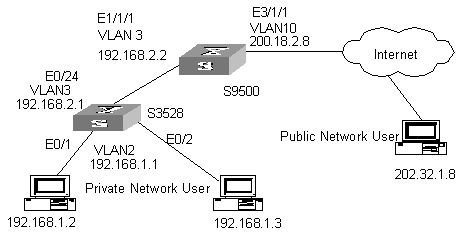
Figure 1-3 Network diagram for NAT
III. Configuration procedure
1) Configure the H3C S3528 switch.
# At the end connecting with the internal network, create VLAN2 and a VALN interface, and configure the IP address.
[H3C] vlan 2
[H3C-vlan2] port ethernet0/1 to ethernet0/2
[H3C-vlan2] quit
[H3C] interface vlan-interface 2
[H3C-vlan-interface2] ip address 192.168.1.1 255.255.255.0
# At the end connecting with the H3C S9500 series routing switch, create VLAN3 and the corresponding VLAN interface, and configure the IP address.
[H3C] vlan 3
[H3C-vlan3] port ethernet0/24
[H3C-vlan3] quit
[H3C] interface vlan-interface 3
[H3C-vlan-interface3] ip address 192.168.2.1 255.255.255.0
2) Configure the H3C S9500 series routing switch.
# At the end connecting with the H3C S3528 switch, create VLAN3 and a VLAN interface, and configure the IP address.
[H3C] vlan 3
[H3C-vlan3] port ethernet1/1/1
[H3C-vlan3] quit
[H3C] interface vlan-interface 3
[H3C-vlan-interface3] ip address 192.168.2.2 255.255.255.0
# At the end connecting with the Internet, create VLAN10 and a VALN interface, and configure the IP address.
[H3C] vlan 10
[H3C-vlan10] port ethernet3/1/1
[H3C-vlan10] quit
[H3C] interface vlan-interface 10
[H3C-vlan-interface10] ip address 200.18.2.8 255.255.255.0
# Configure ACL rule.
[H3C] acl number 2000
[H3C-acl-basic-2000] rule 0 permit any
# Configure a NAT address pool with the identifier of 0.
[H3C] nat address-group 0 200.18.2.3 200.18.2.5
# Associate the ACL with the address pool.
[H3C] interface vlan-interface 10
[H3C-vlan-interface10] nat outbound 2000 address-group 0 slot 3
Chapter 2 URPF Configuration
& Note:
The service processor cards mentioned in the chapter refer to LSBM1NATB boards.
2.1 URPF Overview
Unicast reverse path forwarding (URPF) serves as a safeguard against source address spoofing attacks.
In general, a routing switch routes packets according to their destination. If finding the best routes, routing switches transfer the packets, otherwise, discard the packets.
After URPF is enabled, switches obtain the source addresses and incoming interfaces of packets. Then switches search routes to the destination addresses (that is the source addresses) in routing tables. If the outgoing interfaces are found inconsistent with the incoming interfaces, switches assume the source addresses are forged, and discard the packets.
URPF can prevent malicious attackers from modifying source addresses. The following figure shows the common attack mode.
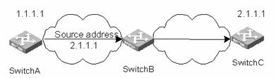
Figure 2-1 Source address spoofing attacks
Forge packets with source address 2.1.1.1 on Switch A, and send a request to Switch B server. Then Switch B responds to the request and sends packets to the address 2.1.1.1 if Switch B does not perform URPF check. The illegal packets can attack both Switch B and Switch C.
2.2 URPF Configuration
The following section describes the URPF configuration tasks:
l Configure packet redirection
l Enable URPF on ports
l Display port configuration information
l Clear URPT statistical counters to zero
Use the urpf enable command to enable URPF for a certain VLAN port and specify the service process board where the port locates. Configure to redirect packets in port view to the service processor card to make data flow reach the service processor card,. Packet direction means you change the direction to forward packets, sending packets to the board’s CPU, other ports, other IP addresses or network segments.
![]() Caution:
Caution:
Because URPF and virtual private LAN service (VPLS) are mutually exclusive, you cannot simultaneously enable URPF and VPLS in the same VLAN interface view.
After enabling URPF on a current VLAN port, you can use the display urpf command to view the configuration. If the enabled and specified network address translation (NAT) server processor card is inserted in the slot, you can also view the statistical data related to URPF on the port.
When a VLAN port with URPF enabled runs for a long time, more statistical data enter the counter. Therefore you need to clear statistical data related to URPF on the port. To clear recording statistics of received and rejected data packets on the port, execute the reset urpf statistic command. As a result, the URPF statistical counter is cleared to zero.
The following table describes URPF configurations.
Table 2-1 Enable URPF on a port and specify the corresponding LSB1NATB boards for handling
|
Item |
Command |
Description |
|
Enter system view |
system-view |
- |
|
Enter Ethernet port view |
interface EthernetX/1/X |
- |
|
Configure packet redirection |
traffic-redirect inbound ip-group { acl-number | acl-name } [ rule rule [ system-index index ] ] { cpu | interface { interface-name | interface-type interface-num } destination-vlan { l2-vpn | l3-vpn } | next-hop ip-addr1 [ ip-addr2 ] | slot slotid vlan vlanid } |
Required. It is recommended to use DMAC+VLAN+IP when you specify the custom flow template. |
|
Quit to system view |
quit |
- |
|
Enter VLAN interface view |
interface vlan-interface vlan-id |
- |
|
Enable URPF on a port |
urpf enable to slot slotid |
Required. Enable URPF in VLAN interface view. Specify corresponding slot of a service processor card to perform URPF check. By default, URPF is disabled. |
|
Display configuration information |
display urpf |
- |
|
Clear URPF statistical counters to zero |
reset urpf statistic |
- |
& Note:
l In access control lists, redirection configuration is only valid for permit action of the rule.
l When redirected to the board’s CPU, packets are not forwarded.
l You can configure the next-hop parameter of the traffic-redirect inbound ip-group command to implement policy routing. Refer to “Packet Redirection” section in “QACL”.
2.3 URPF Configuration Example I
I. Network requirements
What differs from routers is that, for switches, you can enable URPF on VLAN interfaces, and configure only packet redirection on every port. Packets to be checked are sent to the service processor card and then are forwarded or discarded after the system performs URPF procedure on them.
II. Network diagram
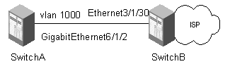
Figure 2-2 Network diagram for URPF configuration
III. Configuration procedure
As for Switch B, assume that the service processor card is installed in slot 5, and normal access boards are installed in slot 3 and 3.
# Configure VLAN 1000.
[H3C] vlan 1000
[H3C-vlan1000] port Ethernet 3/1/30
[H3C-vlan1000] port GigabitEthernet6/1/2
[H3C] int vlan 1000
[H3C-Vlan-interface1000] ip address 10.10.10.1 24
# Configure flow templates. Specify the flow template of the two access boards installed in slot 3 and slot 6 to extract the destination MAC addresses and Ethernet protocol fields of the packets.
[H3C] flow-template user-defined slot 3 dmac 00-00-00 ethernet-protocol
[H3C] flow-template user-defined slot 6 dmac 00-00-00 ethernet-protocol
# Create an ACL of Layer 2.
[H3C]acl number 4000
# Define a rule that permits IP packets whose destination MAC addresses are that of the virtual interface (01-02-03).
[H3C-acl-link-4000] rule 0 permit ip egress 01-02-03 00-00-00
# Configure packet redirecting on the corresponding Ethernet port.
[H3C] interface ethernet 3/1/30
[H3C] flow-template user-defined
[H3C-Ethernet3/1/30] traffic-redirect inbound link-group 4000 slot 5 vlan 1000 [H3C-Ethernet3/1/30] quit
[H3C] interface GigabitEthernet 6/1/2
[H3C-GigabitEthernet6/1/2] flow-template user-defined
[H3C-GigabitEthernet6/1/2] traffic-redirect inbound link-group 4000 slot 5 vlan 1000
[H3C-GigabitEthernet6/1/2] quit
# Enable URPF in VLAN 1000.
[H3C] interface vlan 1000
[H3C-Vlan-Interface1000] urpf enable to slot 5
2.4 URPF Configuration Example II
I. Network requirements
NAT board is placed in slot 5.
Create two virtual interfaces, VLAN interface 1000 and VLAN interface 1001; enable URPF on them and use the NAT service processor card in slot 5 to perform URPF check.
Port Ethernet6/1/1 is a trunk port, permitting packets of VLAN 1000 and VLAN 1001.
It is required that port Ethernet6/1/1 perform URPF check on packets of VLAN 1000 and VLAN 1001.
II. Network diagram
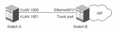
Figure 2-3 Network diagram for URPF
III. Configuration procedure
# Configure VLAN information.
[H3C] vlan 1000
[H3C-vlan1000] vlan 1001
[H3C-vlan1001] quit
[H3C] interface ethernet 6/1/1
[H3C-Ethernet6/1/1]quit
[H3C] vlan 1001
[H3C-vlan1001] quit
[H3C] interface vlan-interface 1000
[H3C-Vlan-interface1000] ip address 10.10.10.1 24
[H3C-Vlan-interface1000] interface vlan-interface 1001
[H3C-Vlan-interface1001] ip address 11.11.11.1 24
# Enable URPF on the VLAN interfaces.
[H3C-Vlan-interface1000] urpf enable to slot 5
[H3C-Vlan-interface1000] interface vlan 1001
[H3C-Vlan-interface1001]urpf enable to slot 5
# Create a layer 2 ACL rule
<H3C> system-view
[H3C] acl number 4000
# Permit the IP packets going into VLAN 1000 and the DMAX should be the virtual interface MAC00e0-fc39-a9b8.
[H3C-acl-link-4000] rule 0 permit ip ingress 1000 egress 00e0-fc39-a9b8 0000-0000-0000
# Permit the IP packets going into VLAN 1001.
[H3C-acl-link-4000] rule 1 permit ip ingress 1001 egress 00e0-fc39-a9b8 0000-0000-0000
# Configure a user-defined flow template.
[H3C] flow-template user-defined slot 6 vlanid ethernet-protocol dmac 00-00-00
# Apply the flow template on port Ethernet 6/1/1 and configure traffic redirection.
[H3C-Ethernet6/1/1] flow-template user-defined
[H3C-Ethernet6/2/1]traffic-redirect inbound link-group 4000 rule 0 slot 5 1000
[H3C-Ethernet6/1/1] traffic-redirect inbound link-group 4000 rule 1 slot 5 1001
Note that the ingress VLAN IDs configured in the rules added to ACL 4000 must be the same as the ones specified when configuring traffic redirection. The trunk port checks URPF by VLAN.
Chapter 3 VPLS Configuration
& Note:
The service processor card mentioned in this chapter refers to the LSBM1VPNB card.
3.1 VPLS Overview
3.1.1 Introduction to VPLS
Today, IP networks have spread throughout the world. And the operators are focusing on using their existing IP networks to provide enterprises with low-cost private networks. Now, an easy-implemented technique called MPLS VPN (multiprotocol label switching VPN) emerges as the times require, which enables the operators to provide arbitrary-rate MPLS-based virtual private network (VPN) services over IP networks.
MPLS VPN services fall into two types: L3 MPLS VPN and L2 MPLS VPN. The latter includes VPLS (virtual private LAN service) and VLL (virtual leased line). VLL only applies to point-to-point networking, while VPLS can apply to multipoint-to-multipoint VPN networking. VPLS provides the operators using point-to-point L2VPN with a better solution. In addition, unlike L3VPN, VPLS does not participate in user's internal routing. Now, operators need only manage and operate a single network to provide multiple kinds of services such as best-effort, L3VPN, L2VPN, traffic-engineering, and distinguished services. This greatly reduces their costs on network construction, operation and maintenance.
With VPLS, users in different areas can be connected with each other through MAN/WAN just like they are in one LAN. S9500 series provide a VPLS solution. This solution uses MPLS-based virtual links as the links of Ethernet bridges and provides transparent transmission LAN services (TLS) over MPLS networks.
The following table lists the acronyms referred in this document:
|
Acronym |
Full name |
|
AC |
Attachment circuit |
|
CE |
Custom edge |
|
FEC |
Forwarding equivalence class |
|
FR |
Frame Relay |
|
NPE |
Network provider edge |
|
PE |
Provider edge router |
|
PW |
Pseudo wires |
|
PHP |
Penultimate hop popping |
|
UPE |
User facing-provider edge |
|
VLL |
Virtual leased line |
|
VPLS |
Virtual private LAN service |
|
VSI |
Virtual switch instance |
|
LSP |
Label switch path |
3.2 Basic VPLS Network Architectures
There are two kinds of VPLS network architectures: PW logical multipoint-to-multipoint connection architecture and hierarchical architecture. Figure 3-1 depicts a VPLS network architecture with PW logical multipoint-to-multipoint connection.
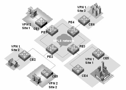
Figure 3-1 VPLS network with PW logical multipoint-to-multipoint connection
As shown in Figure 3-1, VPLS can provide point-to-multipoint connection service like a L3VPN. It can learn MAC addresses and exchange packets between multiple sites. In addition, it keeps the forwarding tables of the individual VPNs independent with each other and allows MAC address overlap between VPNs.
Figure 3-2 depicts a hierarchical VPLS network architecture.
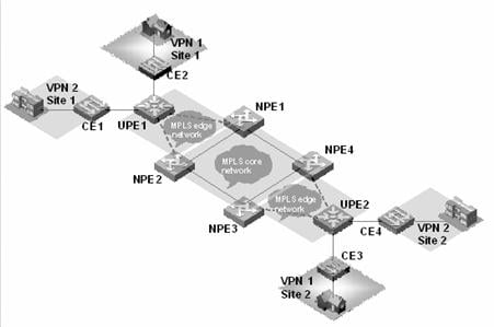
Figure 3-2 Hierarchical VPLS network architecture
As shown in Figure 3-2, the network topology of the VPLS network is hierarchical, and the access range of the network is expansible. The core devices (NPEs) in the core network require high performance because VPN traffic concentrates there, while the edge devices (UPEs) require lower performance because they are mainly used for VPN service access. In addition, you can back up the links between NPEs and UPEs to make the network more robust. The access networks between UPEs and NPEs can be either a MPLS edge network connected by LSP, or a simple Ethernet network for VLAN-VPN user access.
3.3 VPLS Operational Principle
3.3.1 VPLS Basic Transmission Components
As shown in the following figure, the whole VPLS network is just like a huge switch. For each VPN, it sets up PWs between the sites of the VPN on MPLS tunnels and transparently transmits user's layer 2 packets from one site to another through these PWs. In this network, PEs forward packets, learn source MAC addresses, create MAC forwarding entries, and map the MAC addresses to corresponding ACs and PWs. While, the P devices (provider routers, that is, core switches in the backbone network), only implement MPLS forwarding according to MPLS labels without considering layer 2 user data encapsulated in MPLS packets.
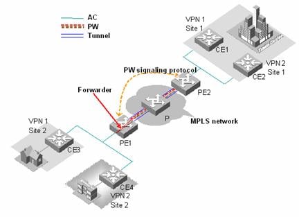
Figure 3-3 L2VPN universal transmission components
The transmission components and their functions in a VPLS network are as follows:
I. Attachment circuit
An attachment circuit (AC) is a virtual connection link between CE and PE. User’s layer 2 and layer 3 data are transmitted to the peer site through AC without any modification.
II. Pseudo wire
A pseudo wire (PW) is a bidirectional virtual connection between two VSIs in a VPN. One PW contains a pair of unidirectional MPLS VCs (virtual circuits). It is established by PW signaling protocol and carried on LSP. For a VPLS system, a PW is just like a directly connected path between local and peer ACs, through which user’s layer 2 data are transmitted transparently.
III. Forwarder
A forwarder is in fact a VPLS forwarding table, it chooses PWs to forward the frames that PEs received from ACs.
IV. Tunnel
A tunnel is a directly connected path between local PE and peer PEs, on which data is transmitted transparently from one PE to another. A tunnel can carry multiple PWs. In general, a tunnel is an MPLS tunnel.
V. Encapsulation
Standard PW encapsulation formats and technique are adopted when packets are transmitted over PWs. VPLS packets carried on PWs have two encapsulation modes: Tagged and Raw.
VI. PW signaling
PW signaling (pseudo wire signaling) protocol on which VPLS bases is used to establish and maintain PW. It can also be used to automatically discover peer PEs of VSIs. Currently, PW signaling protocol includes label distribution protocol (LDP) and border gateway protocol (BGP).
VII. Service quality
Service quality maps priority information in the headers of user’s layer 2 packets and QoS information carried by VSI instances to QoS priority of the public network before the forwarding of the packets. This feature generally requires the MPLS network to support traffic-engineering.
As shown in Figure 3-3, CE3 transmits uplink layer 2 packets to PE1 through AC. When PE1 receives the packets, the forwarder chooses PW to forward them. According to PW forwarding entries, the system generates two layers of MPLS labels (private network labels are used to mark the PWs, and public network labels are used to pass through tunnels to PE2) and the Ethernet headers of the public network. After the packets reach PE2 through public network tunnel, the system pops out private network labels (public network labels have already been popped out on P device through PHP). PE2 forwarder chooses an AC to forward layer 2 packets from CE3 to CE1.
3.4 Concepts Related to VPLS
3.4.1 MPLS L2VPN
An MPLS L2VPN is a VPN that transparently transmits user’s layer 2 packets over MPLS network. In user's perspective, an MPLS network is a layer 2 switching network, over which layer 2 connections can be set up among different sites. MPLS L2VPN includes VLL and VPLS.
I. VPLS
This is a kind of point-to-multipoint L2VPN service provided on public networks. VPLS can connect user sites in different areas together over MAN/WAN as if they are in a single LAN.
II. VLL
This is a kind of point-to-point L2VPN service provided on public networks. VLL can connect two sites with each other as if they are directly connected by cables. However, it cannot provide switching directly between multiple points at the service provider level.
3.4.2 CE
It is a user device that is directly connected with a service provider's device.
3.4.3 PE
It is an edge router in backbone network connected with CEs. PE is responsible for VPN service access, it implement packet mapping and forwarding from private networks to public network tunnels, and vice versa. It has two types: UPE and NPE.
I. UPE
It is a user-facing PE device, a kind of convergence device for users to access the VPN.
II. NPE
It is a core PE device, located at the edge of the VPLS core network. It provides VPLS transparent transmission service in the core network.
3.4.4 VSI
Through virtual switch instance (VSI) you can map the actually connected links to each virtual links.
3.5 VPLS Basic Configuration
The following table describes the VPLS configuration tasks:
Table 3-2 VPLS configuration tasks
|
Item |
Command |
Description |
|
Configuring routing protocol for public network |
Refer to the related sections in Operation Manual – Routing Protocol |
Required |
|
Configuring basic MPLS functions |
Refer to chapter 2 Configuring MPLS Basic Functions in Operation Manual – MPLS |
Required |
|
Configuring LDP expansion session peer |
mpls ldp remoter-peer index |
Required |
|
Enabling L2VPN |
mpls l2vpn |
Required |
|
Configuring a VPLS instance |
vsi vsi-name [ static ] |
Required |
|
Configuring an IP address of a peer PE |
peer peer-ip [ vc-id vc-id ] [ upe ] [ { backup-peer | primary-peer } alternatepeer-ip ] [ trans-mode { raw | tagged } ] |
Required |
|
Configuring static MAC addresses |
mac-address { static H-H-H } vsi vsi-name { peer peer-ip | vlan-interface vlan-interface-number } |
Optional |
|
Configuring VLAN for user access and binding VSI |
l2 binding vsi vsi-name [ encapsulation { vlan | ethernet } ] |
Required |
|
Configuring VPLS characteristics |
bandwidth vpn-speed |
Optional |
|
Enabling VLAN VPN on port |
vlan-vpn enable |
Optional |
|
Configuring user-defined flow template |
flow-template user-defined slot slotnum template-info |
Required |
|
Configuring ACL rules |
rule rule-id permit mpls l2label-range ingress any egress any |
Required |
|
Configuring packet redirection |
traffic-redirect inbound link-group { acl-number | acl-name } [ rule rule [ system-index index ] ] | slot slotid vlanid [ join-vlan ] } |
Required |
3.5.1 Configuring Routing Protocols
You must perform some basic routing configuration on your switch such that it can exchange routing information with other P and PE devices. Currently, you can choose the following routing protocols: static routing, routing information protocol (RIP), open shortest path first (OSPF), exterior border gateway protocol (EBGP), and so on. For specific configuration, refer to S9500 Series Routing Switches Operation Manual – Routing Protocol.
3.5.2 Configuring Basic MPLS Functions
Configure basic MPLS functions to create LSP tunnels over public network. For specific configuration, refer to S9500 Series Routing Switches Operation Manual – MPLS.
3.5.3 Configuring LDP Expansion Session Peer
Configure LDP remote peer to set up LDP remote session.
I. Entering the remote-peer mode
Perform the following configuration in system view.
Table 3-3 Enter the remote-peer mode
|
Operation |
Command |
|
Enter the remote-peer mode |
mpls ldp remote-peer index |
|
Remove the remote peer |
undo mpls ldp remote-peer index |
By default, no remote peer exists.
II. Configuring an address for the remote peer
You can specify any LDP-enabled interface address of a remote peer device or the loopback address of a label switch router (LSR) that has advertised its routing information as the address of the remote peer.
Perform the following configuration in remote-peer view.
Table 3-4 Configure an address for the remote peer
|
Operation |
Command |
|
Configure an address for the remote peer |
remote-ip remoteip |
remoteip: IP address for the remote peer. This address is usually the address of the loopback port of the peer.
By default, no IP address is configured for a remote peer.
3.5.4 Enable L2VPN
Enable L2VPN globally before you configure VPLS and VLL; otherwise you cannot configure VPLS and VLL.
Perform the following configuration in system view.
|
Operation |
Command |
|
Enable MPLS L2VPN |
mpls l2vpn |
|
Disable MPLS L2VPN |
undo mpls l2vpn |
By default, MPLS L2VPN is disabled.
3.5.5 Creating a VPLS Instance
I. Specifying a VPLS instance name
Use the vsi command to create a VPLS instance or enter VSI view. When creating a VPLS instance, you must specify a locally unique VPLS instance name, and choose automatic discovery or manual configuration as peer discovery mechanism (currently, only manual configuration is supported).
Table 3-6 Specify a VPLS instance name
|
Operation |
Command |
|
Specify a VPLS instance name |
vsi vsi-name [ static ] [ encapsulation { ethernet | vlan } ] |
|
Remove a VPLS instance or quit the VSI view |
undo vsi vsi-name |
II. Entering VSI-LDP view and configuring VSI-ID
Use the pwsignal command to specify a PW signaling protocol used by VPLS and enter VPLS protocol view.
When you specify Martini as the VPLS connection mode (MPLS L2VPN in Martini mode adopts expanded LDP to send signaling of VC information), you will enter VSI-LDP view at the same time.
Perform the following configuration in VSI view.
Table 3-7 Specify Martini as the VPLS connection mode
|
Operation |
Command |
|
Specify martini as the VPLS connection mode |
pwsignal [ ldp ] |
By default, VPLS adopts Martini mode.
Use the vsi-id command to specify the ID of a VPLS instance. The ID ranges from 1 to 1,024, and must be locally unique.
Perform the following configuration in VSI-LDP view.
Table 3-8 Configure a VPLS instance
|
Operation |
Command |
|
Specify a ID for a VPLS instance |
vsi-id vsi-id |
III. Configuring an IP address of a peer PE
Use the peer command to create a VPLS peer PE contained in an instance. When you create a VPLS peer PE, you must specify an IP address and peer type for the peer PE. By default, the peer type is NPE. When you specify UPE as the peer type, it indicates the peer is a user convergence node UPE in hierarchical VPLS architecture. You can also specify an ID for a VC to the peer, and the ID must be consistent with that of the remote. Multipoint-to-multipoint connections are needed among specified multiple remote peer NPEs, but not needed between UPEs and NPEs.
Perform the following configuration in VSI-LDP view.
Table 3-9 Configure an IP address for a peer PE
|
Operation |
Command |
|
Create a VPLS peer PE contained in the instance |
peer peer-ip [ vc-id vc-id ] [ upe ] [ { backup-peer | primary-peer } alternatepeer-ip ] [ trans-mode { raw | tagged } ] |
|
Remove the specified VPLS peer PE |
undo peer peer-ip |
By default, VC-ID is as big as VSI-ID.
3.5.6 Configuring VLAN for User Access and Binding a VLPS Instance
The port configuration on a VLAN interface differs depending on user access modes. If user gets access by Ethernet, you must enable VLAN-VPN on the access port of the VLAN. If user makes H-VPLS access by VLAN, or user's convergence multi-tenant unit (MTU) makes H-VPLS access by VLAN-VPN, you need not enable VLAN-VPN on the access port; instead, you must configure the port as Trunk, in this case, the VLAN Tag (VLAN ID currently configured for the user) carried in uplink packets must be consistent with that of the VLAN bound with the Trunk. If convergence UPE makes H-VPLS access by LSP, you can bind a VPLS instance to a VLAN containing no port. Additionally, you cannot bind one instance to multiple VLANs.
Perform the following configuration in VLAN interface view.
Table 3-10 Configure VLAN for user access and bind a VPLS instance
|
Operation |
Command |
|
Bind a VPLS instance to a VLAN interface |
l2 binding vsi vsi-name |
|
Remove the binding |
undo l2 binding vsi vsi-name |
![]() Caution:
Caution:
l If any of GVRP, STP and 802.1x protocols is enabled on a port, you cannot enable VLAN VPN on the port;
l If IGMP Snooping is enabled in the VLAN to which the port belongs or if IGMP is enabled on the VLAN interface to which the port belongs, it is not allowed to enable VLAN VPN on the port, and vice versa;
l If a port with enabled VLAN VPN is to join in a VLAN, IGMP Snooping cannot be enabled on the VLAN and IGMP cannot be enabled on its VLAN interfaces;
l The interface of a VLAN with a VPLS instance bound to it cannot be assigned an IP address. Similarly, if the interface of a VLAN is assigned an IP address, you cannot bind VPLS instances to it.
l A VPLS instance can be bound to multiple VLANs. You can bind a VPLS instance to up to eight VLANs.
l It is not allowed to bind VSI instances to VLAN-interface1.
3.5.7 Configuring Static MAC Address
Use the mac-address command to configure a static MAC address for the VPLS instance. The address you configured can be either a MAC address on a local CE or a MAC address on a remote CE.
Table 3-11 Configure static MAC address
|
Operation |
Command |
|
Configure a static MAC address for VPLS instance |
mac-address { static H-H-H } vsi vsi-name { peer peer-ip | vlan-interface vlan-interface-number } |
|
Remove the MAC address |
undo mac-address { static H-H-H } vsi vsi-name |
3.5.8 Enabling VLAN VPN on a Port
![]() Caution:
Caution:
User access mode of VSI determines whether you should enable VLAN-VPN on a port or not. If the access mode is Ethernet, you must enable VLAN-VPN on the access port such that your private VLAN Tag can be properly transferred. If the access mode is VLAN, you must set the access port to Trunk.
Perform the following configuration in Ethernet port view.
Table 3-12 Enable VLAN VPN on a port
|
Operation |
Command |
|
Enable VLAN VPN on a port |
vlan-vpn enable |
|
Disable VLAN VPN on the port |
undo vlan-vpn |
![]() Caution:
Caution:
l If GARP VLAN registration protocol (GVRP), spanning tree protocol (STP) or 802.1x protocol is enabled on a port, VLAN VPN on this port is not allowed to enable.
l If IGMP Snooping is enabled in the VLAN to which the port belongs or if IGMP is enabled on the VLAN interface to which the port belongs, it is not allowed to enable VLAN VPN on the port, and vice versa.
l If a port with enabled VLAN VPN is to join in a VLAN, IGMP Snooping cannot be enabled on the VLAN and IGMP cannot be enabled on its VLAN interfaces.
By default, VLAN VPN is disabled on ports.
3.5.9 Configuring user-defined flow template
Perform the following configuration in system view.
Table 3-13 Configure user-defined flow template
|
Operation |
Command |
|
Define flow template |
flow-template user-defined slot slotnum template-info |
|
Define user flow template in port view |
flow-template user-defined |
|
Remove flow template |
undo flow-template user-defined |
When you define the flow template, the total size of all the elements in the template must be less than 16 bytes.
3.5.10 Configuring ACL rules
Use the following commands to define a Layer 2 ACL.
Perform the following configuration in corresponding views.
Table 3-14 Configure ACL rules
|
Operation |
Command |
|
Enter a Layer 2 ACL view from system view |
acl { number acl-number | name acl-name advanced } [ match-order { config | auto } ] |
|
Define a sub-rule in Layer 2 ACL view |
rule [ rule-id ] { permit | deny } [ cos cos-value | c-tag-cos c-cos-value | exp exp-value | protocol-type | ingress { { source-vlan-id [ to source-vlan-id-end ] | source-mac-addr source-mac-wildcard | c-tag-vlan c-tag-vlanid }* | any } | egress { dest-mac-addr dest-mac-wildcard | any } | s-tag-vlan s-tag-vlanid | time-range name]* |
|
Remove a sub-rule in Layer 2 ACL view |
undo rule rule-id |
|
Remove Layer 2 ACL or all ACLs in system view |
undo acl { number acl-number | name acl-name | all } |
& Note:
Delete related redirection configurations before deleting ACL configuration.
3.5.11 Configuring MPLS redirection
Only VPLS service processor cards can process VPLS services, so it is necessary to redirect the VPLS packets back from the public network side to VPLS service processor card for processing by configuring ACL rules.
Perform the following configuration in Ethernet port view.
Table 3-15 Configure packet redirection on Ethernet port of common interface card
|
Operation |
Command |
|
Configure packet redirection to a specific port of VPLS service processor cards |
traffic-redirect inbound link-group acl-number [ rule rule [ system-index index ] ] slot slotid vlanid [ join-vlan] } |
|
Remove packet redirection |
undo traffic-redirect inbound link-group acl-number [ rule rule ] |
& Note:
After you configure packet redirection, the ports of the public network add to the VALN (specified join-vlan). After you remove packet redirection configuration, the ports exit from the corresponding VLAN.
3.5.12 Configuring VPLS Characteristics
I. Configuring VPN rate limitation
Use the bandwidth command to configure the VPN rate limitation in the range of 64 kbps to 4,194,303 kbps with the increment of 64. After the configuration, the system automatically takes the biggest number that can be exactly divided by 64 and is no more than the setting number as the rate limitation. For example, if you specify the VPN rate limitation to be 200, then the actual is 192, three times of 64. The actually supported rate limitation ranges from 64 kbps to 2,097,152 kbps (included), and if the value you set is above 2,097,152 kbps, no rate limitation is performed. In the instance, the part of traffic beyond this bandwidth restriction is discarded by the system.
Perform the following configuration in VSI-LDP view.
Table 3-16 Configure VPN rate limitation
|
Operation |
Command |
|
Configure VPN rate limitation |
bandwidth vpn-speed |
By default, the VPN rate limitation is 102,400 kbps.
II. Configuring VPN broadcast suppression percentage
Use the broadcast-restrain command to configure the VPN broadcast suppression percentage, which is in the range of 0 to 100. You cannot set the percentage to 0. In the VSI, the part of broadcast traffic (including broadcast, multicast, and unknown unicast) beyond the suppression percentage is discarded.
Perform the following configuration in VSI-LDP view.
Table 3-17 Configure VPN broadcast suppression percentage
|
Operation |
Command |
|
Configure VPN broadcast suppression percentage |
broadcast-restrain restrain-number |
By default, VPN broadcast suppression percentage is 5%.
III. Configuring packet MTU
Use the mtu command to specify the maximum transmission unit (MTU) value for user access packets of this VPLS instance, which is in the range of 128 to 8,192. This MTU value is also the MTU value for PW.
Perform the following configuration in VSI-LDP view.
Table 3-18 Configure packet MTU
|
Operation |
Command |
|
Configure packet mtu for the VPLS instance |
mtu mtu |
By default, MTU is 1,500 Bytes.
IV. Configuring the QoS level
Use the command here to configure the QoS level for the VSI, which is in the range of 0 to 7. When configuring the QoS level, you can either use the QoS mapping table suggested by the protocol, or the user-defined QoS table and set p-p-p-p-p-p-p-p with this command.
Perform the following configuration in VSI-LDP view.
Table 3-19 Configure the QoS level
|
Operation |
Command |
|
Configure the QoS level for the VSI |
qos { 0 | 1 | 2 | 3 | 4 | 5 | 6 | 7 | { user-define-table p p p p p p p p } } |
The default QoS level is 0.
V. Configuring other VPLS characteristics
Perform the following configuration in the corresponding VSI-LDP views.
Table 3-20 Configure other VPLS characteristics
|
Operation |
Command |
|
Define/remove a description of this VPLS instance |
description TEXT undo description |
|
Disable/enable the VPN service of the VPLS instance |
shut undo shut |
|
Configure the maximum number of the MAC addresses in the VPN |
mac-table limit |
3.6 Displaying and Debugging VPLS
VPLS provides various displaying and debugging commands to monitor the LDP session status, tunnel configuration, all LSPs and their status.
Execute the following commands in any view.
|
Operation |
Command |
|
Display a VPLS forwarding table |
display mac-address vsi [ vsi-name ] [ peer peer-address | local | vlan-interface vlan-interface-number ] ] [ dynamic | static ] [ count ] |
|
Display the MPLS-based layer 2 virtual connection information |
display mpls l2vc [ verbose | interface interface-type interface-number | { [ vsi vsi-name ] [ peer peer-ip ] [ up | down | block ] } ] |
|
Display VPLS instance information |
display vsi vsi-name |
Execute the debugging command to debug various LDP messages.
Execute the following commands in user view.
|
Operation |
Command |
|
Enable individual kinds of L2VPN debugging |
debugging mpls l2vpn { advertisement | all | connections | error | event } |
|
Disable individual kinds of L2VPN debugging |
undo debugging mpls l2vpn { advertisement | all | connections | error | event } |
By default, all debugging is disabled.
3.7 VPLS Basic Configuration Example
I. Network requirements
S9500 series switch support all kinds of VPLS architectures and networking. Figure 3-4 shows a simple back-to-back network diagram. Where, two sites of VPN1 connect to port E6/1/48 of the two PEs (PE1 and PE2) respectively. Both PEs are configured with the private VLAN 100 and public VLAN 10 connected through G4/1/1 to implement basic VPLS service.
II. Network diagram
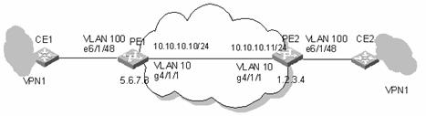
Figure 3-4 Network diagram for VPLS configuration of back-to back PEs
III. Configuration procedure
& Note:
The VPLS service processor card is on slot 5, and the common interface card is on slot 4.
1) Configure PE1
# Configure the Router ID used to advertise OSPF routing information. Generally, the virtual interface address of both MPLS LSI-ID and Loopback0 can be configured with the same IP address.
[PE1] router id 5.6.7.8
# Configure MPLS LSI-ID. Enable MPLS and MPLS LDP globally.
[PE1] mpls lsr-id 5.6.7.8
[PE1] mpls
[PE1] mpls ldp
# Configure a 32-bit Loopback address, which is used to create LSP.
[PE1] interface loopback0
[PE1 -LoopBack0] ip address 5.6.7.8 32
# Configure a public VLAN, add a port to it, configure an IP address for the virtual interface, then, enable MPLS and MPLS LDP on the interface.
[PE1] vlan 10
[PE1-vlan10] port GigabitEthernet 4/1/1
[PE1-vlan10] interface vlan 10
[PE1-vlan-interface10] ip address 10.10.10.10 24
[PE1-vlan-interface10] mpls
[PE1-vlan-interface10] mpls ldp enable
# Configure OSPF to set up routes.
[PE1] ospf
[PE1-ospf-1] area 0
[PE1-ospf-1-area-0.0.0.0] network 5.6.7.8 0.0.0.0
[PE1-ospf-1-area-0.0.0.0] network 10.10.10.10 0.0.0.255
[PE1-ospf-1-area-0.0.0.0] quit
[PE1-ospf-1] import-route direct
[PE1-ospf-1] quit
# Configure a LDP remote peer (PE2) to set up LDP session.
[PE1] mpls ldp remote-peer 1
[PE1-mpls-remote1] remote-ip 1.2.3.4
# Enable L2VPN globally.
[PE1] mpls l2vpn
# Configure a VPLS instance and VSI-ID (VPN-ID). Enter VSI-LDP view to configure the IP address of PE2.
[PE1] vsi test
[PE1-vsi-test] pwsignal ldp
[PE1-vsi-test-ldp] vsi-id 500
[PE1-vsi-test-ldp] peer 1.2.3.4
[PE1-vsi-test-ldp] quit
# Configure a private VLAN, add a port to it, and bind a VSI instance.
[PE1] vlan 100
[PE1-vlan-100] port Ethernet 6/1/48
[PE1-vlan-100] interface vlan 100
[PE1-vlan-interface100] l2 binding vsi test encapsulation ethernet
# Enable VLAN-VPN on the port of the private network.
[PE1] interface Ethernet 6/1/48
[PE1-Ethernet6/1/48] vlan-vpn enable
# Configure user-defined flow template, and ACL redirection rule to allow for MPLS packets with VPLS labels.
[PE1] flow-template user-defined slot 4 ethernet-protocol vlanid
[PE1] acl number 4000
[PE1-acl-link-4000] rule 0 permit mpls l2label-range ingress any egress any
[PE1-acl-link-4000] quit
# Define user flow template in port view and configure redirection rule to redirect VPLS packets back from the public network to the VPLS service processor card and specify the VLAN ID of the redirection flow.
[PE1] interface GigabitEthernet4/1/1
[PE1-GigabitEthernet4/1/1] flow-template user-defined
[PE1-GigabitEthernet4/1/1] traffic-redirect inbound link-group 4000 rule 0 slot 5 10 join-vlan
2) Configure PE2
# Configure the Router ID used to advertise OSPF routing information. Generally, the virtual interface address of both MPLS LSI-ID and Loopback0 can be configured with the same IP address.
[PE2] router id 1.2.3.4
# Configure mpls lsr-id. Enable MPLS and MPLS LDP globally.
[PE2] mpls lsr-id 1.2.3.4
[PE2] mpls
[PE2] mpls ldp
# Configure a 32-bit Loopback address, which is used to create LSP.
[PE2] interface loopback0
[PE2 -LoopBack0] ip address 1.2.3.4 32
# Configure a public VLAN, add a port to it, configure the IP address for the virtual interface, then, enable MPLS and MPLS LDP on the interface.
[PE2] vlan 10
[PE2-vlan10] port GigabitEthernet 4/1/1
[PE2-vlan10] interface vlan 10
[PE2-vlan-interface10] ip address 10.10.10.11 24
[PE2-vlan-interface10] mpls
[PE2-vlan-interface10] mpls ldp enable
# Configure OSPF to set up routes.
[PE2] ospf
[PE2-ospf-1] area 0
[PE2-ospf-1-area-0.0.0.0] network 1.2.3.4 0.0.0.0
[PE2-ospf-1-area-0.0.0.0] network 10.10.10.11 0.0.0.255
[PE2-ospf-1-area-0.0.0.0] quit
[PE2-ospf-1] import-route direct
[PE2-ospf-1] quit
# Configure a LDP remote peer (PE1) to set up LDP session.
[PE2] mpls ldp remote-peer 1
[PE2-mpls-remote2] remote-ip 5.6.7.8
# Enable L2VPN globally.
[PE2] mpls l2vpn
# Configure a VPLS instance and VSI-ID (VPN-ID). Enter VSI-LDP view to configure the IP address for PE1.
[PE2] vsi test encapsulation ethernet
[PE2-vsi-test] pwsignal ldp
[PE2-vsi-test-ldp] vsi-id 500
[PE2-vsi-test-ldp] peer 5.6.7.8
[PE2-vsi-test-ldp] quit
# Configure a private VLAN, add a port to it, and bind a VSI instance.
[PE2] vlan 100
[PE2-vlan-100] port Ethernet 6/1/48
[PE2-vlan-100] interface vlan 100
[PE2-vlan-interface100] l2 binding vsi test
# Enable VLAN-VPN on the port of the private network.
[PE2] interface Ethernet 6/1/48
[PE2-Ethernet6/1/48] vlan-vpn enable
# Configure user-defined flow template, and ACL redirection rule to allow for MPLS packets with VPLS labels.
[PE2] flow-template user-defined slot 4 ethernet-protocol vlanid
[PE2] acl number 4000
[PE2-acl-link-4000] rule 0 permit mpls l2label-range ingress any egress any
[PE2-acl-link-4000] quit
# Define user flow template in port view and configure redirection rule to redirect VPLS packets back from the public network to the VPLS service processor card and specify the VLAN ID of the redirect flow.
[PE2] interface GigabitEthernet4/1/1
[PE2-GigabitEthernet4/1/1] flow-template user-defined
[PE2-GigabitEthernet4/1/1] traffic-redirect inbound link-group 4000 rule 0 slot 5 10 join vlan
3.8 Troubleshooting VPLS
Symptom 1: PW is not in UP state.
Solution:
l The LSP tunnel over the public network is not set up for the two ends: verify that the route is available on both ends, you can successfully ping the loopback port of the peer, and the LDP session is normal.
l Expansion session is abnormal: verify that the commands used to configure the expansion session are executed on both ends, and the configurations are all right.
l The interface of the private VLAN is not bound with the corresponding VPLS instance, or is DOWN: make sure the interface is UP, or the PW to the UPE is UP.
l The parameters for the peer or the MTU value of the VPLS instance is inconsistent: verify that the MTU value configured for the VPLS instance is consistent on both end, and the VC-ID and transmission mode for the peer is also consistent.
l The VPLS service processor card is not in Normal state: make sure that VPLS service processor card is in Normal state.
Symptom 2: Packets cannot be forwarded.
Solution:
l The service processor card is not in place: use the display device command to verify that the service processor card is in Normal state.
l The service processor card version is inconsistent with the SRP version: verify the service processor card version.
l The flow template and redirection are not correctly configured on the public side: verify the port for the public network is correctly configured.
Symptom 3: Packets get lost during the course of forwarding
Solution:
l Traffic exceeds VPN bandwidth restriction: check the traffic in the VPN and increase VPN bandwidth accordingly.
l Broadcast/multicast/unknown unicast traffic exceeds the bandwidth set by broadcast suppression ratio: check the broadcast suppression of the VPN and the broadcast traffic within the VPN and reconfigure a proper broadcast suppression ratio.
