- Table of Contents
-
- H3C S9500 Series Routing Switches Operation Manual-(V1.01)
- 00-1Cover
- 01-Getting Started Operation
- 02-Port Operation
- 03-VLAN-QinQ Operation
- 04-Network Protocol Operation
- 05-Routing Protocol Operation
- 06-Multicast Protocol Operation
- 07-QACL Operation
- 08-MPLS Operation
- 09-STP Operation
- 10-Security Operation
- 11-Reliability Operation
- 12-System Management Operation
- 13-PoE Operation
- 14-NAT-URPF-VPLS Operation
- 15-Integrated Management Operation
- 16-Appendix
- Related Documents
-
| Title | Size | Download |
|---|---|---|
| 05-Routing Protocol Operation | 771 KB |
Table of Contents
Chapter 1 IP Routing Protocol Overview
1.1 Introduction to IP Route and Routing Table
1.1.1 IP Route and Route Segment
1.1.2 Route Selection through the Routing Table
1.2.1 Routing Protocols and the Preferences of the Corresponding Routes
1.2.2 Supporting Load Sharing and Route Backup
1.2.3 Routes Shared Between Routing Protocols
Chapter 2 Static Route Configuration
2.1 Introduction to Static Route
2.2.1 Configuring a Static Route
2.2.2 Configuring a Default Route
2.2.3 Deleting All the Static Routes
2.3 Displaying and Debugging Static Route
2.4 Typical Static Route Configuration Example
2.5 Troubleshooting Static Route Faults
3.1.2 RIP Enabling and Running
3.2.1 Enabling RIP and Entering RIP View
3.2.2 Enabling RIP on the Specified Network Segment
3.2.3 Configuring Unicast of the Packets
3.2.4 Configuring Split Horizon
3.2.5 Setting Additional Routing Metric
3.2.6 Configuring RIP to Import Routes of Other Protocols
3.2.7 Configuring Route Filtering
3.2.8 Disabling RIP to Receive Host Route
3.2.9 Configuring RIP-2 Route summary Function
3.2.10 Setting the RIP Preference
3.2.11 Specifying RIP Version of the Interface
3.2.13 Configuring RIP-1 Zero Field Check of the Interface Packet
3.2.14 Specifying the Operating State of the Interface
3.2.15 Setting RIP-2 Packet Authentication
3.3 Displaying and Debugging RIP
3.4 Typical RIP Configuration Example
3.5 Troubleshooting RIP Faults
4.1.2 Process of OSPF Route Calculation
4.1.5 Basic Concepts Related to OSPF
4.1.6 OSPF Features Supported by S9500 Series
4.2.4 Specifying an Interface to Run OSPF
4.2.5 Configuring OSPF to Import Routes of Other Protocols
4.2.6 Configuring OSPF to Import Default Routes
4.2.7 Configuring OSPF Route Filtering
4.2.8 Configuring the Route Summary of OSPF
4.2.9 Setting OSPF Route Preference
4.2.10 Configuring OSPF Timers
4.2.11 Configuring the Network Type of the OSPF Interface
4.2.12 Configuring NBMA Neighbors for OSPF
4.2.13 Setting the Interface Priority for DR Election
4.2.14 Configuring an Interval Required for Sending LSU Packets
4.2.15 Configuring the Cost for Sending Packets on an Interface
4.2.16 Configuring to Fill the MTU Field When an Interface Transmits DD Packets
4.2.17 Setting a Shortest Path First (SPF) Calculation Interval for OSPF
4.2.18 Disabling the Interface to Send OSPF Packets
4.2.19 Configuring OSPF Authentication
4.2.20 Configuring OSPF Virtual Link
4.2.21 Configuring Stub Area of OSPF
4.2.22 Configuring NSSA Area of OSPF
4.2.23 Configuring OSPF and Network Management System (NMS)
4.2.24 Resetting the OSPF Process
4.3 Displaying and Debugging OSPF
4.4 Typical OSPF Configuration Example
4.4.1 Configuring DR Election Based on OSPF Priority
4.4.2 Configuring OSPF Virtual Link
4.5 Troubleshooting OSPF Faults
Chapter 5 Integrated IS-IS Configuration
5.1 Introduction to Integrated IS-IS
5.1.1 Terms of IS-IS Routing Protocol
5.1.2 Two-level Structure of IS-IS Routing Protocol
5.1.3 NSAP Structure of IS-IS Routing Protocol
5.1.4 IS-IS Routing Protocol Packets
5.2 Configuring Integrated IS-IS
5.2.1 Enabling IS-IS and Entering the IS-IS View
5.2.2 Setting Network Entity Title
5.2.3 Enabling IS-IS on the Specified Interface
5.2.4 Setting Priority for DIS Election
5.2.6 Setting Interface Circuit Level
5.2.7 Configuring IS-IS to Import Routes of Other Protocols
5.2.8 Configuring IS-IS Route Filtering
5.2.9 Configuring IS-IS Routing Leak
5.2.10 Setting IS-IS Route Summary
5.2.11 Setting to Generate Default Route
5.2.12 Setting the Preference of IS-IS Protocol
5.2.13 Configuring IS-IS Route Metric Type
5.2.14 Setting IS-IS Link State Routing Cost
5.2.15 Configuring IS-IS Timers
5.2.16 Setting IS-IS Authentication
5.2.17 Setting the Mesh Group of the Interface
5.2.18 Setting Overload Flag Bit
5.2.19 Setting to Discard the LSPs with Checksum Errors
5.2.20 Setting to Log the Peer Changes
5.2.21 Setting LSP Refreshment Interval
5.2.22 Setting Lifetime of LSP
5.2.23 Setting Parameters Related to SPF
5.2.24 Enabling/Disabling IS-IS Packet Transmission
5.2.25 Resetting All the IS-IS Data Structure
5.2.26 Resetting the Specified IS-IS Peer
5.3 Displaying and Debugging Integrated IS-IS
5.4 Typical Integrated IS-IS Configuration Example
6.2.2 Configuring Basic Features for BGP Peer
6.2.3 Configuring application features of a BGP peer (group)
6.2.4 Configuring Route Filtering of a Peer (group)
6.2.5 Configuring Network Routes for BGP Distribution
6.2.6 Configuring the Interaction between BGP and IGP
6.2.7 Configuring BGP Route Aggregation
6.2.8 Configuring BGP Route Filtering
6.2.9 Configuring BGP Route Dampening
6.2.10 Configuring BGP Preference
6.2.12 Configuring the Local Preference
6.2.14 Comparing the MED Routing Metrics from the Peers in Different ASs
6.2.15 Configuring BGP Route Reflector
6.2.16 Configuring BGP AS Confederation Attribute
6.2.17 Configuring BGP Load Balancing
6.2.18 Clearing BGP Connection
6.3 Displaying and Debugging BGP
6.4 Typical BGP Configuration Examples
6.4.1 Configuring BGP AS Confederation Attribute
6.4.2 Configuring BGP Route Reflector
Chapter 7 IP Routing Policy Configuration
7.1 Introduction to IP Routing Policy
7.1.2 Routing Policy Application
7.2 Configuring IP Routing Policy
7.2.1 Configuring a Route-policy
7.2.3 Configuring the AS Path List
7.2.4 Configuring a Community Attribute List
7.2.5 Applying Route Policy on Imported Routes
7.2.6 Applying Route Policy on Received or Advertised Routes
7.3 Displaying and Debugging the Routing Policy
7.4 Typical IP Routing Policy Configuration Example
7.4.1 Configuring to Filter the Received Routing Information
7.5 Troubleshooting Routing Policy
Chapter 8 Route Capacity Configuration
8.1 Introduction to Route Capacity Configuration
8.1.2 Setting the Maximum Number of Route Entries Supported by the System
8.1.3 Setting the Maximum Number of VRFs Supported by the System
Chapter 9 Recursive Routing Configuration
9.1 Recursive Routing Overview
9.1.1 Configuring Recursive Routing
Chapter 1 IP Routing Protocol Overview
& Note:
A router that is referred to in the following or its icon represents a generalized router or an S9500 series routing switch running routing protocols. To improve readability, this will not be described in the other parts of the manual.
For the configuration of VPN instance, refer to the MPLS module in H3C S9500 Series Routing Switches Operation Manual.
1.1 Introduction to IP Route and Routing Table
1.1.1 IP Route and Route Segment
Routers are implemented for route selection in the Internet. A router works in the following way: The router selects an appropriate path (through a network) according to the destination address of the packet it receives and forwards the packet to the next router. The last router in the path is responsible for submitting the packet to the destination host.
In Figure 1-1, R stands for a router. A packet sent from Host A to Host C should go through two routers and the packet is transmitted through two hops. Therefore, when a node (router) is connected to another node through a network, they are in the same route segment and are deemed as adjacent in the Internet. That is, the adjacent routers refer to two routers connected to the same network. The number of route segments between a router and hosts in the same network counted as zero. In Figure 1-1, the bold arrows represent these route segments. Which physical links comprise which route segment is not a concern of a router however.
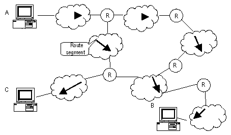
Figure 1-1 The concept of route segment
As the networks may have different sizes, the segment lengths connected between two different pairs of routers are also different. The number of route segments multiplies a weighted coefficient can serve as a weighted measurement for the actual length of the signal transmission path.
If a router in a network is regarded as a node and a route segment in the Internet is regarded as a link, message routing in the Internet works in a similar way as the message routing in a conventional network. Message routed through the shortest route may not always be the optimal route. For example, routing through three high-speed LAN route segments may be much faster than that through two low-speed WAN route segments.
1.1.2 Route Selection through the Routing Table
The key for a router to forward packets is the routing table. Each router saves a routing table in its memory, and each entry of this table specifies the physical port of the router through which the packet is sent to a subnet or a host. Therefore, it can reach the next router via a particular path or reach a destination host via a directly connected network.
A routing table has the following key entries:
l Destination address: It is used to identify the destination IP address or the destination network of an IP packet.
l Network mask: Combined with the destination address, it is used to identify the network address of the destination host or router. If the destination address is ANDed with the network mask, you will get the address of the network segment where the destination host or router is located. For example, if the destination address is 129.102.8.10, the address of the network where the host or the router with the mask 255.255.0.0 is located will be 129.102.0.0. It is made up of several consecutive "1"s, which can also be expressed in the dotted decimal format.
l Output interface: It indicates an interface through which an IP packet should be forwarded.
l Next hop address: It indicates the IP address of the next router that an IP packet will pass through.
l Priority added to the IP routing table for a route: There may be different next hops to the same destination. These routes may be discovered by different routing protocols, or they can just be the static routes configured manually. The one with the highest priority (the smallest numerical value) will be selected as the current optimal route.
l Path cost: Cost to forward data over the route.
According to different destinations, the routes can be divided into:
l Subnet route: The destination is a subnet.
l Host route: The destination is a host
In addition, according to whether the network of the destination host is directly connected to the router, there are the following types of routes:
l Direct route: The router is directly connected to the network where the destination resides.
l Indirect route: The router is not directly connected to the network where the destination resides.
In order to limit the size of the routing table, an option is available to set a default route. All the packets that fail to find the suitable entry will be forwarded through this default route.
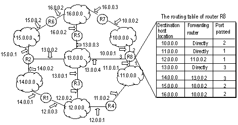
In a complicated Internet as shown in Figure 1-2, the number in each network is the network address, and R stands for a router. The router R8 is directly connected with three networks, so it has three IP addresses and three physical ports, and its routing table is shown in the diagram below:
The H3C S9500 Series Routing Switches (hereinafter referred to as S9500 series) support the configuration of a series of dynamic routing protocols such as RIP, OSPF, IS-IS and BGP, as well as the static routes. In addition, the running switch will automatically obtain some direct routes according to the port state and user configuration.
1.2 Routing Management Policy
For S9500 series, you can configure manually the static route to a specific destination, and configure dynamic routing protocol to interact with other routers on the network. The routing algorithm can also be used to discover routes. For the configured static routes and dynamic routes discovered by the routing protocol, the S9500 series implement unified management. That is, the static routes configured by the user are managed together with the dynamic routes discovered by the routing protocol. The static routes and the routes learned or configured by different routing protocols can also be shared with each other.
1.2.1 Routing Protocols and the Preferences of the Corresponding Routes
Different routing protocols (as well as the static configuration) may generate different routes to the same destination, but not all these routes are optimal. In fact, at a certain moment, only one routing protocol can determine a current route to a specific destination. Thus, each of these routing protocols (including the static configuration) is set with a preference, and when there are multiple routing information sources, the route discovered by the routing protocol with the highest preference will become the current route. Routing protocols and the default preferences (the smaller the value is, the higher the preference is) of the routes learned by them are shown in Table 1-1.
In the table, 0 indicates a direct route. 255 indicates any route from unreliable sources.
Table 1-1 Routing protocols and the default preferences for the routes learned by them
|
Routing protocol or route type |
The preference of the corresponding route |
|
DIRECT |
0 |
|
OSPF |
10 |
|
IS-IS |
15 |
|
STATIC |
60 |
|
RIP |
100 |
|
OSPF ASE |
150 |
|
OSPF NSSA |
150 |
|
IBGP |
256 |
|
EBGP |
256 |
|
UNKNOWN |
255 |
Apart from direct routing, IBGP and EBGP, the preferences of various dynamic routing protocols can be manually configured to meet the user requirements. In addition, the preferences for individual static routes can be different.
1.2.2 Supporting Load Sharing and Route Backup
I. Load sharing
The S9500 series support static equivalent route, permitting to configure multiple routes that reach the same destination and use the same precedence. After you configured static equivalent routes, a packet can reach the same destination through multiple different paths, whose precedence levels are equal. When there is no route that can reach the same destination with a higher precedence, the multiple routes will be adopted. Thus, the router will forward the packets to the destination through these paths according to a certain algorithm so as to implement load sharing.
For the same destination, a specified routing protocol may find multiple different routes with the same precedence and different next hops. If the routing protocol has the highest precedence among all active routing protocols, these multiple routes will be regarded as currently valid routes. Thus, load sharing of IP traffic is ensured in terms of routing protocols.
By far, S9500 series support eight routes to implement load sharing.
II. Route backup
The S9500 series support route backup. When the main route fails, the system will automatically switch to a backup route to improve the network reliability.
In order to achieve static route backup, the user can configure multiple routes to the same destination according to actual situations. One of the routes has the highest precedence and is called as main route. The other routes have descending precedence levels and are called as backup routes. Normally, the router sends data via main route. When the line fails, the main route will hide itself and the router will choose one from the left routes as a backup route whose precedence is higher than others’ to send data. In this way, the switchover from the main route to the backup route is implemented. When the main route recovers, the router will restore it and re-select route. As the main route has the highest precedence, the router still chooses the main route to send data. This process is the automatic switchover from the backup route to the main route.
1.2.3 Routes Shared Between Routing Protocols
As the algorithms of various routing protocols are different, different protocols may generate different routes, thus bringing about the problem of how to resolve the differences when different routes are generated by different routing protocols. The S9500 series support the import of routes discovered by one routing protocol into another. Each protocol has its own route importing mechanism. For details, refer to the description about "Importing an External Route" in the operation manual of the corresponding routing protocol.
Chapter 2 Static Route Configuration
2.1 Introduction to Static Route
2.1.1 Static Route
A static route is a special route configured manually by an administrator. You can set up an interconnecting network with the static route configuration. The problem for such configuration is when a fault occurs to the network, the static route cannot change automatically to steer away from the node causing the fault, if without the help of an administrator.
In a relatively simple network, you only need to configure the static routes to make the router work normally. The proper configuration and usage of the static route can improve the network performance and ensure the bandwidth of the important applications.
All the following routes are static routes:
l Reachable route: A normal route is of this type. That is, the IP packet is sent to the next hop via the route marked by the destination. It is a common type of static routes.
l Unreachable route: When a static route to a destination has the "reject" attribute, all the IP packets to this destination will be discarded, and the source host will be informed that the destination is unreachable.
l Blackhole route: If a static route to a destination has the “blackhole” attribute, the outgoing interface of this route is the Null 0 interface regardless of the next hop address, and any IP packets addressed to this destination are dropped without notifying the source host.
The attributes "reject" and "blackhole" are usually used to control the range of reachable destinations of this router, and help troubleshooting the network.
2.1.2 Default Route
A default route is a special route. You can configure a default route using a static route. Some dynamic routing protocols can also generate default routes, such as OSPF and IS-IS.
In brief, a default route is used only when no suitable routing table entry is matched. That is, when no proper route is found, the default route is used. In a routing table, the default route is in the form of the route to the network 0.0.0.0 (with the mask 0.0.0.0). You can see whether the default route has been set by executing the display ip routing-table command. If the destination address of a packet fails in matching any entry of the routing table, the router will select the default route to forward this packet. If there is no default route and the destination address of the packet fails in matching any entry in the routing table, this packet will be discarded, and an internet control message protocol (ICMP) packet will be sent to the originating host to inform that the destination host or network is unreachable.
2.2 Configuring Static Route
Static Route Configuration includes:
l Deleting All the Static Routes
2.2.1 Configuring a Static Route
Perform the following configurations in system view.
Table 2-1 Configure a static route
|
Operation |
Command |
|
Add a static route |
ip route-static [ vpn-instance vpn-instance-name-list ] ip-address { mask | mask-length } { interface-type interface-number | [ vpn-instance vpn-instance-name ] gateway-address } [ preference preference-value ] [ reject | blackhole ] |
|
Delete a static route |
undo ip route-static [ vpn-instance vpn-instance-name-list ] ip-address { mask | mask-length } { interface-type interface-number | [ vpn-instance vpn-instance-name ] gateway-address } [ preference preference-value ] [ reject | blackhole ] |
The parameters are explained as follows:
l IP address and mask
The IP address and mask are in a dotted decimal format. As "1"s in the 32-bit mask is required to be consecutive, the dotted decimal mask can also be replaced by the mask-length (which refers to the digits of the consecutive "1"s in the mask).
l Next hop address and NULL interface
When configuring a static route, you can specify the gateway-address to decide the next hop address, depending on the actual conditions.
In fact, for all the routing entries, the next hop address must be specified. When IP layer transmits an IP packet, it will first search the matching route in the routing table according to the destination address of the packet. Only when the next hop address of the route is specified can the link layer find the corresponding link layer address, and then forward the packet according to this address.
The packets sent to NULL interface, a kind of virtual interface, will be discarded at once. This can decrease the system load.
l Preference
Depending on the configuration of preference, you can achieve different route management policies. For example, to implement load sharing, you can specify the same preference for multiple routes to the same destination network. To implement route backup, you can specify different preferences for them.
l Other parameters
The attributes reject and blackhole respectively indicate the unreachable route and the blackhole route.
2.2.2 Configuring a Default Route
Perform the following configurations in system view.
Table 2-2 Configure a default route
|
Operation |
Command |
|
Configure a default route |
ip route-static 0.0.0.0 { 0.0.0.0 | 0 } { interface-type interface-number | gateway-address } [ preference value ] [ reject | blackhole ] |
|
Delete a default route |
undo ip route-static 0.0.0.0 { 0.0.0.0 | 0 } [ interface-type interface-number | gateway-address ] [ preference value ] |
The meanings of parameters in the command are the same as those of the static route.
2.2.3 Deleting All the Static Routes
You can use the undo ip route-static command to delete one static route. The S9500 series also provide the following command for you to delete all static routes at one time, including the default routes.
Perform the following configuration in system view.
Table 2-3 Delete all static routes
|
Operation |
Command |
|
Delete all static routes |
delete static-routes all |
|
Delete all static routes of the VPN |
delete vpn-instance vpn-instance-name static-routes all |
2.3 Displaying and Debugging Static Route
After the above configuration, execute the display command in any view to display the running of the static route configuration, and to verify the effect of the configuration.
Table 2-4 Display and debug the routing table
|
Operation |
Command |
|
Display routing table summary |
display ip routing-table |
|
Display routing table details |
display ip routing-table verbose |
|
Display the detailed information of a specific route |
display ip routing-table ip-address [ mask ] [ longer-match ] [ verbose ] |
|
Display the route information in the specified address range |
display ip routing-table ip-address1 mask1 ip-address2 mask2 [ verbose ] |
|
Display the route filtered through the specified basic access control list (ACL) |
display ip routing-table acl { acl-number | acl-name } [ verbose ] |
|
Display the route information that is filtered through the specified ip prefix list |
display ip routing-table ip-prefix ip-prefix-number [ verbose ] |
|
Display the routing information discovered by the specified protocol |
display ip routing-table protocol protocol [ inactive | verbose ] |
|
Display the tree routing table |
display ip routing-table radix |
|
Display the statistics of the routing table |
display ip routing-table statistics |
|
Display the routing information about the VPN instance |
display ip routing-table vpn-instance vpn-instance-name |
2.4 Typical Static Route Configuration Example
I. Network requirements
As shown in Figure 2-1, the masks of all the IP addresses are 255.255.255.0. It is required that all the hosts or S9500 series routing switches can be interconnected in pairs by static route configuration.
II. Network diagram
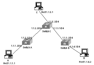
Figure 2-1 Network diagram for the static route configuration example
III. Configuration procedure
# Configure the static route for Switch A
[Switch A] ip route-static 1.1.3.0 255.255.255.0 1.1.2.2
[Switch A] ip route-static 1.1.4.0 255.255.255.0 1.1.2.2
[Switch A] ip route-static 1.1.5.0 255.255.255.0 1.1.2.2
# Configure the static route for Switch B
[Switch B] ip route-static 1.1.2.0 255.255.255.0 1.1.3.1
[Switch B] ip route-static 1.1.5.0 255.255.255.0 1.1.3.1
[Switch B] ip route-static 1.1.1.0 255.255.255.0 1.1.3.1
# Configure the static route for Switch C
[Switch C] ip route-static 1.1.1.0 255.255.255.0 1.1.2.1
[Switch C] ip route-static 1.1.4.0 255.255.255.0 1.1.3.2
# Configure the default gateway of the Host A to be 1.1.1.2
# Configure the default gateway of the Host B to be 1.1.4.1
# Configure the default gateway of the Host C to be 1.1.5.2
Then, all the hosts or switches in the figure can be interconnected in pairs.
2.5 Troubleshooting Static Route Faults
Symptom:
The switch is not configured with the dynamic routing protocol and both the physical status and the link layer protocol status of the interface is Up, but the IP packets cannot be forwarded normally.
Solution:
l Use the display ip routing-table protocol static command to view whether the configured static route is correct and in effect.
Chapter 3 RIP Configuration
3.1 Introduction to RIP
Routing Information Protocol (RIP) is a relatively simple interior gateway protocol (IGP), which is mainly applied to small scale networks.
It is easy to implement RIP. You can configure and maintain RIP more easily than OSPF and IS-IS, so RIP still has a wide application in actual networking.
3.1.1 RIP Operation Mechanism
I. RIP basic concepts
RIP is a kind of Distance-Vector (D-V) algorithm-based protocol and exchanges routing information via UDP packets.
It employs Hop Count to measure the distance to the destination host, which is called Routing Cost. In RIP, the hop count from a router to its directly connected network is 0, and that to a network which can be reached through another router is 1, and so on. To restrict the time to converge, RIP prescribes that the cost value is an integer ranging from 0 to 15. The hop count equal to or exceeding 16 is defined as infinite, that is, the destination network or the host is unreachable.
To improve the performance and avoid route loop, RIP supports Split Horizon and allows importing the routes discovered by other routing protocols.
II. RIP route database
Each router running RIP manages a route database, which contains routing entries to all the reachable destinations in the network. These routing entries contain the following information:
l Destination address: IP address of a host or a network.
l Next hop address: The interface address of the next router that an IP packet will pass through for reaching the destination.
l Output interface: The interface through which the IP packet should be forwarded.
l Cost: The cost for the router to reach the destination, which should be an integer in the range of 0 to 16.
l Timer: Duration from the last time that the routing entry is modified till now. The timer is reset to 0 whenever a routing entry is modified.
III. RIP timer
In RFC1058, RIP is controlled by the following timers: Period update, Timeout and Garbage-Collection.
l Period Update is triggered periodically to send all RIP routes to all neighbors.
l If the RIP route is not updated (a router receives the update packets from the neighbor) when the Timeout timer expires, this route is regarded as unreachable. The cost is set to 16.
l If the Garbage-Collection timer expires, and the unreachable route receives no update packet from the same neighbor, the route will be completely deleted from the routing table.
l By default, the values of Period Update and Timeout timers are 30 seconds and 180 seconds respectively. The value of Garbage-collection timer is four times that of Period Update timer: 120 seconds.
3.1.2 RIP Enabling and Running
The following section describes the procedure:
l If RIP is enabled on a router for the first time, the router will broadcast or multicast the request packet to the adjacent routers. Upon receiving the request packet, the RIP on each adjacent router responds with a packet conveying its local routing table.
l After receiving the response packets, the router, which has sent the request, will modify its own routing table. At the same time, the router sends trigger modification packets to its adjacent routers running RIP and broadcasts modification information, following split horizon mechanism. After receiving trigger modification packets, the adjacent routers send trigger modification packets to their respective adjacent routers. As a result, each router can obtain and maintain the latest routing information.
l RIP broadcasts its routing table to the adjacent routers every 30 seconds. The adjacent routers will maintain their own routing table after receiving the packets and will select an optimal route, and then advertise the modification information to their respective adjacent network so as to make the updated route globally known. Furthermore, RIP uses the timeout mechanism to handle the out-timed routes so as to ensure the real-timeliness and validity of the routes.
RIP has become one of the actual standards of transmitting router and host routes by far. It can be used in most of the campus networks and the regional networks that are simple yet extensive. For larger and more complicated networks, RIP is not recommended.
3.2 Configuring RIP
1) RIP basic configuration
RIP basic configuration includes:
l Enabling RIP
l Enabling RIP on specified network
If the link, which does not support broadcast or multicast packets, runs RIP, you need to configure RIP to send any packet to the specified destination, establishing RIP neighbors correctly.
In NBMA link networking through a Frame Relay sub-interface and others, to ensure the routing information can be correctly transmitted, you possibly need to disable split horizon.
2) RIP route management
You can make the following configurations for RIP to advertise and receive routing information:
l Setting additional routing metric
l Configuring RIP to import routers of other protocols
l Configuring RIP route filtering
l Enabling/disabling host route receiving by the router
l Configuring RIP-2 route summary
3) RIP configuration
l Configuring the RIP precedence
l Configuring RIP timers
l Configuring zero field check for RIP-1 packets
l Specifying RIP version of the interface
4) Configuration related to security
You can select the following configurations to improve RIP security during exchanging routing information, or control the area to transmit RIP packets.
l Setting RIP-2 packet authentication
l Specifying the operating state of the interface
3.2.1 Enabling RIP and Entering RIP View
Perform the following configurations in system view.
Table 3-1 Enable RIP and enter RIP view
|
Operation |
Command |
|
Enable RIP and enter the RIP view |
rip |
|
Disable RIP |
undo rip |
By default, RIP is not enabled.
3.2.2 Enabling RIP on the Specified Network Segment
To flexibly control RIP operation, you can enable RIP on the specified network segment so that the corresponding ports can receive and send RIP packets.
Perform the following configurations in RIP view.
Table 3-2 Enable RIP Interface
|
Operation |
Command |
|
Enable RIP on the specified network |
network network-address |
|
Disable RIP on the specified network |
undo network network-address |
Note that after the RIP task is enabled, you should also specify its operating network segment, for RIP only operates on the interface on the specified network segment. For an interface that is not on the specified network segment, RIP does not receive or send routes on it, nor forwards its interface route, as if this interface does not exist at all. network-address is the address of the enabled or disabled network, and it can also be configured as the IP network address of respective interfaces.
When a command network is used for an address, you can enable the network address of the port, which also includes the subnet addresses. For example, for network 129.102.1.1, you can see network 129.102.0.0 either using display current-configuration or using display rip command.
By default, RIP is disabled on all the interfaces after it is started up.
3.2.3 Configuring Unicast of the Packets
Usually, RIP sends packets using broadcast or multicast addresses. It exchanges routing information with non-broadcasting networks in unicast mode.
Perform the following configuration in RIP view.
Table 3-3 Configure unicast of the packets
|
Operation |
Command |
|
Configure unicast of the packets |
peer ip-address |
|
Cancel unicast of the packets |
undo peer ip-address |
By default, RIP does not send any packets to any unicast addresses.
It should be noted that a peer should also be restricted by rip work, rip output, rip input and network when transmitting packets.
3.2.4 Configuring Split Horizon
Split horizon means that the route received via an interface will not be sent via this interface again. To some extent, the split horizon is necessary for reducing routing loop. But in some special cases, split horizon must be disabled so as to ensure the correct advertisement of the routes at the cost of efficiency. For example, split horizon is disabled on a NBMA network if it runs RIP.
Perform the following configuration in interface view.
Table 3-4 Configure Split Horizon
|
Operation |
Command |
|
Enable split horizon |
rip split-horizon |
|
Disable split horizon |
undo rip split-horizon |
By default, split horizon of the interface is enabled.
3.2.5 Setting Additional Routing Metric
Additional routing metric is the input or output routing metric added to an RIP route. It does not change the metric value of the route in the routing table, but adds a specified metric value when the interface receives or sends a route.
Perform the following configuration in interface view.
Table 3-5 Set additional routing metric
|
Operation |
Command |
|
Set the additional routing metric of the route when the interface receives an RIP packet |
rip metricin value |
|
Disable the additional routing metric of the route when the interface receives an RIP packet |
undo rip metricin |
|
Set the additional routing metric of the route when the interface sends an RIP packet |
rip metricout value |
|
Disable the additional routing metric of the route when the interface sends an RIP packet |
undo rip metricout |
By default, the additional routing metric added to the route when RIP sends a packet is 1. The additional routing metric when RIP receives the packet is 0 by default.
& Note:
The metricout configuration takes effect only on the RIP routes learnt by the router and RIP routes generated by the router itself. That is, it has no effect on the routes imported to RIP by other routing protocols.
3.2.6 Configuring RIP to Import Routes of Other Protocols
RIP allows users to import the route information of other protocols into the RIP routing table.
RIP can import the routes of Direct, Static, OSPF, IS-IS and BGP, etc.
Perform the following configuration in RIP view.
Table 3-6 Configure RIP to import routes of other protocols
|
Operation |
Command |
|
Configure RIP to import routes of other protocols |
import-route protocol [ cost value | route-policy route-policy-name ]* |
|
Cancel the imported routing information of other protocols |
undo import-route protocol |
|
Set the default routing metric |
default cost value |
|
Restore the default routing metric |
undo default cost |
By default, RIP does not import the route information of other protocols.
If you do not specify the routing metric when importing a route, the default routing metric 1 is used.
3.2.7 Configuring Route Filtering
The router provides the route filtering function. You can configure the filter policy rules through specifying the ACL and IP-prefix for route import and advertisement. Besides, to import a route, the RIP packet of a specific router can also be received by designating a neighbor router.
Perform the following configuration in RIP view.
I. Configuring RIP to filter the received routes
Table 3-7 Configure RIP to filter the received routes
|
Operation |
Command |
|
Configure RIP to filter the received routing information advertised by the specified address |
filter-policy gateway ip-prefix-name import |
|
Cancel filtering the received routing information advertised by the specified address |
undo filter-policy gateway ip-prefix-name import |
|
Configure RIP to filter the received global routing information |
filter-policy { acl-number | ip-prefix ip-prefix-name } import |
|
Cancel filtering the received global routing information |
undo filter-policy { acl-number | ip-prefix ip-prefix-name } import |
II. Configuring RIP to filter the routes advertised by RIP
Table 3-8 Configure RIP to filter the advertised routes
|
Operation |
Command |
|
Configure RIP to filter the advertised routing information |
filter-policy { acl-number | ip-prefix ip-prefix-name } export [ routing-protocol ] |
|
Cancel filtering the advertised routing information |
undo filter-policy { acl-number | ip-prefix ip-prefix-name } export [ routing-protocol ] |
By default, RIP does not filter the received and advertised routing information.
& Note:
l The filter-policy import command filters the RIP routes received from its neighbors, and the routes that fail to pass the filter will not be added to the routing table, and will not be advertised to the neighbors.
l The filter-policy export command filters all the advertised routes, including routes imported by the import-route command, and RIP routes learned from the neighbors.
l If the filter-policy export command does not specify which route to be filtered, then all the routes imported by the import-route command and the advertised RIP routes will be filtered.
3.2.8 Disabling RIP to Receive Host Route
In some special cases, the router can receive a lot of host routes, and these routes are of little help in route addressing but consume a lot of network resources. Routers can be configured to reject host routes by using the undo host-route command.
Perform the following configuration in RIP view.
Table 3-9 Enable/disable host route receiving
|
Operation |
Command |
|
Enable the route to receive host route |
host-route |
|
Disable the router from receiving host route |
undo host-route |
By default, the router receives the host route.
3.2.9 Configuring RIP-2 Route summary Function
The so-called route summary means that different subnet routes in the same natural network can be aggregated into one natural mask route for transmission when they are sent to the outside (i.e. other network). Route summary can be performed to reduce the routing traffic on the network as well as to reduce the size of the routing table.
RIP-1 only sends the route with natural mask, that is, it always sends routes in the route summary form. RIP-2 supports subnet mask and classless interdomain routing. To advertise all the subnet routes, the route summary function of RIP-2 can be disabled.
Perform the following configuration in RIP view.
Table 3-10 Enable/disable RIP-2 route summary function
|
Operation |
Command |
|
Enable the route summary function of RIP-2 |
summary |
|
Disable the route summary function of RIP-2 |
undo summary |
By default, RIP-2 route summary is enabled.
3.2.10 Setting the RIP Preference
Each kind of routing protocol has its own preference, by which the routing policy will select the optimal one from the routes of different protocols. The greater the preference value is, the lower the preference becomes. The preference of RIP can be set manually.
Perform the following configuration in RIP view.
Table 3-11 Set the RIP Preference
|
Operation |
Command |
|
Set the RIP Preference |
preference value |
|
Restore the default value of RIP preference |
undo preference |
By default, the preference of RIP is 100.
3.2.11 Specifying RIP Version of the Interface
RIP has two versions, RIP-1 and RIP-2. You can specify the version of the RIP packets processed by the interface.
RIP-1 broadcasts the packets. RIP-2 can transmit packets by both broadcast and multicast. By default, multicast is adopted for transmitting packets. In RIP-2, the multicast address is 224.0.0.9. The advantage of transmitting packets in the multicast mode is that the hosts not operating RIP in the same network can avoid receiving RIP broadcast packets. In addition, this mode can also make the hosts running RIP-1 avoid incorrectly receiving and processing the routes with subnet mask in RIP-2. When an interface is running in RIP-2 broadcast mode, the RIP-1 packets can also be received.
Perform the following configuration in interface view:
Table 3-12 Specify RIP version of the interface
|
Operation |
Command |
|
Specify the RIP version as RIP-1 for the interface |
rip version 1 |
|
Specify the RIP version as RIP-2 for the interface |
rip version 2 [ broadcast | multicast ] |
|
Restore the default RIP version running on the interface |
undo rip version |
By default, the interface receives and sends the RIP-1 packets. It will transmit packets in multicast mode when the interface RIP version is set to RIP-2.
3.2.12 Configuring RIP Timers
As mentioned previously, RIP has three timers: Period update, Timeout and Garbage-collection. Modification of these timers affects RIP convergence speed.
Perform the following configuration in RIP view.
Table 3-13 Configure RIP timers
|
Operation |
Command |
|
Configure RIP timers |
timers { update update-timer-length | timeout timeout-timer-length } * |
|
Restore the default settings of RIP timers |
undo timers { update | timeout } * |
The modification of RIP timers is validated immediately.
By default, the values of Period Update and Timeout timers are 30 seconds and 180 seconds respectively. The value of Garbage-collection timer is four times that of Period Update timer: 120 seconds.
In fact, you may find that the timeout time of Garbage-collection timer is not fixed. If Period Update timer is set to 30 seconds, Garbage-collection timer might range from 90 to 120 seconds.
Before RIP completely deletes an unreachable route from the routing table, it advertises the route by sending four Period Update packets with route metric of 16, so as to acknowledge all the neighbors that the route is unreachable. As routes cannot always become unreachable at the point when a new period starts, the actual value of Garbage-collection timer is three to four times that of Period Update timer.
& Note:
You must consider network performance when adjusting RIP timers, and configure all the routers that are running RIP, so as to avoid unnecessary traffic or network jitter.
3.2.13 Configuring RIP-1 Zero Field Check of the Interface Packet
According to the RFC1058, some fields in the RIP-1 packet must be 0, and they are called zero fields. Therefore, when an interface version is set as RIP-1, the zero field check should be performed on the packet. But if the value in the zero filed is not zero, processing will be refused. As there is no zero field in the RIP-2 packet, this configuration is invalid for RIP-2.
Perform the following configuration in RIP view.
Table 3-14 Configure zero field check of the interface packet
|
Operation |
Command |
|
Configure zero field check on the RIP-1 packet |
checkzero |
|
Disable zero field check on the RIP-1 packet |
undo checkzero |
By default, RIP-1 performs zero field check on the packet.
3.2.14 Specifying the Operating State of the Interface
In interface view, you can specify the operating state of RIP on the interface. For example, whether RIP operates on the interface, namely, whether RIP update packets are sent and received on the interface. In addition, whether an interface sends or receives RIP update packets can be specified separately.
Perform the following configuration in interface view.
Table 3-15 Specify the operating state of the interface
|
Operation |
Command |
|
Enable the interface to run RIP |
rip work |
|
Disable the interface to run RIP |
undo rip work |
|
Enable the interface to receive RIP update packet |
rip input |
|
Disable the interface to receive RIP update packet |
undo rip input |
|
Enable the interface to send RIP update packet |
rip output |
|
Disable the interface to send RIP update packet |
undo rip output |
The undo rip work command and the undo network command have similar but not all the same functions. Neither of the two commands configures an interface to receive or send RIP route. The difference also exists. RIP still advertises the routes of the interface applying the undo rip work command. However, other interfaces will not forward the routes of the interface applying the undo network command. It seems that the interface is removed.
In addition, rip work is functionally equivalent to both rip input and rip output commands.
By default, all interfaces except loopback interfaces both receive and transmit RIP update packets.
3.2.15 Setting RIP-2 Packet Authentication
RIP-1 does not support packet authentication. But when the interface operates RIP-2, the packet authentication can be configured.
RIP-2 supports two authentication modes: Simple authentication and MD5 authentication. MD5 authentication uses two packet formats: One follows RFC1723 and the other follows the RFC2082.
The simple authentication does not ensure security. The authentication key not encrypted is sent together with the packet, so the simple authentication cannot be applied to the case with high security requirements.
Perform the following configuration in Interface view:
Table 3-16 Set RIP-2 packet authentication
|
Operation |
Command |
|
Configure RIP-2 simple authentication key |
rip authentication-mode simple password-string |
|
Perform usual MD5 authentication on RIP-2 packets |
rip authentication-mode md5 usual key-string |
|
Perform nonstandard-compatible MD5 authentication on RIP-2 packets |
rip authentication-mode md5 nonstandard key-string key-id |
|
Disable RIP-2 packet authentication |
undo rip authentication-mode |
Before configuring MD5 authentication, you must configure MD5 type. The usual packet format follows RFC1723 and the nonstandard follows RFC2082.
3.3 Displaying and Debugging RIP
After the above configuration, execute the display command in any view to display the running of the RIP configuration, and to verify the effect of the configuration. Execute the debugging command in user view to debug the RIP module. Execute the reset command in RIP view to reset the system configuration parameters of RIP.
Table 3-17 Display and debug RIP
|
Operation |
Command |
|
Display the current RIP running state and configuration information. |
display rip |
|
Enable the RIP packet debugging information |
debugging rip packet |
|
Disable the RIP packet debugging information |
undo debugging rip packet |
|
Enable the debugging of RIP receiving packets |
debugging rip receive |
|
Disable the debugging of RIP receiving packets |
undo debugging rip receive |
|
Enable the debugging of RIP sending packet |
debugging rip send |
|
Disable the debugging of RIP sending packet |
undo debugging rip send |
|
Reset the system configuration parameters of RIP |
reset |
3.4 Typical RIP Configuration Example
I. Network requirements
As shown in Figure 3-1, the S9500 series routing switch C connects to the subnet 117.102.0.0 through the Ethernet port. The Ethernet ports of the S9500 series routing switches A and Switch B are respectively connected to the network 155.10.1.0 and 196.38.165.0. Switch C, Switch A and Switch B are connected via Ethernet 110.11.2.0. Correctly configure RIP to ensure that Switch C, Switch A and Switch B can interconnect with each other.
II. Network diagram
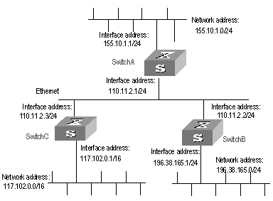
Figure 3-1 Network diagram for RIP configuration
III. Configuration procedure
& Note:
The following configuration only shows the operations related to RIP. Before performing the following configuration, make sure the Ethernet link layer can work normally.
1) Configure Switch A
# Configure RIP
[Switch A] rip
[Switch A-rip] network 110.11.2.0
[Switch A-rip] network 155.10.1.0
2) Configure Switch B
# Configure RIP
[Switch B] rip
[Switch B-rip] network 196.38.165.0
[Switch B-rip] network 110.11.2.0
3) Configure Switch C
# Configure RIP
[Switch C] rip
[Switch C-rip] network 117.102.0.0
[Switch C-rip] network 110.11.2.0
3.5 Troubleshooting RIP Faults
Symptom: The S9500 series cannot receive the update packets when the physical connection to the peer routing device is normal.
Solution: RIP does not operate on the corresponding interface (for example, the undo rip work command is executed) or this interface is not enabled through the network command. The peer routing device is configured to be in the multicast mode (for example, the rip version 2 multicast command is executed) but the multicast mode has not been configured on the corresponding interface of the local switch.
Chapter 4 OSPF Configuration
4.1 OSPF Overview
4.1.1 Introduction to OSPF
Open Shortest Path First (OSPF) is an Interior Gateway Protocol based on the link state developed by IETF. At present, OSPF version 2 (RFC2328) is used, which is available with the following features:
l Applicable scope: It can support networks in various sizes and can support several hundreds of routers at maximum.
l Fast convergence: It can transmit the update packets instantly after the network topology changes so that the change is synchronized in the AS.
l Loop-free: Since the OSPF calculates routes with the shortest path tree algorithm according to the collected link states, it is guaranteed that no loop routes will be generated from the algorithm itself.
l Area partition: It allows the network of AS to be divided into different areas for the convenience of management so that the routing information transmitted between the areas is abstracted further, hence to reduce the network bandwidth consumption.
l Equal-cost multi-route: Support multiple equal-cost routes to a destination.
l Routing hierarchy: OSPF has a four-level routing hierarchy. It prioritizes the routes to be intra-area, inter-area, external type-1, and external type-2 routes.
l Authentication: It supports the interface-based packet authentication so as to guarantee the security of the route calculation.
l Multicast transmission: Support multicast address to receive and send packets.
4.1.2 Process of OSPF Route Calculation
The routing calculation process of the OSPF protocol is as follows:
l Each OSPF-capable router maintains a Link State Database (LSDB), which describes the topology of the whole AS. According to the network topology around itself, each router generates a Link State Advertisement (LSA). The routers on the network transmit the LSAs among them by transmitting the protocol packets to each others. Thus, each router receives the LSAs of other routers and all these LSAs compose its LSDB.
l LSA describes the network topology around a router, so the LSDB describes the network topology of the whole network. Routers can easily transform the LSDB to a weighted directed graph, which actually reflects the topology architecture of the whole network. Obviously, all the routers get a graph exactly the same.
l A router uses the SPF algorithm to calculate the shortest path tree with itself as the root, which shows the routes to the nodes in the autonomous system. The external routing information is the leave node. A router, which advertises the routes, also tags them and records the additional information of the autonomous system. Obviously, the routing tables obtained by different routers are different.
Furthermore, to enable individual routers to broadcast their local state information to the entire AS, any two routers in the environment should establish adjacency between them. In this case, however, the changes that any router takes will result in multiple transmissions, which are not only unnecessary but also waste the precious bandwidth resources. To solve this problem, “Designated Router” (DR) is defined in the OSPF. Thus, all the routers only send information to the DR for broadcasting the network link states in the network. Thereby, the number of router adjacent relations on the multi-access network is reduced.
OSPF supports interface-based packet authentication to guarantee the security of route calculation. Also, it transmits and receives packets by IP multicast (224.0.0.5 and 224.0.0.6).
4.1.3 OSPF Packets
OSPF uses five types of packets:
l Hello Packet:
It is the commonest packet, which is periodically sent by a router to its neighbor. It contains the values of some timers, DR, BDR and the known neighbor.
l Database Description (DD) Packet:
When two routers synchronize their databases, they use the DD packets to describe their own LSDBs, including the digest of each LSA. The digest refers to the HEAD of LSA, which uniquely identifies the LSA. This reduces the traffic size transmitted between the routers, since the HEAD of a LSA only occupies a small portion of the overall LSA traffic. With the HEAD, the peer router can judge whether it already has had the LSA.
l Link State Request (LSR) Packet:
After exchanging the DD packets, the two routers know which LSAs of the peer routers are lacked in the local LSDBs. In this case, they will send LSR packets requesting for the needed LSAs to the peers. The packets contain the digests of the needed LSAs.
l Link State Update (LSU) Packet:
The packet is used to transmit the needed LSAs to the peer router. It contains a collection of multiple LSAs (complete contents).
l Link State Acknowledgment (LSAck) Packet
The packet is used for acknowledging the received LSU packets. It contains the HEAD(s) of LSA(s) requiring acknowledgement.
4.1.4 LSA Type
I. Five basic LSA types
As mentioned previously, OSPF calculates and maintains routing information from LSAs. RFC2328 defines five LSA types as follows:
l Router-LSAs: Type-1. Each router generates Router-LSAs, which describe the link state and cost of the local router. Router-LSAs are broadcast within the area where the router is located.
l Network-LSAs: Type-2. DRs on the broadcast network and NBMA network generate Network-LSAs, which describe the link state of the local network. Network-LSAs are broadcast within the area where a DR is located.
l Summary-LSAs: Include Type-3 and Type-4. Area border routers (ABRs) generate Summary-LSAs. Summary-LSAs are broadcast within the area related to the LSA. Each Summary-LSA describes a route (inter-area route) to a certain destination in other areas of this AS. Type-3 Summary-LSAs describe the routes to networks (the destination is network). Type-4 Summary-LSAs describe the routes to autonomous system border routers (ASBRs).
l AS-external-LSAs: or ASE LSA, the Type-5. ASBRs generate AS-external-LSAs, which describe the routes to other ASs. AS-external-LSA packets are transmitted to the whole AS (except Stub areas). AS-external-LSAs can also describe the default route of an AS.
II. Type-7 LSA
RFC1587 (OSPF NSSA Option) adds a new LSA type: Type-7 LSAs.
According to RFC1587, Type-7 LSAs differ from Type-5 LSAs as follows:
l Type-7 LSAs are generated and released within a Not-So-Stubby Area (NSSA). Type-5 LSAs cannot be generated or released within a NSSA.
l Type-7 LSAs can only be released within an NSSA. When Type-7 LSAs reach an ABR, the ABR can convert part routing information of Type-7 LSAs into Type-5 LSAs and releases the information. Type-7 LSAs cannot be directly released to other areas or backbone areas.
4.1.5 Basic Concepts Related to OSPF
I. Router ID
To run OSPF, a router must have a router ID. If no ID is configured, the system will automatically pick an IP address from the IP addresses of the current interfaces as the Router ID. The following introduces how to choose a router ID. If loopback interface addresses exist, the system chooses the Loopback address with the greatest IP address value as the router ID. If no Loopback interface configured, then the address of the physical interface with the greatest IP address value will be the router ID.
II. DR and BDR
l Designated Router (DR)
In multi-access networks, if any two routers establish adjacencies, the same LSA will be transmitted repeatedly, wasting bandwidth resources. To solve this problem, the OSPF protocol regulates that a DR must be elected in a multi-access network and only the DR (and the BDR) can establish adjacencies with other routers in this network. Two non-DR routers or non-BDR routers cannot establish adjacencies and exchange routing information.
You cannot specify the DR in the segment. Instead, DR is elected by all the routers in the segment.
l Backup Designated Router (BDR)
If the DR fails for some faults, a new DR must be elected and synchronized with other routers on the segment. This process will take a relatively long time, during which, the route calculation is incorrect. To shorten the process, BDR is brought forth in OSPF. In fact, BDR is a backup for DR. DR and BDR are elected in the meantime. The adjacencies are also established between the BDR and all the routers on the segment, and routing information is also exchanged between them. After the existing DR fails, the BDR will become a DR immediately.
III. Area
The network size grows increasingly larger. If all the routers on a huge network are running OSPF, the large number of routers will result in an enormous LSDB, which will consume an enormous storage space, complicate the SPF algorithm, and add the CPU load as well. Furthermore, as a network grows larger, the topology becomes more likely to take changes. Hence, the network will always be in “turbulence”, and a great deal of OSPF packets will be generated and transmitted in the network. This will lower the network bandwidth utility. In addition, each change will cause all the routes on the network to recompute the route.
OSPF solves the above problem by partition an AS into different areas. Areas are logical groups of routers. The borders of areas are formed by routers. Thus, some routers may belong to different areas. A router connects the backbone area and a non-backbone area is called Area Border Router (ABR). An ABR can connect to the backbone area physically or logically.
IV. Backbone area and virtual link
l Backbone Area
After the area partition of OSPF, not all the areas are equal. In which, an area is different from all the other areas. Its area-id is 0 and it is usually called the backbone area.
l Virtual link
Since all the areas should be connected to the backbone area, virtual link is adopted so that the physically separated areas can still maintain the logic connectivity to the backbone area.
V. Route summary
An AS is divided into different areas that are interconnected via OSPF ABRs. The routing information between areas can be reduced through route summary. Thus, the size of routing table can be reduced and the calculation speed of the router can be improved. After calculating an intra-area route of an area, the ABR summarizes multiple OSPF routes into an LSA and sends it outside the area according to the configuration of summary.
For example, as shown in Figure 4-1, the Area 19 has three area intra-area routes: 19.1.1.0/24, 19.1.2.0/24 and 19.1.3.0/24. The three routes are summarized into one route 19.1.0.0/16 after you configured route summary. The RTA only generates an LSA, describing the summarized route.
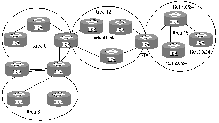
Figure 4-1 Area and route summary
4.1.6 OSPF Features Supported by S9500 Series
The S9500 series support the following OSPF features:
l Support stub areas: OSPF defines stub areas to decrease the overhead when the routers within the area receive ASE routes.
l Support NSSA: OSPF defines NSSA areas, surmounting the restriction of stub areas on topology. NSSA is the abbreviation of Not-So-Stubby Area.
l Support OSPF Multi-Process: A router runs multiple OSPF processes.
l Share the discovered routing information with other dynamic routing protocols: OSPF currently can import static routes and routes of other dynamic routing protocols such as RIP into the autonomous system of the router, or advertise the routing information discovered by OSPF to other routing protocols.
l Authenticator: OSPF provides clear text authenticator and MD5 encryption authenticator to authenticate packets transmitted between neighboring routers in the same area.
l Flexible configuration for the router port parameter: On the router port, you can configure the following OSPF parameters: output cost, Hello packet interval, retransmission interval, port transmission delay, route precedence, invalid time for adjacent routers, packet authentication mode, packet authenticator, and others.
l Virtual connection: Creates and configures virtual connections.
l Abundant debugging information: OSPF provides abundant debugging information, consequently helping users to diagnose failure.
4.2 Configuring OSPF
OSPF configuration needs cooperation among routers: intra-area, area boundary, and AS boundary. If none of OSPF parameters is configured, their default settings apply. In this case, sent and received packets are not authenticated, and an individual interface does not belong to the area of any AS. When reconfiguring a default parameter on one router, make sure that the same change is made on all other involved routers.
In various configurations, you must first enable OSPF, specify the interface and area ID before configuring other functions. But the configuration of the functions related to the interface is not restricted by whether the OSPF is enabled or not. It should be noted that after OSPF is disabled, the OSPF-related interface parameters also become invalid.
OSPF configuration includes:
1) OSPF basic configuration
l Configuring Router ID
l Enabling OSPF
l Entering the OSPF area view
l Enabling OSPF on the specified network
2) Configuration related to OSPF route
l Configuring OSPF to import routes of other protocols
l Configuring OSPF to import default routes
l Configuring OSPF route filtering
l Configuring OSPF route convergence
3) Some OSPF configurations
l Configuring OSPF precedence
l Setting the interface priority for DR election
l Configuring OSPF timers
l Configuring the time for the interface to send LSU packets
l Configuring the cost for sending packets on an interface
l Configuring the network type on the OSPF interface
l Configuring NBMA neighbors for OSPF
l Configuring to fill the MTU field when an interface transmits DD packets
l Setting an SPF calculation interval for OSPF
4) Configurations related to OSPF networking
l Configuring OSPF authentication
l Prohibit OSPF packet receiving/sending
l Configuring OSPF virtual link
l Configuring Stub area of OSPF
l Configuring NSSA of OSPF
5) Configuration related to specific applications
l Configuring OSPF and network management system
6) Others
l Resetting the OSPF process
4.2.1 Configuring Router ID
Router ID is a 32-bit unsigned integer in IP address format that uniquely identifies a router within an AS. Router ID can be configured manually. If router ID is not configured, the system will select the IP address of an interface automatically. When you do that manually, you must guarantee that the IDs of any two routers in the AS are unique. A common undertaking is to set the router ID to be the IP address of an interface on the router.
Perform the following configuration in system view.
|
Operation |
Command |
|
Configure router ID |
router id router-id |
|
Remove the router ID |
undo router id |
To ensure stability of OSPF, the user should determine the division of router IDs and manually configure them when planning the network.
4.2.2 Enabling OSPF
Perform the following configuration in system view.
|
Operation |
Command |
|
Enable OSPF and enter OSPF view |
ospf [ process-id [ router-id router-id | vpn-instance vpn-instance-name]] |
|
Disable one or all OSPF processes |
undo ospf [ process-id ] |
By default, OSPF is disabled.
When enabling OSPF, pay attention to the following points:
l The default OSPF process ID is 1. If no process ID is specified in the command, the default one is adopted.
l If a router is running multiple OSPF processes, you are recommended to use router-id in the command to specify different router IDs for different processes.
4.2.3 Entering OSPF Area View
OSPF divides an AS into different areas or logical groups of routers.
Perform the following configuration in OSPF view.
Table 4-3 Enter OSPF area view
|
Operation |
Command |
|
Enter OSPF area view |
area area-id |
|
Delete an OSPF area |
undo area area-id |
The area-id parameter identifies an area. It can be a decimal integer in the range of 0 to 4,294,967,295, or in the format of IP address. Regardless of how it is specified, it is displayed in the format of IP address.
Note that when you configure OSPF routers in the same area, you should apply most configuration data to the whole area. Otherwise, the neighboring routers cannot exchange information. This may even block routing information or create routing loops.
4.2.4 Specifying an Interface to Run OSPF
After using the ospf command to enable OSPF in system view, you must specify the network to run OSPF. An ABR router can be in different areas, while a network segment can only belong to an area. That is, you must specify a specific area for each port running OSPF.
Perform the following configuration in OSPF area view.
Table 4-4 Specifying an interface to run OSPF
|
Operation |
Command |
|
Specify an interface to run OSPF |
network ip-address ip-mask |
|
Disable OSPF on the interface |
undo network ip-address ip-mask |
The ip-mask argument is IP address wildcard shielded text (similar to the complement of the IP address mask).
4.2.5 Configuring OSPF to Import Routes of Other Protocols
The dynamic routing protocols on the router can share the routing information. As far as OSPF is concerned, the routes discovered by other routing protocols are always processed as the external routes of AS. In the import-route commands, you can specify the route cost type, cost value and tag to overwrite the default route receipt parameters (refer to “Configuring parameters for OSPF to import external routes”).
The OSPF uses the following four types of routes (ordered by priority):
l Intra-area route
l Inter-area route
l External route type 1
l External route type 2
Intra-area and inter-area routes describe the internal AS topology whereas the external routes describe how to select the route to the destinations beyond the AS.
The external routes type-1 refers to the imported IGP routes (such as static route and RIP). Since these routes are more reliable, the calculated cost of the external routes is the same as the cost of routes within the AS. Also, such route cost and the route cost of the OSPF itself are comparable. That is, cost to reach the external route type 1 = cost to reach the corresponding ASBR from the local router + cost to reach the destination address of the route from the ASBR.
The external routes type-2 refers to the imported EGP routes. Since these routes have lower credibility, OSPF assumes that the cost spent from the ASBR to reach the destinations beyond the AS is greatly higher than that spent from within the AS to the ASBR. So in route cost calculation, the former is mainly considered, that is, the cost spent to reach the external route type 2 = cost spent to the destination address of the route from the ASBR. If the two values are equal, then the cost of the router to the corresponding ASBR will be considered.
I. Configuring OSPF to import external routes
Perform the following configuration in OSPF view.
Table 4-5 Configure OSPF to import external routes
|
Operation |
Command |
|
Configure OSPF to import routes of other protocols |
import-route protocol [ cost value | type value | tag value | route-policy route-policy-name ]* |
|
Cancel importing routing information of other protocols |
undo import-route protocol |
By default, OSPF will not import the routing information of other protocols. For an imported route, type is 2, cost is 1, and tag is 1 by default.
The routes that can be imported include Direct, Static, rip, is-is, and bgp. In addition, the routes of other OSPF processes can also be imported.
& Note:
l It is recommended to configure the imported route type, cost and tag for the import-route command simultaneously. Otherwise, the later configuration will overwrite the former configuration.
l After you configured the import-route command on the OSPF router to import external routing information, this OSPF router becomes an ASBR.
II. Configuring the maximum number of imported exterior routes
Table 4-6 Configure the maximum number of imported exterior routes
|
Operation |
Command |
|
Configure the maximum number of imported exterior routes |
import-route-limit num |
|
Restore the default value of the maximum number of imported exterior routes |
undo import-route-limit |
By default, the maximum number of imported exterior routes is 20K.
III. Configuring parameters for OSPF to import external routes
When the OSPF imports the routing information discovered by other routing protocols in the autonomous system, some additional parameters need configuring, such as default route cost and default tag of route distribution. Route tag can be used to identify the protocol-related information. For example, OSPF can use it to identify the AS number when receiving BGP.
Perform the following configuration in OSPF view.
Table 4-7 Configure parameters for OSPF to import external routes
|
Operation |
Command |
|
Configure the default cost for the OSPF to import external routes |
default cost value |
|
Restore the default cost for the OSPF to import external routes |
undo default cost |
|
Configure the default tag for the OSPF to import external routes |
default tag tag |
|
Restore the default tag for the OSPF to import external routes |
undo default tag |
|
Configure the default type of external routes that OSPF will import |
default type { 1 | 2 } |
|
Restore the default type of the external routes imported by OSPF |
undo default type |
By default, the type of imported route is type-2, the cost is 1 and the tag is 1 for a imported route.
IV. Configuring the default interval and number for OSPF to import external routes
OSPF can import the external routing information and broadcast it to the entire autonomous system. Importing routes too often and importing too many external routes at one time will greatly affect the performance of the device. Therefore it is necessary to specify the default interval and number for the protocol to import external routes.
Perform the following configuration in OSPF view.
Table 4-8 Configure the default interval and number for OSPF to import external routes
|
Operation |
Command |
|
Configure the default interval for OSPF to import external routes |
default interval seconds |
|
Restore the default interval for OSPF to import external routes |
undo default interval |
|
Configure the upper limit to the routes that OSPF imports at a time |
default limit routes |
|
Restore the default upper limit to the external routes that can be imported at a time |
undo default limit |
By default, the interval for importing external routes is 1 second. The upper limit to the external routes imported is 1000 at a time.
4.2.6 Configuring OSPF to Import Default Routes
By default, there are no default routes in a common OSPF area (either a backbone area or a non-backbone area). Besides, the import-route command cannot be used to import the default route.
Use the default-route-advertise command to generate and advertise a default route in an OSPF route area. Note the following when you use this command:
l If you use the default-route-advertise command on an ASBR or ABR of a common OSPF area, the system generates a Type-5 LSA, advertising the default route in the OSPF route area.
l If you use the default-route-advertise command on an ASBR or ABR of an NSSA, the system generates a Type-7 LSA, advertising the default route in the NSSA.
l This command is invalid for a stub area or a totally stub area.
l For an ASBR, the system generates the corresponding Type-5 LSA or Type-7 LSA by default when a default route existed in the routing table.
l For an ABR, the system will generate a Type-5 LSA or Type-7 LSA no matter whether there is a default route in the routing table.
l The broadcasting scope of Type-5 LSA or Type-7 LSA advertising the default route is the same as that of the common Type-5 LSA or Type-7 LSA.
Perform the following configuration in OSPF view.
Table 4-9 Configure OSPF to import the default route
|
Operation |
Command |
|
Import the default route to OSPF |
default-route-advertise [ always | cost value | type type-value | route-policy route-policy-name ]* |
|
Remove the imported default route |
undo default-route-advertise [ always | cost | type | route-policy ]* |
By default, OSPF does not import the default route.
If you use the always keyword of this command, the system will generate a Type-5 or Type-7 LSA no matter whether there is default route in the routing table. Be cautious that the always keyword is only valid for an ASBR.
Because OSPF does not calculate the LSAs it generated during SPF calculation, there is no default route in the OSPF route on this router. To ensure the correct routing information, you should configure to import the default route on the router only connected to the external network.
& Note:
l After the default-route-advertise command is configured on the OSPF router, this router becomes an ASBR. For the OSPF router, the default-route-advertise and import-route commands have the similar effect.
l For the ABR or ASBR in the NSSA area, the default-route-advertise and nssa default-route-advertise commands have the same effect.
4.2.7 Configuring OSPF Route Filtering
Perform the following configuration in OSPF view.
I. Configuring OSPF to filter the received routes
Table 4-10 Enable OSPF to filter the received routes
|
Operation |
Command |
|
Disable filtering the received global routing information |
filter-policy { acl-number | ip-prefix ip-prefix-name | gateway ip-prefix-name } import |
|
Cancel filtering the received global routing information |
undo filter-policy { acl-number | ip-prefix ip-prefix-name | gateway ip-prefix-name } import |
By default, OSPF will not filter the received routing information.
II. Configuring filtering the routes imported to OSPF
Use the filter-policy export command to configure the ASBR router to filter the external routes imported to OSPF. This command is only valid for the ASBR router.
Table 4-11 Enable OSPF to filter the imported routes of other routing protocols
|
Operation |
Command |
|
Enable OSPF to filter the routes advertised by other routing protocols |
filter-policy { acl-number | ip-prefix ip-prefix-name } export [ routing-protocol ] |
|
Disable OSPF to filter the advertised routes by other routing protocols |
undo filter-policy { acl-number | ip-prefix ip-prefix-name } export [ routing-protocol ] |
By default, OSPF does not receive the routes advertised by other routing protocols.
& Note:
l The filter-policy import command only filters the OSPF routes of this process received from the neighbors, and routes that cannot pass the filter will not be added to the routing table. This command only takes effect on ABR.
l The filter-policy export command only takes effect on the routes imported by the import-route command. If you configure the switch with only the filter-policy export command, but without configuring the import-route command to import other external routes (including OSPF routes of different process), then the filter-policy export command does not take effect.
l If the filter-policy export command does not specify which type of route is to be filtered, it takes effect on all routes imported by the local device using the import-route command.
III. Configuring filtering of received Type-3 LSAs
Use the following command to configure route filtering between OSPF areas.
Table 4-12 Configure filtering of received Type-3 LSAs
|
Operation |
Command |
|
Enable an OSPF area to filter received Type-3 LSAs |
filter-policy { acl-number | ip-prefix ip-prefix-name } import |
|
Disable an OSPF area from filtering received Type-3 LSAs |
undo filter-policy { acl-number | ip-prefix ip-prefix-name } import |
By default, the OSPF area does not filter received Type-3 LSAs.
IV. Configuring filtering of Type-3 LSAs advertised to other areas
Table 4-13 Configure filtering of Type-3 LSAs advertised to other areas
|
Operation |
Command |
|
Enable an OSPF area to filter Type-3 LSAs advertised to other areas |
filter-policy { acl-number | ip-prefix ip-prefix-name } export |
|
Disable an OSPF area from filtering Type-3 LSAs advertised to other areas |
undo filter-policy { acl-number | ip-prefix ip-prefix-name } export |
By default, an OSPF area does not filter Type-3 LSAs advertised to other areas.
& Note:
The filter-policy import/export command filters only locally originated Type-3 LSAs, and does not filter Type-3 LSAs received from neighbors. This command is valid on ABR only.
4.2.8 Configuring the Route Summary of OSPF
I. Configuring the route summary of OSPF area
Route summary means that ABR can aggregate information of the routes of the same prefix and advertise only one route to other areas. An area can be configured with multiple aggregate segments, thereby OSPF can summarize them. When the ABR transmits routing information to other areas, it will generate Sum_net_Lsa (type-3 LSA) per network. If some continuous networks exist in this area, you can use the abr-summary command to summarize these segments into one segment. Thus, the ABR only needs to send an aggregated LSA, and all the LSAs in the range of the aggregate segment specified by the command will not be transmitted separately. This can reduce the LSDB size in other areas.
Once the aggregated segment of a certain network is added to the area, all the internal routes of the IP addresses in the range of the aggregated segment will no longer be separately advertised to other areas. Only the route summary of the whole aggregated network will be advertised. But if the range of the segment is restricted by the keyword not-advertise, the route summary of this segment will not be advertised. This segment is represented by IP address and mask.
Route summary can take effect only when it is configured on ABRs.
Perform the following configuration in OSPF area view.
Table 4-14 Configure the route summary of OSPF area
|
Operation |
Command |
|
Configure route summary of OSPF area |
abr-summary ip-address mask [ advertise | not-advertise ] |
|
Cancel route summary of OSPF area |
undo abr-summary ip-address mask |
By default, route summary is disabled on ABRs.
II. Configuring summarization of imported routes by OSPF
OSPF of the S9500 series supports route summary of imported routes.
Perform the following configurations in OSPF view.
Table 4-15 Configure summarization of imported routes by OSPF
|
Operation |
Command |
|
Configure summarization of imported routes by OSPF |
asbr-summary ip-address mask [ not-advertise | tag value ] |
|
Remove summarization of routes imported into OSPF |
undo asbr-summary ip-address mask |
By default, summarization of imported routes is disabled.
After the summarization of imported routes is configured, if the local router is an autonomous system border router (ASBR), this command summarizes the imported Type-5 LSAs in the summary address range. When NSSA is configured, this command will also summarize the imported Type-7 LSA in the summary address range.
If the local router works as an area border router (ABR) and a router in the NSSA, this command summarizes Type-5 LSAs transformed from Type-7 LSAs. If the router is not the router in the NSSA, the summarization is disabled.
4.2.9 Setting OSPF Route Preference
Since maybe multiple dynamic routing protocols are running on one router concurrently, the problem of route sharing and selection between various routing protocols occurs. The system sets a preference for each routing protocol, which will be used in tie-breaking in case different protocols discover the same route.
Perform the following configuration in OSPF view.
Table 4-16 Set OSPF route preference
|
Operation |
Command |
|
Configure a preference for OSPF for comparing with the other routing protocols |
preference [ ase ] preference |
|
Restore the default protocol preference |
undo preference [ ase ] |
By default, the OSPF preference is 10, and that of the imported external routing protocol is 150.
4.2.10 Configuring OSPF Timers
I. Setting the interval for Hello packet transmission
Hello packets are a kind of most frequently used packets, which are periodically sent to the adjacent router for discovering and maintaining the adjacency, and for electing DR and BDR. The user can set the Hello timer.
According to RFC2328, the consistency of Hello intervals between network neighbors should be kept. The Hello interval value is in inverse proportion to the route convergence rate and network load.
Perform the following configuration in interface view.
Table 4-17 Set the Hello interval
|
Operation |
Command |
|
Set the hello interval of the interface |
ospf timer hello seconds |
|
Restore the default hello interval of the interface |
undo ospf timer hello |
|
Set the poll interval on the NBMA interface |
ospf timer poll seconds |
|
Restore the default poll interval |
undo ospf timer poll |
By default, p2p and broadcast interfaces send Hello packets every 10 seconds, and p2mp and nbma interfaces send Hello packets every 30 seconds.
II. Setting a dead timer for the neighboring routers
The dead timer of neighboring routers refers to the interval in which a router will regard the neighboring router as dead if no Hello packet is received from it. The user can set a dead timer for the neighboring routers.
Perform the following configuration in interface view.
Table 4-18 Set a dead timer for the neighboring routers
|
Operation |
Command |
|
Configure a dead timer for the neighboring routers |
ospf timer dead seconds |
|
Restore the default dead interval of the neighboring routers |
undo ospf timer dead |
By default, the dead interval for the neighboring routers of p2p or broadcast interfaces is 40 seconds and that for the neighboring routers of p2mp or nbma interfaces is 120 seconds.
Note that both hello and dead timer will restore to the default values after the user modify the network type.
III. Setting an interval for LSA retransmission between neighboring routers
If a router transmits a Link State Advertisements (LSA) to the peer, it requires the acknowledgement packet from the peer. If it does not receive the acknowledgement packet within the retransmit time, it will retransmit this LSA to the neighbor. The value of retransmit is user-configurable.
Perform the following configuration in interface view.
Table 4-19 Set an interval for LSA retransmission between neighboring routers
|
Operation |
Command |
|
Configure the interval of LSA retransmission for the neighboring routers |
ospf timer retransmit interval |
|
Restore the default LSA retransmission interval for the neighboring routers |
undo ospf timer retransmit |
By default, the interval for neighboring routers to retransmit LSAs is 5 seconds.
The value of interval should be bigger than the roundtrip value of a packet.
Note that you should not set the LSA retransmission interval too small. Otherwise, unnecessary retransmission will be caused.
4.2.11 Configuring the Network Type of the OSPF Interface
The route calculation of OSPF is based upon the topology of the adjacent network of the local router. Each router describes the topology of its adjacent network and transmits it to all the other routers.
OSPF divides networks into four types by link layer protocol:
l Broadcast: If Ethernet or FDDI is adopted, OSPF defaults the network type to broadcast.
l Non-Broadcast Multi-access (nbma): If Frame Relay, ATM, HDLC or X.25 is adopted, OSPF defaults the network type to NBMA.
l Point-to-Multipoint (p2mp): OSPF will not default the network type of any link layer protocol to p2mp. A p2mp network is always changed from another type of network. The general undertaking is to change a partially connected NBMA network to p2mp network if the NBMA network is not fully connected.
l Point-to-point (p2p): If PPP, LAPB or POS is adopted, OSPF defaults the network type to p2p.
NBMA means that a network is non-broadcast and multi-accessible. ATM is a typical example for it. The user can configure the polling interval to specify the interval for sending polling hello packets before the adjacency of the neighboring routers is formed.
Set the network type to NBMA if routers not supporting multicast addresses exist in a broadcast network.
Set the interface type to p2mp if not all the routers are directly accessible on an NBMA network.
Change the interface type to p2p if the router has only one peer on the NBMA network.
The differences between NBMA and p2mp are listed below:
l With OSPF, NBMA refers to the networks that are fully connected, non-broadcast and multi-accessible. However, a p2mp network is not necessarily fully connected.
l DR and BDR are required on a NBMA network but not on p2mp network.
l NBMA is the default network type. For example, if ATM is adopted as the link layer protocol, OSPF defaults the network type on the interface to NBMA, regardless of whether the network is fully connected. p2mp is not the default network type. No link layer protocols are regarded as p2mp. You must change the network type to p2mp by force. The commonest undertaking is to change a partially connected NBMA network to a p2mp network.
l NBMA forwards packets by unicast and requires configuring neighbors manually. p2mp forwards packets by multicast.
Perform the following configuration in interface view.
Table 4-20 Configure a network type for an OSPF interface
|
Operation |
Command |
|
Configure the network type on the interface |
ospf network-type { broadcast | nbma | p2mp | p2p } |
|
Restore the default network type of the OSPF interface |
undo ospf network-type |
By default, OSPF determines the network type based on the link layer type. After the interface has been configured with a new network type, the original network type of the interface is removed automatically.
4.2.12 Configuring NBMA Neighbors for OSPF
For an NBMA network, some special configurations are required. Since an NBMA interface on the network cannot discover the adjacent router through broadcasting Hello packets, you must manually specify an IP address for the adjacent router for the interface, and specify whether the adjacent router is eligible for election.
Perform the following configuration in OSPF view.
Table 4-21 Configure the NBMA neighbors for OSPF
|
Operation |
Command |
|
Configure the NBMA neighbors for OSPF |
peer ip-address [ dr-priority dr-priority-number ] |
|
Remove the configured NBMA neighbors |
undo peer ip-address |
By default, the preference for NBMA neighbor is 1.
4.2.13 Setting the Interface Priority for DR Election
On a broadcast or NBMA network, a designated router (DR) and a backup designated router (BDR) must be elected.
The priority of a router interface determines the qualification of the interface in DR election. The router with the priority of 0 cannot be elected as the DR or BDR.
DR is not designated manually. Instead, it is elected by all the routers on the segment. Routers with the priorities larger than 0 in the network are eligible “candidates”. Votes are hello packets. Each router writes the expected DR in the packet and sends it to all the other routers on the segment. If two routers attached to the same segment concurrently declare themselves to be the DR, choose the one with higher priority. If the priorities are the same, choose the one with greater router ID. If the priority of a router is 0, it will not be elected as DR or BDR.
If DR fails due to some faults, the routers on the network must elect a new DR and synchronize with the new DR. The process will take a relatively long time, during which, the route calculation is incorrect. In order to speed up this process, OSPF puts forward the concept of BDR. In fact, BDR is a backup for DR. DR and BDR are elected in the meantime. The adjacencies are also established between the BDR and all the routers on the segment, and routing information is also exchanged between them. When the DR fails, the BDR will become the DR instantly. Since no re-election is needed and the adjacencies have already been established, the process is very short. But in this case, a new BDR should be elected. Although it will also take a quite long period of time, it will not exert any influence upon the route calculation.
Note the following:
l The DR on the network is not necessarily the router with the highest priority. Likewise, the BDR is not necessarily the router with the second highest priority. If a new router is added after DR and BDR election, it is impossible for the router to become the DR even if it has the highest priority.
l DR is based on the router interface in a certain segment. Maybe a router is a DR on one interface, but can be a BDR or DROther on another interface.
l DR election is only required for the broadcast or NBMA interfaces. For the p2p or p2mp interfaces, DR election is not required.
Perform the following configuration in interface view.
Table 4-22 Set the interface priority for DR election
|
Operation |
Command |
|
Configure the interface with a priority for DR election |
ospf dr-priority priority-num |
|
Restore the default interface priority |
undo ospf dr-priority |
By default, the priority of the interface is 1 in the DR election.
Use the ospf dr-priority and peer commands to set priorities with different usages:
l Use the ospf dr-priority command to set priority for DR selection.
l The priority you use the peer command to set indicates whether the adjacent router is eligible for election. If you specify the priority as 0 during neighbor configuration, the local router considers that this neighbor is not eligible for election, thus sending no Hello packets to this neighbor. This configuration can reduce the Hello packets on the network during DR and BDR selection. However, if the local router is DR or BDR, this router can also send Hello packets to the neighbor with priority 0 to establish adjacency relations.
4.2.14 Configuring an Interval Required for Sending LSU Packets
Trans-delay seconds should be added to the aging time of the LSA in an LSU packet. Setting the parameter like this mainly considers the time duration that the interface requires for transmitting a packet.
The user can configure the interval of sending LSU message. Obviously, more attention should be paid to this item over low speed networks.
Perform the following configuration in interface view.
Table 4-23 Configure an interval required for sending LSU packets
|
Operation |
Command |
|
Configure an interval for sending LSU packets |
ospf trans-delay seconds |
|
Restore the default interval for sending LSU packets |
undo ospf trans-delay |
By default, the LSU packets are transmitted per second.
4.2.15 Configuring the Cost for Sending Packets on an Interface
The user can control the network traffic by configuring different packet sending costs for different interfaces.
Perform the following configuration in interface view.
Table 4-24 Configure the cost for sending packets on an interface
|
Operation |
Command |
|
Configure the cost for sending packets on an interface |
ospf cost value |
|
Restore the default cost for packet transmission on the interface |
undo ospf cost |
For S9500 series, the default cost for running OSPF on the VLAN interface is 10.
4.2.16 Configuring to Fill the MTU Field When an Interface Transmits DD Packets
OSPF-running routers use Database Description (DD) packets to describe their own LSDBs during LSDB synchronization.
You can manually specify an interface to fill in the MTU field in a DD packet when it transmits the packet. The MTU should be set to the real MTU on the interface.
Perform the following configuration in interface view.
Table 4-25 Configure whether the MTU field will be filled in when an interface transmits DD packets
|
Operation |
Command |
|
Enable an interface to fill in the MTU field when transmitting DD packets |
ospf mtu-enable |
|
Disable the interface to fill the MTU field when transmitting DD packets |
undo ospf mtu-enable |
By default, the interface does not fill in the MTU field when transmitting DD packets. In other words, MTU in the DD packets is 0.
4.2.17 Setting a Shortest Path First (SPF) Calculation Interval for OSPF
Whenever the LSDB of OSPF takes changes, the shortest path requires recalculation. Calculating the shortest path upon change will consume enormous resources as well as affect the operation efficiency of the router. Adjusting the SPF calculation interval, however, can restrain the resource consumption due to frequent network changes.
Perform the following configuration in OSPF view.
Table 4-26 Set the SPF calculation interval
|
Operation |
Command |
|
Set the SPF calculation interval |
spf-schedule-interval seconds |
|
Restore the SPF calculation interval |
undo spf-schedule-interval seconds |
By default, the interval of SPF recalculation is five seconds.
4.2.18 Disabling the Interface to Send OSPF Packets
To prevent OSPF routing information from being acquired by the routers on a certain network, use the silent-interface command to disable the interface to transmit OSPF packets.
Perform the following configuration in OSPF view.
Table 4-27 Enable/disable OSPF packet transmission
|
Operation |
Command |
|
Disable the interface to send OSPF packets |
silent-interface { default | Vlan-interface Vlan-interface-number } |
|
Enable the interface from sending OSPF packets |
undo silent-interface { default | Vlan-interface Vlan-interface-number } |
By default, all interfaces are allowed to transmit and receive OSPF packets.
After an OSPF interface is set to be in silent status, the interface can still advertise its direct route. However, the OSPF hello packets of the interface will be blocked, and no neighboring relationship can be established on the interface. Thereby, the capability for OSPF to adapt to the networking can be enhanced, which will hence reduce the consumption of system resources. On a switch, this command can disable/enable the specified VLAN interface to send OSPF packets.
4.2.19 Configuring OSPF Authentication
I. Configuring the OSPF Area to Support Packet Authentication
All the routers in one area must use the same authentication mode (no authentication, simple text authentication or MD5 cipher text authentication). If the mode of supporting authentication is configured, all routers on the same segment must use the same authentication key. To configure a simple text authentication key, use the authentication-mode simple command. Use the authentication-mode md5 command to configure the MD5 cipher text authentication key if the area is configured to support MD5 cipher text authentication mode.
Perform the following configuration in OSPF area view.
Table 4-28 Configure the OSPF area to support packet authentication
|
Operation |
Command |
|
Configure the area to support authentication type |
authentication-mode { simple | md5 } |
|
Cancel the configured authentication mode |
undo authentication-mode |
By default, the area does not support packet authentication.
II. Configuring OSPF packet authentication
OSPF supports simple authentication or MD5 authentication between neighboring routers.
Perform the following configuration in interface view.
Table 4-29 Configure OSPF packet authentication
|
Operation |
Command |
|
Specify a password for OSPF simple text authentication on the interface |
ospf authentication-mode simple password |
|
Cancel simple authentication on the interface |
undo ospf authentication-mode simple |
|
Specify the interface to use MD5 authentication |
ospf authentication-mode md5 key-id key |
|
Disable the interface to use MD5 authentication |
undo ospf authentication-mode md5 |
By default, the interface is not configured with either simple authentication or MD5 authentication.
4.2.20 Configuring OSPF Virtual Link
According to RFC2328, after the area partition of OSPF, not all the areas are equal. In which, an area is different from all the other areas. Its Area-id is 0.0.0.0 and it is usually called the backbone Area. The OSPF routes between non-backbone areas are updated with the help of the backbone area. OSPF stipulates that all the non-backbone areas should maintain the connectivity with the backbone area. That is, at least one interface on the ABR should fall into the area 0.0.0.0. If an area does not have a direct physical link with the backbone area 0.0.0.0, a virtual link must be created.
If the physical connectivity cannot be ensured due to the network topology restriction, a virtual link can satisfy this requirement. The virtual link refers to a logic channel set up through the area of a non-backbone internal route between two ABRs. Both ends of the logic channel should be ABRs and the connection can take effect only when both ends are configured. The virtual link is identified by the ID of the remote router. The area, which provides the ends of the virtual link with a non-backbone area internal route, is called the transit area. The ID of the transit area should be specified during configuration.
The virtual link is activated after the route passing through the transit area is calculated, which is equivalent to a p2p connection between two ends. Therefore, similar to the physical interfaces, you can also configure various interface parameters on this link, such as hello timer.
The "logic channel" means that the routers running OSPF between two ABRs only take the role of packet forwarding (the destination addresses of the protocol packets are not these routers, so these packets are transparent to them and the routers forward them as common IP packets). The routing information is directly transmitted between the two ABRs. The routing information herein refers to the Type-3 LSAs generated by the ABRs, for which the synchronization mode of the routers in the area will not be changed.
Perform the following configuration in OSPF area view.
Table 4-30 Configure an OSPF virtual link
|
Operation |
Command |
|
Create and configure a virtual link |
vlink-peer router-id [ hello seconds | retransmit seconds | trans-delay seconds | dead seconds | simple password | md5 keyid key ]* |
|
Remove the created virtual link |
undo vlink-peer router-id |
By default, the value of hello seconds is 10 seconds, the value of retransmit seconds is 5 seconds, the value of trans-delay seconds is 1 second, and the value of dead seconds is 40 seconds.
4.2.21 Configuring Stub Area of OSPF
Stub areas are some special areas, in which the ABRs do not propagate the learned external routes of the AS.
The stub area is an optional configuration attribute, but not every area conforms to the configuration condition. Generally, stub areas, located at the AS boundaries, are those non-backbone areas with only one ABR. Even if this area has multiple ABRs, no virtual links are established between these ABRs.
To ensure that the routes to the destinations outside the AS are still reachable, the ABR in this area will generate a default route (0.0.0.0) and advertise it to the non-ABR routers in the area.
Pay attention to the following items when configuring a stub area:
l The backbone area cannot be configured to be the stub area and the virtual link cannot pass through the stub area.
l If you want to configure an area to be the stub area, then all the routers in this area should be configured with this attribute.
l No ASBR can exist in a stub area. In other words, the external routes of the AS cannot be propagated in the stub area.
Perform the following configuration in OSPF area view.
Table 4-31 Configure stub area of OSPF
|
Operation |
Command |
|
Configure an area to be the stub area |
stub [ no-summary ] |
|
Remove the configured stub area |
undo stub |
|
Configure the cost of the default route transmitted by OSPF to the stub area |
default-cost value |
|
Remove the cost of the default route to the stub area |
undo default-cost |
By default, the stub area is not configured, and the cost of the default route to the stub area is 1.
4.2.22 Configuring NSSA Area of OSPF
RFC1587 introduced a new type of area called NSSA area, and a new type of LSA called NSSA LSA (or Type-7 LSA).
NSSA areas are virtually variations of Stub areas. They are similar in many ways. Neither of them generates or imports AS-External-LSA (namely Type-5 LSA), and both of them can generate and import Type-7 LSA. Type-7 LSA is generated by ASBR of NSSA area, which can only be advertised in NSSA area. When Type-7 LSA reaches ABR of NSSA, ABR will select whether to transform Type-7 LSA into AS-External-LSA so as to advertise to other areas.
For example, in the network below, the AS running OSPF comprises three areas: Area 1, Area 2 and Area 0. Among them, Area 0 is the backbone area. Also, there are other two ASs respectively running RIP. Area 1 is defined as an NSSA area. After RIP routes of the Area 1 are propagated to the NSSA ASBR, the NSSA ASBR will generate type-7 LSAs which will be propagated in Area 1. When the type-7 LSAs reach the NSSA ABR, the NSSA ABR will transform it into type-5 LSA, which will be propagated to Area 0 and Area 2. On the other hand, RIP routes of the AS running RIP will be transformed into type-5 LSAs that will be propagated in the OSPF AS. However, the type-5 LSAs will not reach Area 1 because Area 1 is an NSSA. NSSAs and stub areas have the same approach in this aspect.
Similar to a stub area, the NSSA cannot be configured with virtual links.
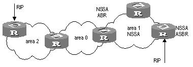
Perform the following configuration in OSPF area view.
Table 4-32 Configure NSSA of OSPF
|
Operation |
Command |
|
Configure an area to be the NSSA area |
nssa [ default-route-advertise | no-import-route | no-summary ]* |
|
Cancel the configured NSSA |
undo nssa |
|
Configure the default cost value of the route to the NSSA |
default-cost cost |
|
Restore the default cost value of the route to the NSSA area |
undo default-cost |
All the routers connected to the NSSA should use the nssa command to configure the area with the NSSA attribute.
The keyword default-route-advertise is used to generate default type-7 LSAs. When default-route-advertise is configured, a default type-7 LSA route will be generated on the ABR, even though no default route 0.0.0.0 is in the routing table. On an ASBR, however, a default type-7 LSA route can be generated only if the default route 0.0.0.0 is in the routing table.
Executing the keyword no-import-route on the ASBR will prevent the external routes that OSPF imported through the import-route command from being advertised to the NSSA. Generally, if an NSSA router is both ASBR and ABR, this keyword will be used.
The keyword default-cost is used on the ABR attached to the NSSA. Using this command, you can configure the default route cost on the ABR to NSSA.
By default, the NSSA is not configured, and the cost of the default route to the NSSA is 1.
4.2.23 Configuring OSPF and Network Management System (NMS)
I. Configuring OSPF MIB binding
After multiple OSPF processes are enabled, you can configure to which OSPF process MIB is bound.
Perform the following configuration in system view.
Table 4-33 Configure OSPF MIB binding
|
Operation |
Command |
|
Configure OSPF MIB binding |
ospf mib-binding process-id |
|
Restore the default OSPF MIB binding |
undo ospf mib-binding |
By default, MIB is bound to the first enabled OSPF process.
II. Configuring OSPF TRAP
The OSPF Trap function enables the switch to send multiple types of SNMP Trap packets in case of OSPF process exceptions. In addition, you can specify an OSPF process ID so that this functions works only on that process. If no process ID is specified, this function works on all OSPF processes.
Perform the following configuration in system view.
Table 4-34 Enable/Disable OSPF TRAP function
|
Operation |
Command |
|
Enable OSPF TRAP function |
snmp-agent trap enable ospf [ process-id ] [ ifstatechange | virifstatechange | nbrstatechange | virnbrstatechange | ifcfgerror | virifcfgerror | ifauthfail | virifauthfail | ifrxbadpkt | virifrxbadpkt | iftxretransmit | viriftxretransmit | originatelsa | maxagelsa | lsdboverflow | lsdbapproachoverflow ] |
|
Disable OSPF TRAP function |
undo snmp-agent trap enable ospf [ process-id ] [ ifstatechange | virifstatechange | nbrstatechange | virnbrstatechange | ifcfgerror | virifcfgerror | ifauthfail | virifauthfail | ifrxbadpkt | virifrxbadpkt | iftxretransmit | viriftxretransmit | originatelsa | maxagelsa | lsdboverflow | lsdbapproachoverflow ] |
By default, OSPF TRAP function is disabled. That is, the switch does not send TRAP packets when any OSPF process is abnormal.
For detailed configuration of SNMP TRAP, refer to the module “System Management" in this manual.
4.2.24 Resetting the OSPF Process
If the undo ospf command is executed on a router and then the ospf command is used to restart the OSPF process, the previous OSPF configuration will lose. With the reset ospf command, you can restart the OSPF process without losing the previous OSPF configuration.
Perform the following configuration in user view.
Table 4-35 Reset OSPF processes
|
Operation |
Command |
|
Reset one or all OSPF processes |
reset ospf [ statistics ] { all | process-id } |
Resetting the OSPF process can immediately clear invalid LSAs, and make the modified router ID effective or the DR and BDR are re-elected.
4.3 Displaying and Debugging OSPF
After the above configuration, execute the display command in any view to display the running of the OSPF configuration, and to verify the effect of the configuration. Execute the debugging command in user view to debug the OSPF module.
Table 4-36 Display and debug OSPF
|
Operation |
Command |
|
Display the brief information of the OSPF routing process |
display ospf [ process-id ] brief |
|
Display OSPF statistics |
display ospf [ process-id ] cumulative |
|
Display LSDB information of OSPF |
display ospf [ process-id ] [ area-id ] lsdb [ brief | [ asbr | ase | network | nssa | router | summary [ verbose ] ] [ ip-address ] [ originate-router ip-address | self-originate [ verbose ] ] |
|
Display OSPF peer information |
display ospf [ process-id ] peer [ brief ] |
|
Display OSPF next hop information |
display ospf [ process-id ] nexthop |
|
Display OSPF routing table |
display ospf [ process-id ] routing |
|
Display OSPF virtual links |
display ospf [ process-id ] vlink |
|
Display OSPF request list |
display ospf [ process-id ] request-queue |
|
Display OSPF retransmission list |
display ospf [ process-id ] retrans-queue |
|
Display the information of OSPF ABR and ASBR |
display ospf [ process-id ] abr-asbr |
|
View OSPF inter-area route summarization information |
display ospf [ process-id ] abr-summary |
|
Display the summary information of OSPF imported routes |
display ospf [ process-id ] asbr-summary [ ip-address mask ] |
|
Display OSPF interface information |
display ospf [ process-id ] interface |
|
Display OSPF errors |
display ospf [ process-id ] error |
|
Display the state of the global OSPF debugging switches and the state of the debugging switches for each process |
|
|
Enable OSPF packet debugging |
debugging ospf packet [ ack | dd | hello | interface interface-type interface-number | request I update ] |
|
Disable OSPF packet debugging |
undo debugging ospf packet [ ack | dd | hello | interface interface-type interface-number | request I update ] |
|
Enable OSPF event debugging |
debugging ospf event |
|
Disable OSPF event debugging |
undo debugging ospf event |
|
Enable OSPF LSA packet debugging |
debugging ospf lsa-originate |
|
Disable OSPF LSA packet debugging |
undo debugging ospf lsa-originate |
|
Enable SPF debugging of OSPF |
debugging ospf spf |
|
Disable SPF debugging of OSPF |
undo debugging ospf spf |
4.4 Typical OSPF Configuration Example
4.4.1 Configuring DR Election Based on OSPF Priority
I. Network requirements
Four S9500 series, Switch A, Switch B, Switch C and Switch D, which can perform the router functions and run OSPF, are located on the same segment, as shown in the following figure.
Configure Switch A and Switch C as DR and BDR respectively. The priority of Switch A is 100, which is the highest on the network, so it is elected as the DR. Switch C has the second highest priority, that is, 2, so it is elected as the BDR. The priority of Switch B is 0, which means that it cannot be elected as the DR. Switch D does not have a priority, which takes 1 by default.
II. Network diagram
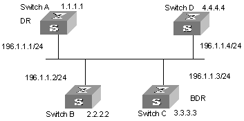
Figure 4-3 Network diagram for configuring DR election based on OSPF priority
III. Configuration procedure
# Configure Switch A
[Switch A] interface Vlan-interface 1
[Switch A-Vlan-interface1] ip address 196.1.1.1 255.255.255.0
[Switch A-Vlan-interface1] ospf dr-priority 100
[Switch A] router id 1.1.1.1
[Switch A] ospf
[Switch A-ospf-1] area 0
[Switch A-ospf-1-area-0.0.0.0] network 196.1.1.0 0.0.0.255
# Configure Switch B.
[Switch B] interface Vlan-interface 1
[Switch B-Vlan-interface1] ip address 196.1.1.2 255.255.255.0
[Switch B-Vlan-interface1] ospf dr-priority 0
[Switch B] router id 2.2.2.2
[Switch B] ospf
[Switch B-ospf-1] area 0
[Switch B-ospf-1-area-0.0.0.0] network 196.1.1.0 0.0.0.255
# Configure Switch C.
[Switch C] interface Vlan-interface 1
[Switch C-Vlan-interface1] ip address 196.1.1.3 255.255.255.0
[Switch C-Vlan-interface1] ospf dr-priority 2
[Switch C] router id 3.3.3.3
[Switch C] ospf
[Switch C-ospf-1] area 0
[Switch C-ospf-1-area-0.0.0.0] network 196.1.1.0 0.0.0.255
# Configure Switch D.
[Switch D] interface Vlan-interface 1
[Switch D-Vlan-interface1] ip address 196.1.1.4 255.255.255.0
[Switch D] router id 4.4.4.4
[Switch D] ospf
[Switch D-ospf-1] area 0
[Switch D-ospf-1-area-0.0.0.0] network 196.1.1.0 0.0.0.255
On Switch A, execute the display ospf peer command to display the OSPF peers. Note that Switch A has three peers.
The state of each peer is full, which means that adjacency is set up between Switch A and each peer. (Switch A and Switch C should set up adjacencies with all the routers on the network for them to be DR and BDR on the network respectively.) Switch A is DR, while Switch C is BDR on the network. And all the other neighbors are DR others (which means that they are neither DRs nor BDRs).
# Change the priority of Switch B to 200
[Switch B-Vlan-interface2000] ospf dr-priority 200
On Switch A, execute the display ospf peer command to show its OSPF neighbors. Note the priority of Switch B has changed to 200, but it is still not the DR.
Only when the current DR is offline, will the DR be changed. Shut down Switch A, and execute the display ospf peer command on Switch D to display its neighbors. Note that the original BDR (Switch C) becomes the DR, and Switch B is BDR now.
If all Switches on the network are removed and added back again, Switch B will be elected as the DR (with the priority of 200), and Switch A becomes the BDR (with a priority of 100). To switch off and restart all of the switches will bring about a new round of DR/BDR selection.
4.4.2 Configuring OSPF Virtual Link
I. Network requirements
In Figure 4-4, Area 2 and Area 0 are not directly connected. Area 1 is required to be taken as a transit area for connecting Area 2 and Area 0. Configure a virtual link between Switch B and Switch C in Area 1.
II. Network diagram
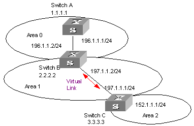
Figure 4-4 Network diagram for OSPF virtual link configuration
III. Configuration procedure
# Configure Switch A
[Switch A] interface Vlan-interface 1
[Switch A-Vlan-interface1] ip address 196.1.1.1 255.255.255.0
[Switch A] router id 1.1.1.1
[Switch A] ospf
[Switch A-ospf-1] area 0
[Switch A-ospf-1-area-0.0.0.0] network 196.1.1.0 0.0.0.255
# Configure Switch B
[Switch B] interface vlan-interface 7
[Switch B-Vlan-interface7] ip address 196.1.1.2 255.255.255.0
[Switch B] interface vlan-interface 8
[Switch B-Vlan-interface8] ip address 197.1.1.2 255.255.255.0
[Switch B] router id 2.2.2.2
[Switch B] ospf
[Switch B-ospf-1] area 0
[Switch B-ospf-1-area-0.0.0.0] network 196.1.1.0 0.0.0.255
[Switch B-ospf-1-area-0.0.0.0] quit
[Switch B-ospf-1] area 1
[Switch B-ospf-1-area-0.0.0.1] network 197.1.1.0 0.0.0.255
[Switch B-ospf-1-area-0.0.0.1] vlink-peer 3.3.3.3
# Configure Switch C
[Switch C] interface Vlan-interface 1
[Switch C-Vlan-interface1] ip address 152.1.1.1 255.255.255.0
[Switch C] interface Vlan-interface 2
[Switch C-Vlan-interface2] ip address 197.1.1.1 255.255.255.0
[Switch C] router id 3.3.3.3
[Switch C] ospf
[Switch C-ospf-1] area 1
[Switch C-ospf-1-area-0.0.0.1] network 197.1.1.0 0.0.0.255
[Switch C-ospf-1-area-0.0.0.1] vlink-peer 2.2.2.2
[Switch C-ospf-1-area-0.0.0.1] quit
[Switch C-ospf-1] area 2
[Switch C-ospf-1-area-0.0.0.2] network 152.1.1.0 0.0.0.255
4.5 Troubleshooting OSPF Faults
Symptom 1: OSPF has been configured in accordance with the earlier-mentioned steps, but OSPF on the router cannot run normally.
Solution: Check according to the following procedure.
Local troubleshooting: Check whether the protocol between two directly connected routers is in normal operation. The normal sign is the peer state machine between the two routers reaches the FULL state. (Note: On a broadcast or NBMA network, if the interfaces for two routers are in DROther state, the peer state machines for the two routers are in 2-way state, instead of FULL state. The peer state machine between DR/BDR and all the other routers is in FULL state.
l Execute the display ospf peer command to view peers.
l Execute the display ospf interface command to view OSPF information on the interface.
l Check whether the physical connections and the lower layer protocol operate normally. You can execute the ping command to test. If the local router cannot ping the peer router, it indicates that faults have occurred to the physical link and the lower layer protocol.
l If the physical link and the lower layer protocol are normal, check the OSPF parameters configured on the interface. The parameters should be the same parameters configured on the router adjacent to the interface. The same area ID should be used, and the networks and the masks should also be consistent. (The p2p or virtually linked segment can have different segments and masks.)
l Ensure that the dead timer on the same interface is at least four times the value of the Hello timer.
l If the network type is NBMA, the peer must be manually specified, using the peer ip-address command.
l If the network type is broadcast or NBMA, there must be at least one interface with a priority greater than zero.
l If an area is set as the stub area, to which the routers are connected. The area on these routers must be also set as the stub area.
l The same interface type should be adopted for the neighboring routers.
l If more than two areas are configured, at least one area should be configured as the backbone area (that is to say, the area ID is 0).
l Ensure that the backbone area is connected to all other areas.
l The virtual links do not pass through the stub area.
Global troubleshooting: If OSPF cannot discover the remote routes yet in the case that the above steps are correctly performed, proceed to check the following configurations.
l If more than two areas are configured on a router, at least one area should be configured as the backbone area.
As shown in Figure 4-5: RTA and RTD are configured to belong to only one area, whereas RTB (Area0 and Area1) and RTC (Area1 and Area 2) are configured to belong to two areas. In which, RTB also belongs to area0, which is compliant with the requirement. However, none of the areas to which RTC belongs is Area0. Therefore, a virtual link should be set up between RTC and RTB. Ensure that Area2 and Area0 (backbone area) is connected.
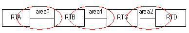
l The backbone area (Area 0) cannot be configured as the stub area and the virtual link cannot pass through the stub area. That is, if a virtual link has been set up between RTB and RTC, neither Area1 nor Area0 can be configured as a stub area. In the figure above, only Area 2 can be configured as the stub area.
l Routers in the stub area cannot receive external routes.
l The backbone area must guarantee the connectivity of all nodes.
Chapter 5 Integrated IS-IS Configuration
5.1 Introduction to Integrated IS-IS
Intermediate System-to-Intermediate System (IS-IS) intra-domain routing information exchange protocol is designed by the international organization for standardization (ISO) for connection-less network protocol (CLNP). This protocol is a dynamic routing protocol. To let this protocol support IP routing, IETF expands and modifies IS-IS in RFC1195, applying the protocol to TCP/IP and OSI. The modified IS-IS is called Integrated IS-IS or Dual IS-IS.
IS-IS is a link state protocol, which uses shortest path first (SPF) algorithm. IS-IS and the OSPF protocol are similar in many aspects. As an interior gateway protocol (IGP), IS-IS is applied inside an AS.
5.1.1 Terms of IS-IS Routing Protocol
I. Terms of IS-IS routing protocol
l Intermediate System (IS). IS equals a router of TCP/IP. It is the basic unit in IS-IS protocol used for propagating routing information and generating routes. In the following text, the IS shares the same meaning with the router.
l End System (ES). It equals the host system of TCP/IP. ES does not process the IS-IS routing protocol, and therefore it can be ignored in the IS-IS protocol.
l Routing Domain (RD). A group of ISs exchange routing information with the same routing protocol in a routing domain.
l Area. Area is the division unit in the routing domain.
l Link State DataBase (LSDB). All the link states in the network form the LSDB. In an IS, at least one LSDB is available. The IS uses the SPF algorithm and the LSDB to generate its own routes.
l Link State Protocol Data Unit (LSPDU). In the IS-IS, each IS will generate an LSP which contains all the link state information of the IS. Each IS collects all the LSPs in the local area to generate its own LSDB.
l Network Protocol Data Unit (NPDU). It is the network layer packets of OSI and equals the IP packet of TCP/IP.
l Designated IS (DIS). It is the elected router on the broadcast network.
l Network Service Access Point (NSAP) is the network layer address of OSI. It identifies an abstract network service access point and describes the very network address structure for the OSI model.
II. Link types IS-IS routing protocol is applied to
IS-IS routing protocol can run on point to point Links, such as PPP, HDLC and others. IS-IS routing protocol can also run on broadcast links, such as Ethernet, Token-Ring and others. For a Non-Broadcast Multi-Access (NBMA) network such as ATM, you need to configure sub-interfaces and configure sub-interface type as P2P or broadcast network. IS-IS routing protocol cannot run on point to MultiPoint links.
5.1.2 Two-level Structure of IS-IS Routing Protocol
I. Two-level structure of IS-IS routing protocol
Two-level structure of IS-IS routing protocol is adopted in a route area to support large scale route network. A large route area can be divided into one or multiple areas. A Level-1 router manages the intra-area routes. A Level-2 router manages the inter-area routes.
II. Level-1 and Level-2
l Level-1 router
The Level-1 router is responsible for intra-area route. The Level-1 router and the Level-1 router or Level-1-2 router in the same area are neighbors. The Level-1 router maintains a Level-1 LSDB. This LSDB contains intra-area routing information. The packets sent to other areas are forwarded to the closest Level-2 router.
l Level-2 router
The Level-2 router is responsible for inter-area route. The Level-2 router and Level-2 routers or Level-1-2 routers in other areas are neighbors. The Level-2 router maintains a Level-2 LSDB. This LSDB contains inter-area routing information. The backbone (which is made up of all Level-2 routers) of a route area is responsible for inter-area communications. The Level-2 routers in the route area must be continuous to ensure the backbone continuity.
l Level-1-2 router
A Level-1-2 router is both a Level-1 router and a Level-2 router. At least one Level-1-2 router in each area connects the area to the backbone network. A Level-1-2 router maintains two LSDBs: the Level-1 LSDB for intra- area route and Level-2 LSDB for inter-area route.
Figure 5-1 illustrates a network running IS-IS routing protocol and composed of Routing Domain 1 and Routing Domain 2. Routing Domain 1 includes two areas, Area 1 and Area 2, and Routing Domain 2 only has Area 3. In Routing Domain 1, the three ISs connected by bold lines compose the area backbone. They are all Level-2 routers. The other 4 ISs not connected by bold line are Level-1-2 routers.
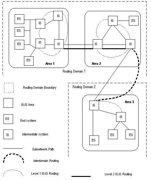
5.1.3 NSAP Structure of IS-IS Routing Protocol
I. Address structure

OSI adopts the address structure as shown in Figure 5-2. NSAP includes initial domain part (IDP) and domain specific part (DSP). The IDP is defined by ISO; it consists of authority responsible for assigning the rest of the address and address format. The DSP is allocated by the authority specified in IDP. IDP and DSP are length-variable with a total length of 20 bytes.
l Area Address
IDP includes authority and format identifier (AFI) and initial domain identifier (IDI). AFI defines the format of IDI. DSP has several bytes. The combination of IDP and HO-DSP can identify a route area and an area of the route area, so the combination is called an area address.
In general, you only need to configure an area address for a router. The area addresses of all nodes are the same in an area. To support the seamless combination, segmentation and conversion, S9500 series support up to three area addresses.
l System ID
System ID uniquely identifies terminal system or router in a route area. You can select length for it. For S9500 series, System ID length is 48 bits (6 bytes). In general, you can obtain System ID according to Router_ID.
If the IP address 168.10.1.1 of the interface LoopBack0 serves as a router_ID for the router, you can use the following method to obtain the System ID:
Turn each part of the IP address 168.10.1.1 into three digits. Add 0 to the front of the part less than three digits.
Divide the expanded address 168.010.001.001 into three parts. Each part contains four digits.
You get the System ID 1680.1000.1001.
You can specify a System ID using different methods. However, you should ensure a System ID can uniquely identify a terminal system or a router.
l SEL
NSAP selector (SEL or N-SEL) functions as the protocol identifier of an IP address. Different transmission protocols correspond to different identifiers. All the SELs of IP are 00.
Because the address structure defines clearly an area, a Level-1 router can easily identify the packets not sent to the area where it is located. The Level-1 router forwards the packets to a Level-2 router.
The Level-1 router performs routing within areas by System IDs. If it detects the destination address of a packet does not belong to the area where it is located, it forwards the packet to its closest Level-1-2 router.
The Level-2 router performs intra-area routing according to the area address (IDP + HO-DSP).
II. NET
Network Entity Title (NET) indicates the network layer information, which contains no transfer layer information (SEL=0). You can regard it as a special NSAP.
In general, you can configure a NET for a router. If you will redivide an area (combine multiple areas or divide an area into multiple areas), you can configure multiple NETs to ensure correct routes in the case of reconfiguration. Because you can configure up to three area addresses, you can only configure up to three NETs.
For example, there is a NET 47.0001.aaaa.bbbb.cccc.00, in which,
Area=47.0001, System ID=aaaa.bbbb.cccc, SEL=00.
For example, there is a NET 01.1111.2222.4444.00, in which,
Area=01, System ID=1111.2222.4444, and SEL=00.
5.1.4 IS-IS Routing Protocol Packets
IS-IS packets are directly encapsulated in the data link frames and mainly divided into 3 kinds, Hello, LSP and SNP.
I. Hello packets
Hello packets, which is also called IIH (IS-to-IS Hello PDUs), can establish and maintain neighbor relations. The Level-1 router in a broadcast LAN forwards Level-1 LAN IIH; the Level-2 router in a broadcast LAN forwards Level-2 LAN IIH; non-broadcast network forwards Point-to-Point IIH.
II. LSP
Link state packet (LSP) can switch link state information. LSP can be divided into Level-1 LSP and Level-2 LSP. Level-2 routers transmit Level-2 LSPs; Level-1 routers transmit Level-1 LSPs; Level-1-2 routers transmit both Level-2 LSPs and Level-1 LSPs.
III. SNP
Sequence Number Packet (SNP) can confirm the LSPs last received from neighbors. SNPs function as acknowledge packets, but SNPs function more validly. SNP includes complete SNP (CSNP) and partial SNP (PSNP). SNP can be further divided into Level-1 CSNP, Level-2 CSNP, Level-1 PSNP and Level-2 PSNP.
PSNP only lists one or more last received LSP sequence numbers, and confirms multiple LSPs. When detecting asynchronous LSDBs, the system asks neighbors to send new LSPs by PSNPs.
CSNP contains all LSP digest information in a LSDB, synchronizing LSDBs for neighbor routers. On a broadcast network, a DIS sends CSNPs periodically (the default sending period is 10 seconds). On the point-to-point line, a DIS sends CSNPs only when the neighbors are established for the first time.
5.2 Configuring Integrated IS-IS
Among the following configurations, the configuration of enabling integrated IS-IS is required, while other configurations are optional.
IS-IS configuration includes:
1) IS-IS basic configuration
l Enabling IS-IS and Entering the IS-IS View
l Setting Network Entity Title
l Enabling IS-IS on the Specified Interface
l Setting Priority for DIS Election
l Setting Router Type
l Setting Interface Circuit Level
2) Configuration related to IS-IS route
l Configuring IS-IS to Import Routes of Other Protocols
l Configuring IS-IS Route Filtering
l Configuring IS-IS Routing Leak
l Setting IS-IS Route Summary
l Setting to Generate Default Route
3) Default route generation
l Setting the Preference of IS-IS Protocol
l Configuring IS-IS Route Metric Type
l Setting IS-IS Link State Routing Cost
l Configuring IS-IS Timers
l Setting Parameters Related to LSP
l Setting Parameters Related to SPF
4) Configuration related to IS-IS networking
l Setting IS-IS Authentication
l Setting Overload Flag Bit
l Setting to Discard the LSPs with Checksum Errors
l Setting to Log the Peer Changes
l Setting the Mesh Group of the Interface
l Enabling/Disabling IS-IS Packet
5) Some operation commands
l Resetting All the IS-IS Data Structure
l Resetting the Specified IS-IS Peer
5.2.1 Enabling IS-IS and Entering the IS-IS View
After creating an IS-IS routing process, you should also activate this routing process at an interface that may correlate with another router. After that, the IS-IS protocol can be started and run.
Perform the following configuration in system view.
Table 5-1 Enable IS-IS and enter the IS-IS view
|
Operation |
Command |
|
Enable the IS-IS and enter the IS-IS view |
isis [ tag ] |
The tag argument identifies the IS-IS process. In the present version, just one IS-IS process is allowed.
By default, the IS-IS routing process is disabled.
5.2.2 Setting Network Entity Title
Network Entity Titles (hereafter referred to as NETs) defines the current IS-IS area address and the system ID of the router.
Perform the following configurations in IS-IS view.
|
Operation |
Command |
|
Set a NET |
network-entity network-entity-title |
|
Delete a NET |
undo network-entity network-entity-title |
The format of the network-entity-title argument is X…X.XXXXXXXXXXXX.XX, among which the first “X…X” is the area address, the twelve Xs in the middle is the System ID of the router. The last XX should be 00.
5.2.3 Enabling IS-IS on the Specified Interface
After enabling IS-IS, you need to specify on which Interfaces the IS-IS will be run.
Perform the following configuration in interface view.
Table 5-3 Enable IS-IS on the specified interface
|
Operation |
Command |
|
Enable IS-IS on the specified Interface |
isis enable [ tag ] |
|
Cancel this designation |
undo isis enable [ tag ] |
5.2.4 Setting Priority for DIS Election
In the broadcast network, the IS-IS needs to elect a DIS from all the routers.
When you need to select a DIS from the IS-IS neighbors on the broadcast network, you should select level-1 DIS and level-2 DIS respectively. The higher the priority is, the more possible it is selected. If there are two or more routers with the highest priority in the broadcast network, the one with the greatest MAC address will be selected. If all the adjacent routers' priorities are 0, the one with the greatest MAC address will be selected.
The DISs of Level-1 and Level-2 are elected separately. You can set different priorities for DIS election at different levels.
Perform the following configuration in interface view.
Table 5-4 Set priority for DIS election
|
Operation |
Command |
|
Set the priorities for DIS election on the interface |
isis dis-priority value [ level-1 | level-2 ] |
|
Restore the default priorities for DIS election on the interface |
undo isis dis-priority [ level-1 | level-2 ] |
By default, the interface priority is 64. If the level-1 or level-2 is not specified, it defaults to setting the priority of Level-1.
5.2.5 Setting Router Type
Based upon the position of the router, the levels can be divided into Level-1 (intra-domain router), Level-2 (inter-domain router) and Level-1-2 (that is, intra-domain router as well as inter-domain router).
Perform the following configuration in IS-IS view.
|
Operation |
Command |
|
Set the router type |
is-level { level-1 | level-1-2 | level-2 } |
|
Restore the default router type |
undo is-level |
By default, the router type is level-1-2.
5.2.6 Setting Interface Circuit Level
Perform the following configuration in Interface view.
Table 5-6 Set the interface circuit level
|
Operation |
Command |
|
Set the interface circuit level |
isis circuit-level [ level-1 | level-1-2 | level-2 ] |
|
Restore the default interface circuit level |
undo isis circuit-level |
& Note:
Only when the router to which the interface belongs is of Level-1-2 type, is the modification to the interface circuit level meaningful. Otherwise, the type of the router determines the level of adjacency relation.
You can set the circuit level to limit what adjacency can be established for the interface. For example, Level-1 interface can only have Level-1 adjacency. Level-2 interface can only have Level-2 adjacency. For the Level-1-2 router, you can configure some interfaces to Level-2 to prevent transmitting Level-1 Hello packets to Level-2 backbone so as to save the bandwidth. However, Level-1 and Level-2 use the same kind of Hello packet over the p2p link, and therefore such setting is unnecessary in this case.
By default, the circuit-level on the interface is level-1-2.
5.2.7 Configuring IS-IS to Import Routes of Other Protocols
For IS-IS, the routes discovered by other routing protocols are processed as the routes outside the routing domain. When importing the routes of other protocols, you can specify the default cost for them.
When IS-IS imports routes, you can also specify to import the routes to Level-1, Level-2 or Level-1-2.
Perform the following configuration in IS-IS view.
Table 5-7 Import routes of other protocols
|
Operation |
Command |
|
Import routes of other protocols |
import-route protocol [ cost value | type { external | internal } | [ level-1 | level-1-2 | level-2 ] | route-policy route-policy-name ]* |
|
Cancel importing routes from other protocols |
undo import-route protocol [ cost value | type { external | internal } | [ level-1 | level-1-2 | level-2 ] | route-policy route-policy-name ]* |
If the level is not specified in the command for importing the route, it defaults to importing the routes into level-2.
protocol specifies the routing protocol sources that can be imported, which can be direct, static, rip, bgp, and ospf, etc.
By default, IS-IS does not import routing information from any other protocols.
For more about importing routing information, refer to the "Configuring IP Routing Policy" part.
5.2.8 Configuring IS-IS Route Filtering
IS-IS protocol can filter the received and advertised routes according to the access control list specified by acl-number.
Perform the following configuration in IS-IS view.
I. Configuring to filter the routes received by IS-IS
Table 5-8 Configure to filter the received routes
|
Operation |
Command |
|
Configure to filter the received routes |
filter-policy acl-number import |
|
Cancel filtering the received routes |
undo filter-policy acl-number import |
II. Configuring to filter the advertised routes
Table 5-9 Configure to filter the advertised routes
|
Operation |
Command |
|
Configure to filter the routes advertised by IS-IS |
filter-policy acl-number export [ routing-protocol ] |
|
Configure not to filter the routes advertised by IS-IS |
undo filter-policy acl-number export [routing-protocol ] |
By default, IS-IS does not filter the route advertised by other routing protocols.
protocol specifies the routing protocol sources for advertising routes, which can be direct, static, rip, bgp, ospf, ospf-ase, and so on.
& Note:
l The filter-policy import command only filters the ISIS routes received from the neighbors, and routes that cannot pass the filter will not be added to the routing table. This command takes effect on Level-1-2 routers.
l The filter-policy export command only takes effect to the routes imported by the import-route command. If you configure the switch with only the filter-policy export command, but without configuring the import-route command to import other external routes, then the filter-policy export command does not take effect.
l If the filter-policy export command does not specify which route to be filtered, then the all the routes imported by the import-route command will be filtered.
5.2.9 Configuring IS-IS Routing Leak
By virtual of IS-IS routing leak function, a Level-1-2 router can advertise the routing information of a Level-2 area it knows to a Level-1 router.
Perform the following configuration in IS-IS view.
Table 5-10 Configure IS-IS routing leak
|
Operation |
Command |
|
Enable IS-IS routing leak |
import-route isis level-2 into level-1 [ acl acl-number ] |
|
Disable IS-IS routing leak |
undo import-route isis level-2 into level-1 [ acl acl-number ] |
By default, a Level-2 router does not advertise its routing information to a Level-1 area.
5.2.10 Setting IS-IS Route Summary
Users can set the routes with the same next hops as one route in the routing table. Perform the following configurations in IS-IS view.
Table 5-11 Set a summary route
|
Operation |
Command |
|
Set a summary route |
summary ip-address ip-mask [ level-1 | level-1-2 | level-2 ] |
|
Delete the summary route |
undo summary ip-address ip-mask [ level-1 | level-1-2 | level-2 ] |
By default, the system disables route summary.
5.2.11 Setting to Generate Default Route
In the IS-IS route domain, the Level-1 router only has the LSDB of the local area, so it can only generate the routes in the local areas. But the Level-2 router has the backbone LSDB in the IS-IS route domains and generates the backbone network routes only. If a Level-1 router in one area wants to forward the packets to other areas, it needs to first forward the packets to the closest Level-1-2 router in the local area along its default route. You do not need to configure the default Level-1 route, but need to manually configure the default Level-2 route.
Perform the following configurations in IS-IS view.
Table 5-12 Set to generate default route
|
Operation |
Command |
|
Set to generate default route |
default-route-advertise [ route-policy route-policy-name ] |
|
Set not to generate default route |
undo default-route-advertise [ route-policy route-policy-name ] |
The default route generated by this command will only be imported to the router at the same level.
5.2.12 Setting the Preference of IS-IS Protocol
In a router on which several routing protocols are concurrently operating, there is an issue of sharing and selecting the routing information among all the routing protocols. The system sets a preference for each routing protocol. When various routing protocols find the route to the same destination, the protocol with the higher preference will take effect.
Perform the following configuration in IS-IS view.
Table 5-13 Configure the preference of IS-IS protocol
|
Operation |
Command |
|
Configure the preference of IS-IS protocol |
preference value |
|
Restore the default preference of IS-IS protocol |
undo preference |
By default, the preference of IS-IS route is 15.
5.2.13 Configuring IS-IS Route Metric Type
IS-IS routing protocol has two styles of route metric:
l Narrow: The value of route metric ranges from 1 to 63.
l Wide: The value of route metric ranges from 1 to 16,777,215.
A router can choose either or both of the styles.
Perform the following configuration in IS-IS view.
Table 5-14 Configure the style for route metric values of IS-IS packets
|
Operation |
Command |
|
Configure the style for route metric values of IS-IS packets |
cost-style { narrow | wide | wide-compatible | { compatible | narrow-compatible } [ relax-spf-limit ] } |
|
Restore the default settings |
undo cost-style |
By default, IS-IS only receives and sends the packets whose route metric is in narrow style.
5.2.14 Setting IS-IS Link State Routing Cost
Users can configure the interface cost, namely, the default routing cost.
Perform the following configuration in interface view.
Table 5-15 Set IS-IS link state routing cost
|
Operation |
Command |
|
Set the routing cost of the interface |
isis cost value [ level-1 | level-2 ] |
|
Restore the default routing cost of the interface |
undo isis cost [ level-1 | level-2 ] |
If the level is not specified, the default setting is Level-1 routing cost.
The value argument is configured according to the link state of the interface.
By default, the routing cost of IS-IS on an interface is 10.
5.2.15 Configuring IS-IS Timers
I. Setting the Hello packet broadcast interval
The IS-IS periodically sends the Hello packets from the interface and the routers maintain the adjacency through the transmitting/receiving of the Hello packets The Hello packet interval can be modified.
Perform the following configuration in interface view.
Table 5-16 Set the Hello packet broadcast interval
|
Operation |
Command |
|
Set Hello packet interval, measured in seconds. |
isis timer hello seconds [ level-1 | level-2 ] |
|
Restore the default Hello packet interval on the interface |
undo isis timer hello [ level-1 | level-2 ] |
Usually, two types of Hello packets are transported over a broadcast link: Level-1 and Level-2 Hello packets. For different packets, different broadcast intervals should be set. However, there are two exceptions. One is when there is no level separation in the link, parameters of Level-1 and Level-2 need not be specified in the command (adopt the default values). So the system will set the broadcast intervals of all packets as that of the level-1 Hello packet. The other is if Hello packets are not separated according to level-1 and level-2 on the p2p links, the attribute of the packets need not be set either.
By default, Hello packets are transmitted on an interface every 10 seconds.
This command specifies to send Hello packets of the corresponding levels in the Fast Hello mode (by setting the minimum value of Hello interval to 1 second). If the number of packets is not specified in the related command, three Hello packets will be sent per second.
Perform the following configuration in interface view.
Table 5-17 Configure to send Hello packets of the corresponding levels in the Fast Hello mode
|
Operation |
Command |
|
Configure to send Hello packets of the corresponding levels in the Fast Hello mode |
isis timer hello minimal [ level-1 | level-2 ] |
|
Restore the default value of Hello interval in the Fast Hello mode. |
undo isis timer hello minimal [ level-1 | level-2 ] |
If neither level-1 nor level-2 is specified, the default setting is Level-1 and Level-2 Hello interval. Namely, the command works on both Level-1 and Level-2.
II. Setting the CSNP packet broadcast interval
The CSNP packet is transmitted by the DIS over the broadcast network to synchronize the link state database (LSDB). The CSNP packet is regularly broadcast over the broadcast network at an interval, which can be set by users.
Perform the following configuration in interface view.
Table 5-18 Set the CSNP packet broadcast interval
|
Operation |
Command |
|
Set the CSNP packet broadcast interval |
isis timer csnp seconds [ level-1 | level-2 ] |
|
Restore the default CSNP packet broadcast interval on the interface |
undo isis timer csnp [ level-1 | level-2 ] |
If the level is not specified, it defaults to setting CSNP packet broadcast interval for Level-1.
By default, the CSNP packet is transmitted via interface every 10 seconds.
III. Setting LSP packet genration interval
As specified in the IS-IS protocol, when an event takes place, the related LSP packet should be generated again. If LSP packets are generated frequently, a large amount of resources will be occupied and the route’s efficiency will be affected. The exponent digression method can improve the efficiency to a certain degree. The LSP packet generation interval can you be configured as per the actual requirement.
Perform the following configuration in IS-IS view.
Table 5-19 Set LSP packet generation interval
|
Operation |
Command |
|
Set LSP packet generation interval |
timer lsp-generation x y z [ level-1 | level-2 ] |
|
Restore the default value of LSP packet generation interval |
undo timer lsp-generation x y z [ level-1 | level-2 ] |
IV. Setting the LSP packet transmission interval
LSP carries the link state records for propagation throughout the area.
Perform the following configuration in interface view.
Table 5-20 Set the LSP packet transmission interval
|
Operation |
Command |
|
Set LSP packet interval on the interface. |
isis timer lsp time |
|
Restore the default LSP packet interval on the interface |
undo isis timer lsp |
By default, the LSP packet is transmitted via the interface every 33 milliseconds.
V. Setting LSP packet retransmission interval
Over a p2p link, if the local end does not receive the response within a period of time after it sends an LSP packet, it considers that the originally transmitted LSP packet has been lost or dropped. In order to guarantee the transmission reliability, the local router will retransmit the original LSP packet.
Perform the following configuration in interface view.
Table 5-21 Set LSP packet retransmission interval
|
Operation |
Command |
|
Set the retransmission interval of the LSP packet over p2p links |
isis timer retransmit seconds |
|
Restore the default retransmission interval of the LSP packet over p2p links |
undo isis timer retransmit |
By default, the LSP packet is transmitted every five seconds over the p2p link.
VI. Configuringnumber of invalid Hello packets for the interface
The router maintains the adjacency by sending/receiving Hello packets. When receiving no Hello packets from the peer within a time interval, the local router regards the neighbors are invalid. The time interval is called Holddown time for the IS-IS.
Setting invalid number of Hello packets can adjust the Holddown time in the IS-IS. That is to say, after continuously receiving no specified number of Hello packets, the router regards the neighbors are invalid.
Table 5-22 Set number of invalid Hello packets for the interface
|
Operation |
Command |
|
Set the number of invalid Hello packets |
isis timer holding-multiplier value [ level-1 | level-2 ] |
|
Restore the default setting |
undo isis timer holding-multiplier [ level-1 | level-2 ] |
By default, the number of the invalid Hello packets is set to 3.
If this command does not specify level-1 or level-2, the system regard the invalid Hello packets are set for both Level-1 and Level-2 routers.
5.2.16 Setting IS-IS Authentication
I. Setting interface authentication
The authentication password set on the interface is mainly used in the Hello packet so as to confirm the validity and correctness of its peers. The authentication passwords at the same level of all the interfaces of a network should be identical.
Perform the following configuration in interface view.
Table 5-23 Set interface authentication password
|
Operation |
Command |
|
Set authentication password |
isis authentication-mode { simple | md5 } password [ { level-1 | level-2 } [ ip | osi ] ] |
|
Delete authentication-mode password |
undo isis authentication-mode { simple | md5 } password [ { level-1 | level-2 } [ ip | osi ] ] |
By default, the interface is not configured with any authentication password nor performs authentication. If the level is not specified, it defaults to setting the authentication password of Level-1.
II. Setting IS-IS area or IS-IS routing domain authentication password
Users can configure the IS-IS area or the IS-IS routing domain with authentication password.
If area authentication is needed, the area authentication password will be encapsulated into the level-1 LSP, CSNP and PSNP packets, in the specified mode. If other routers in the same area also have started the area authentication, their authentication modes and passwords must be identical to those of their neighbors, so that they can work normally. Similarly, for domain authentication, the password will also be encapsulated into the level-2 LSP, CSNP and PSNP packets in the specified mode. If the routers in the backbone layer (level-2) also need domain authentication, their authentication mode and password must be identical to those of their neighbors.
Note that the passwords for authentication of the routers on the same network segment must be identical.
Perform the following configurations in IS-IS view.
Table 5-24 Set IS-IS authentication password
|
Operation |
Command |
|
Set authentication-mode password |
area-authentication-mode { simple | md5 } password [ ip | osi ] |
|
Delete authentication-mode password |
|
|
Set routing domain authentication password |
domain-authentication-mode { simple | md5 } password [ ip | osi ] |
|
Delete routing domain authentication password |
undo domain-authentication-mode { simple | md5 } [ ip | osi ] |
By default, the system does not require password or perform authentication.
III. Setting the IS-IS to use the MD5 algorithm compatible with that of the other vendors
You must configure this command when the switch needs to authenticate the devices of other vendors using MD5 algorithm in IS-IS.
Perform the following configuration in IS-IS view.
Table 5-25 Set the IS-IS to use the MD5 algorithm compatible with that of the other vendors
|
Operation |
Command |
|
Set the IS-IS to use the MD5 algorithm compatible with that of the other vendors |
md5-compatible |
|
Set the IS-IS to use the default MD5 algorithm |
undo md5-compatible |
By default, the system uses the H3C MD5 algorithm.
5.2.17 Setting the Mesh Group of the Interface
On a NBMA network, the interface of a router will flood the received LSP to other interfaces. However, this processing method applied to a network with higher connectivity and several p2p links will cause repeated LSP flooding and waste bandwidth.
To avoid such problem, you can configure several interfaces into a mesh group. The interface will flood it outside the group only.
Perform the following configuration in interface view.
Table 5-26 Set the mesh group of the interface
|
Operation |
Command |
|
Add an interface to a mesh group |
isis mesh-group { mesh-group-number | mesh-blocked } |
|
Remove the interface from a mesh group |
undo isis mesh-group |
By default, the LSP is flooded normally from the interface. When configured with the mesh-blocked keyword, it will not flood the LSP to other interfaces.
Thus the IS-IS configuration tasks on the interface are finished. The following sections discuss how to configure other parameters of IS-IS.
5.2.18 Setting Overload Flag Bit
Sometimes, the router in the IS-IS domain may encounter some problems in operation thus errors may occur in the whole routing area. In order to avoid this problem, you can set the overload flag bit for this router.
When the overload threshold is set, other routers should not send this router the packets which should be forwarded by it.
Perform the following configurations in IS-IS view.
Table 5-27 Set overload flag bit
|
Operation |
Command |
|
Set overload flag bit |
set-overload |
|
Remove the overload flag bit |
undo set-overload |
By default, no over load bit is set.
5.2.19 Setting to Discard the LSPs with Checksum Errors
After receiving an LSP packet, the local IS-IS will calculate its checksum and compares the result with the checksum in the LSP packet. This process is the checksum authentication over the received LSP. By default, even when the checksum in the packet is not consistent with the calculated result, the LSP packet is not discarded. However, when not ignoring LSP checksum error is set with the ignore-lsp-checksum-error command, the LSP packet will be discarded if the checksum error is found.
Perform the following configuration in IS-IS view.
Table 5-28 Set to discard the LSPs with checksum errors
|
Operation |
Command |
|
Set to discard the LSP with checksum error |
ignore-lsp-checksum-error |
|
Set to ignore the LSP checksum error |
undo ignore-lsp-checksum-error |
By default, the LSP checksum error is ignored.
5.2.20 Setting to Log the Peer Changes
After peer changes log is enabled, the IS-IS peer changes will be output on the configuration terminal until the log is disabled.
Perform the following configuration in IS-IS view.
Table 5-29 Set to log the peer changes
|
Operation |
Command |
|
Enable peer changes log |
log-peer-change |
|
Disable peer changes log |
undo log-peer-change |
By default, the peer changes log is disabled.
5.2.21 Setting LSP Refreshment Interval
In order to ensure that the LSPs in the whole area can maintain the synchronization, all the current LSPs will be transmitted periodically.
Perform the following configuration in IS-IS view.
Table 5-30 Set LSP refreshment interval
|
Operation |
Command |
|
Set LSP refreshment interval |
timer lsp-refresh seconds |
|
Restore the default LSP refreshment interval |
undo timer lsp-refresh |
By default, LSP is refreshed every 900 seconds (15 minutes).
5.2.22 Setting Lifetime of LSP
When a router generates the LSP of the system, it will fill in the maximum lifetime of this LSP. When other routers receive this LSP, its life time will be reduced continuously as the time goes. If updated LSP has not been received before the old one times out, this LSP will be deleted from the LSDB.
Perform the following configuration in IS-IS view.
Table 5-31 Set Lifetime of LSP
|
Operation |
Command |
|
Set lifetime of LSP |
timer lsp-max-age seconds |
|
Restore the default LSP lifetime |
undo timer lsp-max-age |
By default, LSP can live for 1200 seconds (20 minutes).
5.2.23 Setting Parameters Related to SPF
I. Setting SPF calculation interval
When IS-IS LSDB changes, the router will compute the shortest path again. However, the immediate calculation upon every change will occupy too many resources and affect the efficiency of the router. In the case that SPF computing interval is set, when LSDB changes, SPF algorithm will be run after the SPF interval times out.
Perform the following configuration in IS-IS view.
Table 5-32 Set SPF calculation interval
|
Operation |
Command |
|
Set SPF calculation interval |
timer spf second [ level-1 | level-2 ] |
|
Restore default SPF calculation interval |
undo timer spf [ level-1 | level-2 ] |
If the level is not specified, it defaults to setting the SPF calculation interval of Level-1.
By default, SPF calculation runs every 10 seconds.
II. Setting SPF calculation in slice
When there is a large number of routes in the routing table (over 150,000), SPF calculation of IS-IS may occupy the system resources for a long time. To prevent such a case, SPF calculation can be set to perform in slice.
Perform the following configuration in IS-IS view.
Table 5-33 Set SPF calculation in slice
|
Operation |
Command |
|
Set the duration of one cycle in second of SPF calculation |
spf-slice-size seconds |
|
Restore the default configuration |
undo spf-slice-size |
By default, SPF calculation is not divided into slices but runs to the end once, which can also be implemented by setting the seconds argument to 0.
After slice calculation is set, the routes that are not processed once will be calculated in one second.
Normally, the user is not recommended to modify the default configuration. When the number of routes is between 150,000 and 200,000, it is recommended to set the seconds argument to 1, that is, the duration time for SPF calculation each time is 1 second.
III. Setting SPF to release CPU actively
To prevent SPF calculation from occupying the system resources for a long time, which affects the response speed of the console, SPF can be set to automatically release the system CPU resources after processing a certain number of routes and the unprocessed routes will be calculated in one second.
Perform the following configuration in IS-IS view.
Table 5-34 Set SPF to release CPU actively
|
Operation |
Command |
|
Specify the number of routes to process before releasing CPU |
spf-delay-interval number |
|
Restore the default configuration |
undo spf-delay-interval |
By default, CPU is released once when every 5000 routes are processed by the SPF of IS-IS.
5.2.24 Enabling/Disabling IS-IS Packet Transmission
To prevent the IS-IS routing information from being obtained by some router in a certain network, the silent-interface command can be used to prohibit sending IS-IS packets via the interface connecting with the router.
Perform the following configuration in IS-IS view.
Table 5-35 Enable/Disable IS-IS packet transmission
|
Operation |
Command |
|
Disable the interface from sending IS-IS packets |
silent-interface interface-type interface-number |
|
Enable the interface to send IS-IS packets |
undo silent-interface interface-type interface-number |
By default, the interface is allowed to receive and send IS-IS packets.
The silent-interface command is only used to restrain the IS-IS packets not to be sent on the interface, but the interface routes can still be sent from other interfaces. On a switch, this command can disable/enable the specified VLAN interface to send IS-IS packets.
5.2.25 Resetting All the IS-IS Data Structure
When it is necessary to refresh some LSPs immediately, perform the following configuration in user view.
Table 5-36 Reset all the IS-IS data structures
|
Operation |
Command |
|
Reset the IS-IS data structure |
reset isis all |
By default, the IS-IS data structure is not cleared.
5.2.26 Resetting the Specified IS-IS Peer
When it is necessary to connect a specified peer again, perform the following configuration in user view.
Table 5-37 Reset the specified IS-IS peer
|
Operation |
Command |
|
Reset the specified IS-IS peer |
reset isis peer system-id |
By default, the IS-IS peer is not cleared.
5.3 Displaying and Debugging Integrated IS-IS
After completing the above configuration, execute the display command in any view to display the running state of the IS-IS configuration, and to verify the effect of the configuration. Execute the debugging command in user view to debug the IS-IS module.
Through the following configuration operations, you can view the LSDB of the IS-IS, the transmitting/receiving of various packets of the IS-IS and the SPF calculation so as to determine the IS-IS route maintenance conditions.
Table 5-38 Display and debug IS-IS
|
Operation |
Command |
|
Display IS-IS LSDB |
display isis lsdb [ [ l1 | l2 | level-1 | level-2 ] | [ [ LSPID | local ] | verbose ]* ]* |
|
Display IS-IS SPF calculation log |
display isis spf-log |
|
Display IS-IS routing information |
display isis route |
|
Display IS-IS neighbor information |
display isis peer [ verbose ] |
|
Display mesh group information |
display isis mesh-group |
|
Enable IS-IS debugging |
debugging isis { adjacency | all | authentication-error | checksum-error | circuit-information | configuration-error | datalink-receiving-packet | datalink-sending-packet | general-error | interface-information | memory-allocating | receiving-packet-content | restart-events | self-originate-update | sending-packet-content | snp-packet | spf-event | spf-summary | spf-timer | task-error | timer | update-packet } |
|
Disable IS-IS debugging |
undo debugging isis { adjacency | all | authentication-error | checksum-error | circuit-information | configuration-error | datalink-receiving-packet | datalink-sending-packet | general-error | interface-information | memory-allocating | receiving-packet-content | restart-events | self-originate-update | sending-packet-content | snp-packet | spf-event | spf-summary | spf-timer | task-error | timer | update-packet } |
5.4 Typical Integrated IS-IS Configuration Example
I. Network requirements
As is shown in Figure 5-3, Switches A, B, C and D belong to the same autonomous system. The IS-IS routing protocol is running in these four switches so as to implement route interconnection. In the network design, switches A, B, C and D belong to the same area.
II. Network diagram
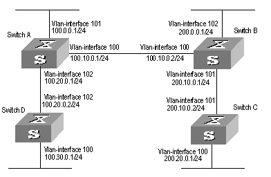
Figure 5-3 IS-IS configuration example
III. Configuration procedure
# Configure Switch A
[Switch A] isis
[Switch A-isis] network-entity 86.0001.0000.0000.0005.00
[Switch A] interface vlan-interface 100
[Switch A-Vlan-interface100] ip address 100.10.0.1 255.255.255.0
[Switch A-Vlan-interface100] isis enable
[Switch A] interface vlan-interface 101
[Switch A-Vlan-interface101] ip address 100.0.0.1 255.255.255.0
[Switch A-Vlan-interface101] isis enable
[Switch A] interface vlan-interface 102
[Switch A-Vlan-interface102] ip address 100.20.0.1 255.255.255.0
[Switch A-Vlan-interface102] isis enable
# Configure Switch B
[Switch B] isis
[Switch B-isis] network-entity 86.0001.0000.0000.0006.00
[Switch B] interface vlan-interface 101
[Switch B-Vlan-interface101] ip address 200.10.0.1 255.255.255.0
[Switch B-Vlan-interface101] isis enable
[Switch B] interface vlan-interface 102
[Switch B-Vlan-interface102] ip address 200.0.0.1 255.255.255.0
[Switch B-Vlan-interface102] isis enable
[Switch B] interface vlan-interface 100
[Switch B-Vlan-interface100] ip address 100.10.0.2 255.255.255.0
[Switch B-Vlan-interface100] isis enable
# Configure Switch C
[Switch C] isis
[Switch C-isis] network-entity 86.0001.0000.0000.0007.00
[Switch C] interface vlan-interface 101
[Switch C-Vlan-interface101] ip address 200.10.0.2 255.255.255.0
[Switch C-Vlan-interface101] isis enable
[Switch C] interface vlan-interface 100
[Switch C-Vlan-interface100] ip address 200.20.0.1 255.255.255.0
[Switch C-Vlan-interface100] isis enable
# Configure Switch D
[Switch D] isis
[Switch D-isis] network-entity 86.0001.0000.0000.0008.00
[Switch D] interface vlan-interface 102
[Switch D-Vlan-interface102] ip address 100.20.0.2 255.255.255.0
[Switch D-Vlan-interface102] isis enable
[Switch D] interface vlan-interface 100
[Switch D-Vlan-interface100] ip address 100.30.0.1 255.255.255.0
[Switch D-Vlan-interface100] isis enable
Chapter 6 BGP Configuration
6.1 BGP/MBGP Overview
6.1.1 Introduction to BGP
Border gateway protocol (BGP) is an inter-autonomous system (inter-AS) dynamic route discovery protocol. Three early versions of BGP are BGP-1 (RFC1105), BGP-2 (RFC1163) and BGP-3 (RFC1267). The current version is BGP-4 (RFC1771) that is applied to advertised structures and supports classless inter-domain routing (CIDR). Actually, BGP-4 is becoming the external routing protocol standard of the Internet, which is frequently used between ISPs.
The characteristics of BGP are as follows:
l BGP is an external gateway protocol (EGP). Different from such internal routing protocols as OSPF and RIP, it focuses on route propagation control and selection of best routes other than discovery and calculation of routes.
l It eliminates routing loop by adding AS path information to BGP routes.
l It enhances its own reliability by using TCP as the transport layer protocol.
l When routes are updated, BGP only transmits updated routes, which greatly reduces bandwidth occupation by route propagation and can be applied to propagation of a great amount of routing information on the Internet.
l BGP-4 supports CIDR, which is an important improvement to BGP-3.
l In consideration of management and security, users desire to perform control over outgoing and incoming routing information of each AS. BGP-4 provides abundant route policies to implement flexible filtering and selecting of routes.
l BGP-4 can be extended easily to support new developments of the network.
& Note:
l CIDR handles IP addresses in an entirely new way, that is, it does not distinguish networks of Class A, Class B and Class C. For example, an invalid Class C network address 192.213.0.0 (255.255.0.0) can be expressed as 192.213.0.0/16 in CIDR mode, which is a valid super network. Here /16 means that the subnet mask is composed of the first 16 bits from the left.
l The introduction of CIDR simplifies route summary. Actually, route summary is the process of aggregating several different routes, which turns advertisement processes of several routes to the advertisement of single route so as to simplify the routing table.
BGP runs on a router in any of the following modes:
l Internal BGP (IBGP)
l External BGP (EBGP)
The BGP is called IBGP when it runs in an AS and EBGP when it runs among different ASs.
6.1.2 BGP Message Types
BGP is driven by messages, which include the following types:
l Type 1, OPEN: The first message sent after the creation of a connection to create association between BGP peers.
l Type 2, UPDATE: The most important information in BGP system used to exchange routing information between peers. It is composed of up to three parts, that is, unreachable route, path attributes and network layer reachable information (NLRI).
l Type 3, NOTIFICATION: Used to notify errors.
l Type 4, KEEPALIVE: Used to check connectivity.
l Type 5, ROUTE-REFRESH: Used to advertise its own route refreshing capability.
The first four types are defined in RFC1771, while the last one is in RFC2918 (Route Refresh Capability for BGP-4).
6.1.3 BGP Routing Mechanism
On the first startup of the BGP system, the BGP router exchanges routing information with its peers by transmitting the complete BGP routing table, after that only Update messages are exchanged. In the operating of the system, keepalive messages are received and transmitted to check the connections between various neighbors.
The router transmitting BGP messages is called a BGP speaker, which receives and generates new routing information continuously and advertises the information to the other BGP speakers. When a BGP speaker receives a new route from another AS, it will advertise the route, if the route is better than the currently known route or is a new route, to all the other BGP speakers in the AS.
BGP speakers among which messages are exchanged are peers to one another. Multiple related peers compose a peer group.
I. Route advertisement policy
In the implementation of S9500 series, these policies are used by BGP when advertising routes:
l If there are multiple routes available, a BGP speaker only selects the optimum one.
l A BGP only advertises its own route to its peers.
l A BPG advertises the routes obtained from EBGP to all its BGP peers (including EBGP and IBGP peers).
l A BGP speaker does not advertise the routes obtained from IBGP to its IBGP peers.
l A BGP speaker advertises the routes obtained from IBGP to its IBGP peers (In H3C S9500 series, BGP and IGP are asynchronous.)
l Once the connection is set up, a BGP speaker will advertise all its BGP routes to its peers.
II. Route selection policy
In the implementation of S9500 series, these policies are adopted for BGP to select routes:
l First discard the routes unreachable to the next hop.
l First select the routes with the highest local preference.
l First select the routes rooted from the router itself.
l First select the routes with the least AS-paths.
l First select the routes with the lowest origin.
l First select the routes with the lowest MED value.
l First select the routes learned from EBGP.
l First select the routes advertised by the router with the lowest ID.
6.1.4 MBGP
I. MBGP overview
As described at the beginning of this chapter, BGP, as the practical exterior gateway protocol, is widely used in interconnection between autonomous systems. The traditional BGP-4 can only manage the routing information of IPv4 and has limitation in inter-AS routing when used in the application of other network layer protocols (such as IPv6 etc).
In order to support multiple network layer protocols, IETF extended BGP-4 and formed MBGP (Multiprotocol Extensions for BGP-4, multiple protocols extension of BGP-4). The present MBGP standard is RFC2858.
MBGP is backward compatible, that is, a router supporting BGP extension can be interconnected with a router that does not support it.
II. MBGP extension attributes
In the packets BGP-4 uses, three pieces of information related to IPv4 are carried in the update packet. They are Network Layer Reachability Information (NLRI), Next_Hop (The next hop address) in path attribute and Aggregator in path attribute (This attribute includes the BGP speaker address which forms the summary route).
When multiple network layer protocols are supported, it is necessary for BGP-4 to reflect the information of the specified network layer protocol to NLRI and the Next_Hop. Two new routing attributes are introduced in MBGP:
l MP_REACH_NLRI: Multiprotocol Reachable NLRI, used to advertise reachable routes and the next hop information.
l MP_UNREACH_NLRI: Multiprotocol Unreachable NLRI, used to delete unreachable routes.
These two attributes are optional non-transitive. Therefore, the BGP speaker that does not provide multiple protocols ability will ignore the information of them nor transfer them to other peers.
III. Address family
The network layer protocols are differentiated by address families in BGP. See RFC1700 (assigned numbers) for the possible values of these address families. S9500 series provide various MBGP extended applications, including extension of multicast, VPN, and so on. Different extended applications should be configured in their own address family views.
For more information about the commands executed in MBGP address family view, see “Multicast Protocol” and “MPLS Configuration” of this manual.
6.1.5 BGP Peer and Peer Group
I. Definition of peer and peer group
As described in Section 6.1.3 “BGP Routing Mechanism”, BGP speakers among which messages are exchanged are peers to one another. Multiple related peers compose a peer group, and multiple related peers compose a peer group.
II. Relationship between peer configuration and peer group configuration
In S9500 series, a BGP peer must belong to a peer group. If you want to configure a BGP peer, you need first to create a peer group and then add a peer into the group.
BGP peer group feature can simplify user configuration and improve route advertisement efficiency. When added into a peer group, a peer inherits all the configuration of the group.
If the configuration of a peer group changes, the configuration of its member peers also alters. Some attributes can be configured to a particular member peer by specifying its IP address. The attributes configured in this way is with higher priority than those by configuring for peer group. It should be noted that all member peers must use the same update policy as its group, but may use different ingress policy.
6.2 Configuring BGP
These categories are involved in BGP configuration:
1) Basic BGP configuration
l Configuring Basic Features for BGP Peer
2) BGP peer configuration
l Configuring application features of a BGP peer (group)
l Configuring Route Filtering of a Peer (group)
3) BGP route configuration
l Configuring Network Routes for BGP Distribution
l Configuring the Interaction between BGP and IGP
l Configuring BGP Route Filtering
l Configuring BGP Route Dampening
4) BGP protocol configuration
l Configuring the Local Preference
5) BGP application configuration
l Comparing the MED Routing Metrics from the Peers in Different ASs
6) BGP networking configuration
l Configuring BGP Route Reflector
l Configuring BGP AS Confederation Attribute
l Configuring BGP Load Balancing
7) Others
6.2.1 6.2.1Enabling BGP
To enable BGP, local AS number should be specified. After the enabling of BGP, local router listens to BGP connection requests sent by adjacent routers. To make the local router send BGP connection requests to adjacent routers, refer to the configuration of the peer command. When BGP is disabled, all established BGP connections will be disconnected.
Perform the following configuration in system view.
|
Operation |
Command |
|
Enable BGP and enter the BGP view |
bgp as-number |
|
Disable BGP |
undo bgp [ as-number ] |
By default, BGP is not enabled.
6.2.2 Configuring Basic Features for BGP Peer
When configuring a MBGP peer (group), you should first configure AS ID for it and then enter the corresponding address family view to activate the association.
Perform the following configurations in BGP view.
I. Creating a peer group
A BGP peer must belong to a peer group. Before configuring a BGP peer, a peer group to which the peer belongs must be created first.
|
Operation |
Command |
|
Create a peer group |
group group-name [ internal | external ] |
|
Delete the specified peer group |
undo group group-name |
There are two types of BGP peer group, IBGP and EBGP. Using the internal keyword to create an IBGP peer group. You can use the external keyword to create an EBGP peer group and sub-AS peer groups inside a confederation. group-name is locally significant.
The default type of BGP peer group is IBGP.
II. Configuring AS number of an EBGP peer group
You can specify AS number for an EBGP peer group, but IBGP needs no AS number. When a peer group is specified with an AS number, all its member peers inherit the AS number.
Table 6-3 Configure AS number of a EBGP peer group
|
Operation |
Command |
|
Configure the AS number of the EBGP peer group |
peer group-name as-number as-number |
|
Delete the AS number of the EBGP peer group |
undo peer group-name as-number as-number |
If a peer group has peers, you cannot specify an AS number for the peer group. In addition, deleting the AS number of a peer group will delete all peers in it.
III. Adding a member to a peer group
A BGP peer must belong to a peer group. If you want to configure a BGP peer, you need first to create a peer group and then add a peer into the group.
Table 6-4 Create a peer group and add a member
|
Operation |
Command |
|
Add a peer to the peer group |
peer peer-address group group-name [ as-number as-number ] |
|
Delete a peer |
undo peer peer-address |
If you want to add a peer to an IBGP peer group, this command cannot specify AS numbers.
When a peer is added to an EBGP peer group and the peer group is defined with an AS number, all its member peers inherits the configuration of the group. If the AS number of the peer group is not specified, each peer added to it should be specified with its own AS number. AS numbers of peers in a same peer group can be different.
IV. Configuring the state of a peer/peer group
BGP peer/peer group has two types of state: enabled and disabled. The BGP speakers do not exchange routing information with the disabled peer or peer group.
Table 6-5 Configure the state of a peer/peer group
|
Operation |
Command |
|
Enable a peer/peer group |
peer { group-name | peer-address } enable |
|
Disable a peer/peer group |
undo peer { group-name | peer-address } enable |
By default, only BGP peer groups of IPv4 unicast address family are enabled. Other peer types or peer group types are disabled, consequently exchanging no routing information.
When exchanging routing information between BGP speakers, the peer group must be enabled first and then the peer should be added to the enabled peer group.
V. Configuring the Graceful-restart ability of a peer or peer group
Table 6-6 Enable/disable the Graceful-restart ability of a peer or peer group
|
Operation |
Command |
|
Enable the Graceful-restart ability of a peer or peer group |
peer { peer-address | group-name } graceful-restart |
|
Disable the Graceful-restart ability of a peer or peer group |
undo peer { peer-address | group-name } graceful-restart |
VI. Configuring Graceful-restart Restart-time of a peer or peer group
Table 6-7 Configure Graceful-restart Restart-time of a peer or peer group
|
Operation |
Command |
|
Configure Graceful-restart Restart-time of a peer or peer group |
peer group-name restart-timer time-value |
|
Restore the default value of Graceful-restart Restart-time of a peer or peer group |
undo peer group-name restart-timer |
The setting of the Restart-time value is not directly related to the configuration of Graceful-restart. That is, the Restart-time can be configured before the configuration of the Graceful-restart ability. The default value of the Restart-time is 180 seconds.
VII. Configuring description of a peer (group)
Description of a peer (group) can be configured to facilitate network maintenance.
Table 6-8 Configure description of a peer (group)
|
Operation |
Command |
|
Configure description of a peer (group) |
peer { group-name | peer-address } description description-line |
|
Delete description of a peer (group) |
undo peer { group-name | peer-address } description |
By default, no BGP peer (group) description is set.
VIII. Configuring timer of a peer (group)
The peer timer command is used to configure timers of a BGP peer (group), including the keep-alive message interval and the hold timer. The preference of this command is higher than the timer command that is used to configure timers for the whole BGP peers.
Perform the following configuration in BGP view.
Table 6-9 Configure timer of a peer (group)
|
Operation |
Command |
|
Configure keep-alive message interval and hold timer of a peer (group) |
peer { group-name | peer-address } timer keep-alive keepalive-interval hold holdtime-interval} |
|
Restore the default value of keep-alive message interval and hold timer of a peer (group) |
undo peer { group-name | peer-address } timer |
By default, the Keep-alive message is sent every 60 seconds and the value of the hold timer is 180 seconds.
IX. Configuring the interval at which route update messages are sent by a peer group
Table 6-10 Configure the interval at which route update messages are sent by a peer group
|
Operation |
Command |
|
Configure the route update message interval of a peer group |
peer group-name route-update-interval seconds |
|
Restore the default route update message interval of a peer group |
undo peer group-name route-update-interval |
By default, the intervals at which route update messages are sent by an IBGP and EBGP peer group are 5 seconds and 30 seconds respectively
6.2.3 Configuring application features of a BGP peer (group)
I. Configuring to permit connections with EBGP peer groups on indirectly connected networks
Generally, EBGP peers must be connected physically. Otherwise the command below can be used to perform the configuration to make them communicate with each other normally.
Perform the following configuration in BGP view.
Table 6-11 Configure to permit connections with EBGP peer groups on indirectly connected networks
|
Operation |
Command |
|
Configure to permit connections with EBGP peer groups on indirectly connected networks |
peer group-name ebgp-max-hop [ ttl ] |
|
Configure to permit connections with EBGP peer groups on directly connected network only |
undo peer group-name ebgp-max-hop |
By default, only the connections with EBGP peer groups on directly connected networks are permitted. ttl refers to time-to-live in the range of 1 to 255 with the default value as 64.
II. Configuring an IBGP peer group to be a client of a route reflector
Perform the following configuration in BGP view.
Table 6-12 Configure an IGMP peer group to be a client of a route reflector
|
Operation |
Command |
|
Configure a peer group to be a client of a route reflector |
peer group-name reflect-client |
|
Cancel the configuration of making the peer group as the client of the BGP route reflector |
undo peer group-name reflect-client |
This configuration can be applied to IBGP peer groups only.
By default, all IBGP peers in the autonomous system must be fully connected. Moreover, neighbors do not notify the learned IBGP routes.
III. Configuring to send default route to a peer group
If you only need to notify a default route between a pair of BGP peer instead of transmitting the default route within the whole network, you can use the peer default-route-advertise command.
Perform the following configuration in BGP view.
Table 6-13 Configure to send default route to a peer group
|
Operation |
Command |
|
Configure to send default route to a peer group |
peer group-name default-route-advertise |
|
Configure not to send default route to a peer group |
undo peer group-name default-route-advertise |
By default, a BGP speaker does not send default route to any peer group.
After you use the peer default-route-advertise command, the local router will send a default route with the next hop as itself to the peer unconditionally, even if there is no default route in BGP routing table.
IV. Configuring itself as the next hop when advertising routes
In general, when sending routes to the EBGP peer, the BGP speaker will set the next hop address of the routing information as the local address. When sending routes to the IBGP peer, the BGP speaker will not modify the next hop address.
In some networking conditions, when the routes are sent to the IBGP peer, you can configure the local address of the sender as the next hop, consequently ensuring the IBGP neighbors can find the correct next hop.
Perform the following configuration in BGP view.
Table 6-14 Configure itself as the next hop when advertising routes
|
Operation |
Command |
|
Configure itself as the next hop when advertising routes |
peer group-name next-hop-local |
|
Disable the specification of itself as the next hop when advertising routes |
undo peer group-name next-hop-local |
V. Removing private AS numbers while transmitting BGP update messages
Generally, the AS numbers (public AS numbers or private AS numbers) are included in the AS paths while transmitting BGP update messages. This command is used to configure certain outbound routers to ignore the private AS numbers while transmitting update messages.
Perform the following configuration in BGP view.
Table 6-15 Remove private AS numbers while transmitting BGP update messages
|
Operation |
Command |
|
Remove private AS numbers while transmitting BGP update messages |
peer group-name public-as-only |
|
Include private AS numbers while transmitting BGP update messages |
undo peer group-name public-as-only |
By default, the private AS numbers are included during BGP update messages transmission.
The configuration can only be applied to the peer group.
VI. Configuring to send the community attributes to a peer group
Perform the following configuration in BGP view.
Table 6-16 Configure to send the community attributes to a peer group
|
Operation |
Command |
|
Configure to send the community attributes to a peer group |
peer group-name advertise-community |
|
Configure not to send the community attributes to a peer group |
undo peer group-name advertise-community |
By default, the BGP speaker does not send the community attributes to a peer group.
VII. Configuring the repeating time of local AS
BGP records the passed AS numbers in the routing information, and checks route loop depending on whether the AS number are repeated. In some special applications, it is allowed to receive the routing information with the repeated AS number.
Perform the following configuration in BGP view.
Table 6-17 Configure the repeating time of local AS
|
Operation |
Command |
|
Configure the repeating time of local AS |
peer { group-name | peer-address } allow-as-loop [ number ] |
|
Remove the repeating time of local AS |
undo peer { group-name | peer-address } allow-as-loop |
By default, the allowed repeating time of local AS is set to 1.
VIII. Specifying the source interface of a route update packet
Generally, the system specified the source interface of a route update packet. When the interface fails to work, in order to keep the TCP connection valid, the interior BGP session can be configured to specify the source interface. This command is usually used on the Loopback interface.
Table 6-18 Specify the source interface of a route update packet
|
Operation |
Command |
|
Specify the source interface of a route update packet |
peer { peer-address | group-name } connect-interface interface-type interface-name |
|
Use the best source interface |
undo peer { peer-address | group-name } connect-interface interface-type interface-name |
By default, BGP uses the interface to establish BGP links for the source interface of a route update packet.
IX. Configuring BGP MD5 authentification password
BGP uses TCP as its transport layer. For the sake of high security, you can configure MD5 authentication password when setting up a TCP connection. In other words, BGP MD5 authentication just sets password for TCP connection, but not for authenticating BGP packets. The authentication is implemented by TCP.
Perform the following configuration in BGP view.
Table 6-19 Configure BGP MD5 authentication
|
Operation |
Command |
|
Configure MD5 authentication password |
peer { group-name | peer-address } password { cipher | simple } password |
|
Cancel MD5 authentication |
undo peer { group-name | peer-address } password |
In BGP, no MD5 authentication is performed in setting up TCP connections by default.
& Note:
The multicast extension configured in BGP view is also available in MBGP, since they use the same TCP link.
6.2.4 Configuring Route Filtering of a Peer (group)
S9500 series support filtering imported and advertised routes for peers (groups) through Route-policy, AS path list, ACL and ip prefix list.
The route filtering policy of advertised routes configured for each member of a peer group must be same with that of the peer group but their route filtering policies of ingress routes may be different.
Perform the following configuration in BGP view.
I. Configuring route policy for a peer (group)
Table 6-20 Configure route policy for a peer (group)
|
Operation |
Command |
|
Configure the ingress route policy for a peer (group) |
peer { group-name | peer-address } route-policy route-policy-name import |
|
Remove the ingress route policy of a peer (group) |
undo peer { group-name | peer-address } route-policy policy-name import |
|
Configure the egress route policy for a peer group |
peer group-name route-policy route-policy-name export |
|
Remove the egress route policy of a peer group |
undo peer group-name route-policy route-policy-name export |
II. Configuring route filtering policy based on IP ACL for a peer (group)
Table 6-21 Configure route filtering policy based on IP ACL for a peer (group)
|
Operation |
Command |
|
Configure the ingress route filtering policy based on IP ACL for a peer (group) |
peer { group-name | peer-address } filter-policy acl-number import |
|
Remove the ingress route filtering policy based on IP ACL of a peer (group) |
undo peer { group-name | peer-address } filter-policy acl-number import |
|
Configure the egress route filtering policy based on IP ACL for a peer (group) |
peer group-name filter-policy acl-number export |
|
Remove the egress route filtering policy based on IP ACL for a peer (group) |
undo peer group-name filter-policy acl-number export |
III. Configuring route filtering policy based on AS path list for a peer (group)
Table 6-22 Configure route filtering policy based on AS path list for a peer (group)
|
Operation |
Command |
|
Configure the ingress route filtering policy based on AS path list for a peer (group) |
peer { group-name | peer-address } as-path-acl acl-number import |
|
Remove the ingress route filtering policy based on AS path list of a peer (group) |
undo peer { group-name | peer-address } as-path-acl acl-number import |
|
Configure the egress route filtering policy based on IP ACL for a peer group |
peer group-name as-path-acl acl-number export |
|
Remove the egress route filtering policy based on IP ACL for a peer group |
undo peer group-name as-path-acl acl-number export |
The acl-number argument indicates AS path list number, which is configured by means of the ip as-path-acl command instead of the acl command. For the detailed configuration, refer to Chapter 7 “IP Routing Policy Configuration”.
IV. Configuring route filtering policy based on address prefix list for a peer (group)
Table 6-23 Configure route filtering policy based on address prefix list for a peer (group)
|
Operation |
Command |
|
Configure the ingress route filtering policy based on address prefix list for a peer (group) |
peer { group-name | peer-address } ip-prefix prefixname import |
|
Remove the ingress route filtering policy based on address prefix list of a peer (group) |
undo peer { group-name | peer-address } ip-prefix prefixname import |
|
Configure the egress route filtering policy based on address prefix list for a peer group |
peer { group-name | peer-address ip-prefix prefixname export |
|
Remove the egress route filtering policy based on address prefix list for a peer group |
undo peer { group-name | peer-address } ip-prefix prefixname export |
By default, route filtering based on address prefix list for a peer (group) is disabled.
6.2.5 Configuring Network Routes for BGP Distribution
Perform the following configuration in BGP view.
Table 6-24 Configure network routes for BGP distribution
|
Operation |
Command |
|
Configure the local network route for BGP distribution |
network ip-address address-mask [ route-policy policy-name ] |
|
Remove the local network route for BGP distribution |
undo network ip-address address-mask [ route-policy policy-name ] |
By default, no network route is configured for BGP distribution.
6.2.6 Configuring the Interaction between BGP and IGP
I. Importing IGP routes
BGP can transmit the internal network information of local AS to other AS. To reach such objective, the network information about the internal system learned by the local router via IGP routing protocol can be transmitted.
Perform the following configuration in BGP view.
Table 6-25 Import IGP routing information
|
Operation |
Command |
|
Configure BGP to import routes of IGP protocol |
import-route protocol [ med med | route-policy policy-name ]* |
|
Configure BGP not to import routes of IGP protocol |
undo import-route protocol |
The protocol argument specifies the imported source route protocols. The specified and imported source route protocols can be direct, static, rip, isis, ospf, ospf-ase, and ospf-nssa.
By default, BGP does not import the route information of other protocols.
After you configure the import-route command in a BGP view, you cannot import the default route of the imported source route protocols to BGP by default.
II. Configuring not to syncronize with IGP
If the local BGP is not set synchronous with the IGP and the next hop of the learned BGP route is reachable, the local BGP will add this BGP route into its routing table immediately after it learns the route, rather than waiting till the IGP also learns the route.
Perform the following configuration in BGP view.
Table 6-26 Configure not to synchronize with IGP
|
Operation |
Command |
|
Cancel the synchronization of BGP and IGP |
undo synchronization |
By default, BGP does not synchronize with IGP. S9500 series switches do not support synchronization of BGP and IGP.
6.2.7 Configuring BGP Route Aggregation
The BGP supports two forms of route aggregation:
l Automatic aggregation (by means of the summary command): The aggregation of IGP subnet routes imported by the BGP. With automatic aggregation enabled, the BGP will not receive subnet routes imported from the IGP, and routes on natural network segments will be aggregated;
l Manual aggregation (by means of the aggregate command): The aggregation of the BGP local routes. In general, the preference of manual aggregation is higher than that of automatic aggregation.
Perform the following configuration in BGP view.
Table 6-27 Configure BGP route aggregation
|
Operation |
Command |
|
Enable automatic aggregation of subnet routes |
summary |
|
Disable automatic aggregation of subnet routes |
undo summary |
|
Enable local route aggregation |
aggregate address mask [ as-set | attribute-policy route-policy-name | detail-suppressed | origin-policy route-policy-name | suppress-policy route-policy-name ]* |
|
Disable local route aggregation |
undo aggregate address mask [ as-set | attribute-policy route-policy-name | detail-suppressed | origin-policy route-policy-name | suppress-policy route-policy-name ]* |
By default, the BGP does not perform local route aggregation.
6.2.8 Configuring BGP Route Filtering
I. Configuring BGP to filter the received route information
The routes received by the BGP can be filtered, and only those routes that meet the certain conditions will be received by the BGP.
Perform the following configuration in BGP view.
Table 6-28 Configure imported route filtering
|
Operation |
Command |
|
Filter received routing information advertised by specified address |
filter-policy gateway ip-prefix-name import |
|
Disable filtering of received routing information advertised by specified address |
undo filter-policy gateway ip-prefix-name import |
|
Filter received global routing information |
filter-policy { acl-number | ip-prefix ip-prefix-name } import |
|
Disable filtering of received global routings information |
undo filter-policy { acl-number | ip-prefix ip-prefix-name } import |
By default, the BGP does not filter the received routes.
II. Configuring to filter the routes advertised by other protocols
Perform the following configuration in the BGP view.
Table 6-29 Configure to filter the routes advertised by other routing protocols
|
Operation |
Command |
|
Configure to filter the routes advertised by other routing protocols |
filter-policy { acl-number | ip-prefix ip-prefix-name } export [ routing-protocol ] |
|
Cancel the filtering of the routes advertised by other routing protocols |
undo filter-policy acl-number | ip-prefix ip-prefix-name } export [ routing-protocol ] |
By default, BGP does not receive the routing information advertised by other routing protocols.
& Note:
l The filter-policy import command filters BGP route received from the neighbors. The routes that cannot pass the filter will not be added to the routing table, and will not be advertised to the neighbors.
l The filter-policy export command filters all the advertised routes, including routes imported by using the import-route command, and BGP routes learned from the neighbors.
l If the filter-policy export command does not specify which route to be filtered, then the all the routes imported by the import-route command and the advertised BGP routes will be filtered.
6.2.9 Configuring BGP Route Dampening
I. Configure BGP route dampening
Route damping is primarily used to address the route instability problem. The main possible reason for route instability is the intermittent disappearance and re-emergence of the route that formerly existed in the routing table, and this situation is called flapping. When flapping occurs, update packet will be propagated on the network repeatedly, which will occupy much bandwidth and much processing time of the router. You have to find measures to avoid it. The technology controlling unstable route is called route dampening.
The dampening divides the route into the stable route and unstable route, the latter of which shall be suppressed (not to be advertised). The history performance of the route is the basis to evaluate the future stability. When the route flapping occurs, penalty will be given, and when the penalty reaches a specific threshold, the route will be suppressed. With time going, the penalty value will decrease according to power function, and when it decreases to certain specific threshold, the route suppression will be eliminated and the route will be re-advertised.
Perform the following configuration in BGP view.
Table 6-30 Configure BGP route dampening
|
Operation |
Command |
|
Configure BGP route dampening |
dampening [ half-life-reachable half-life-unreachable reuse suppress ceiling ] [ route-policy route-policy-name ] |
|
Cancel BGP route dampening |
undo dampening |
By default, route dampening is disabled.
II. Clear route dampening information
Perform the following configuration in user view to clear route dampening information.
Table 6-31 Clear route dampening information
|
Operation |
Command |
|
Clear route dampening information |
reset bgp dampening [ network-address [ mask ] ] |
After you use the reset bgp dampening command, the command will release the suppression of suppressed routes.
6.2.10 Configuring BGP Preference
Three types of routes may be involved in BGP: routes learned from external peers (EBGP), routes learned from internal peers (IBGP) and local-originated routes. You can set preference values for the three types of route.
Perform the following configuration in BGP view.
Table 6-32 Configure BGP preference
|
Operation |
Command |
|
Configure BGP preference |
preference ebgp-value ibgp-value local-value |
|
Restore the default preference |
undo preference |
The ebgp-value, ibgp-value and local-value arguments are in the range of 1 to 256. By default, the first two is 256 and the last one is 130.
6.2.11 Configuring BGP Timer
After a BGP connection is established between two peers, they send Keepalive message to each other periodically. If a router receives no Keepalive message or any other type of packet within the set connection holdtime, the router regards the BGP connection has been interrupted and quits the BGP connection.
When a router establishes a BGP connection with a peer, the router will compare their holdtime values and uses the smaller time as the negotiated holdtime. If the negotiation result is 0, the router will not send Keepalive message and will not detect whether the holdtime expires.
Perform the following configuration in BGP view.
Table 6-33 Configure BGP timers
|
Operation |
Command |
|
Configure BGP timers |
timer keep-alive keepalive-interval hold holdtime-interval |
|
Restore the default timer value |
undo timer |
By default, the interval of sending keepalive is 60 seconds. The holdtime value is 180 seconds.
The reasonable maximum interval of sending Keepalive is one third of the holdtime value. The interval of sending Keepalive cannot be less than 1 second. As a result, if the holdtime is not 0 seconds, the minimum holdtime value is 3 seconds.
6.2.12 Configuring the Local Preference
When BGP select routes, it will select the route of the highest local preference.
Perform the following configuration in BGP view.
Table 6-34 Configure the local preference
|
Operation |
Command |
|
Configure the local preference |
default local-preference value |
|
Restore the default local preference |
undo default local-preference |
The local preference is transmitted only when the IBGP peers exchange the update packets and it will not be transmitted beyond the local AS.
By default, the local preference is 100.
6.2.13 Configuring MED for AS
Multi-Exit Discriminators (MED) attribute is the external metric for a route. AS uses the local preference to select the route to the outside, and uses the MED to determine the optimum route for entering the AS. When a router running BGP gets routes with the same destination address but different next hops through different external peers, it will select the route of the smallest MED as the optimum route, provided that all the other conditions are the same.
Perform the following configuration in BGP view.
Table 6-35 Configure an MED metric for the system
|
Operation |
Command |
|
Configure an MED metric for the system |
default med med-value |
|
Restore the default MED metric of the system |
undo default med |
By default, MED metric is 0.
The router configured above only compares the route MED metrics of different EBGP peers in the same AS. Using the compare-different-as-med command, you can compare the route MED metrics of the peers in different ASs.
6.2.14 Comparing the MED Routing Metrics from the Peers in Different ASs
It is used to select the best route. The route with smaller MED value will be selected.
Perform the following configuration in BGP view.
Table 6-36 Compare the MED routing metrics from the peers in different ASs
|
Operation |
Command |
|
Compare the MED routing metrics from peers in different ASs |
compare-different-as-med |
|
Disable comparison of the MED routing metrics from peers in different ASs |
undo compare-different-as-med |
By default, MED comparison is not allowed among the routes from the neighbors in different ASs.
It is not recommended to use this configuration unless you can make sure that the ASs adopt the same IGP and routing method.
6.2.15 Configuring BGP Route Reflector
To ensure the interconnection between IBGP peers, it is necessary to establish a fully connected network. If there are many IBGP peers, large overhead is needed to establish a fully connected network.
Route reflecting can solve the problem. Route reflector is the centralized point of other routers, and other routers are called the clients. The client is the peer of the route reflector and switching the routing information with it. The route reflector will reflect the information in order among the clients.
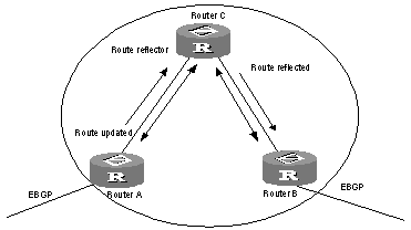
Figure 6-1 The route reflector diagram
In Figure 6-1, Router C is a route reflector with two peer clients: Router A and Router B. Router A sends to Router C the update packet from an external peer. Router C sends the update packet to Router B. After using reflecting technology, you do not need to establish a connection between Router A and Router B. You only need to connect Router C to Router A and Router B respectively.
If a BGP router is not either a reflector or client, we call the BGP router non-client. You still need connect non-clients to reflectors and non-clients.
You only need to configure route reflecting for the route reflector. When configuring the route reflector, you must specify the routers to serve as clients.
I. Configuring an IBGP peer group as route reflector client
Perform the following configuration in BGP view.
Table 6-37 Configure an IBGP peer group as route reflector client
|
Operation |
Command |
|
Configure an IBGP peer group as route reflector client |
peer group-name reflect-client |
|
Disable an IBGP peer group from being a route reflector client |
undo peer group-name reflect-client |
This command works on IBGP peer groups only.
By default, all IBGP routes in an AS must be full-connected, and neighbors do not advertise learned IBGP routes to one another.
II. Configuring the route reflection between clients
Perform the following configuration in BGP view.
Table 6-38 Configure the route reflection between clients
|
Operation |
Command |
|
Enable route reflection between clients |
reflect between-clients |
|
Disable route reflection between clients |
undo reflect between-clients |
By default, the route reflection between clients is allowed. If the clients are fully connected, for the purpose of overhead reduction, it is recommended to use the undo reflect between-clients command to disable the route reflection between clients.
III. Configuring the cluster ID
Generally, there is only one route reflector in a cluster which is identified by the router ID of the route reflector.
Perform the following configuration in BGP view.
Table 6-39 Configure the Cluster_ID of the route reflector
|
Operation |
Command |
|
Configure the Cluster_ID of the route reflector |
reflector cluster-id { cluster-id | address } |
|
Cancel the Cluster_ID of the route reflector |
undo reflector cluster-id |
The autonomous system possibly generates routing loop due to the route reflector in a cluster. After leaving a cluster, a routing update packet possibly tries to go back to the cluster. Because the routing update packet has not left an AS, the traditional AS path method cannot detect the loop inside the AS. When configuring route reflectors, you can use the following two methods to avoid loop inside the AS. One is to use the cluster ID; the other is to use Originator_ID of a route reflector.
If you configure Originator_ID improperly, the originator will discard the update packet when the update packet goes back to the originator. You do not need to configure Originator_ID. Originator_ID automatically takes effect when BGP is enabled.
6.2.16 Configuring BGP AS Confederation Attribute
Confederation provides the method to handle the booming IBGP network connections inside AS. It divides the AS into multiple sub-AS, in each of which all IBGP peers are fully connected, and are connected with other sub-AS of the confederation.
The shortcomings of confederation are that it is required that the route be re-configured upon switching from non-confederation to confederation solution, and that the logic topology be basically changed. Furthermore, the path selected via confederation may not be the best path if there is no manually-set BGP policy.
I. Configuring confederation_ID
In the eye of the BGP speakers that are not included in the confederation, multiple sub-ASs that belong to the same confederation are a whole. The external network does not need to know the status of internal sub-ASs, and the confederation ID is the AS number identifying the confederation as a whole.
Perform the following configuration in BGP view.
Table 6-40 Configure confederation_ID
|
Operation |
Command |
|
Configure confederation_ID |
confederation id as-number |
|
Cancel confederation_ID |
undo confederation id |
By default, the confederation_ID is not configured.
The configured confederation_ID and the existing AS number of a peer or peer group cannot be the same.
II. Configuring sub-AS belonging to the confederation
Configure confederation_ID first, and then configure the sub-AS belonging to the confederation. One confederation includes up to 32 sub-AS.
Perform the following configuration in BGP view.
Table 6-41 Configure sub-AS belonging to the confederation
|
Operation |
Command |
|
Configure a confederation consisting of which sub-ASs |
confederation peer-as as-number-1 [ ... as-number-n ] |
|
Cancel the specified sub-AS in the confederation |
undo confederation peer-as [ as-number-1 ] [ ...as-number-n ] |
By default, no autonomous system is configured as a member of the confederation.
The configured sub-AS number is valid only inside the confederation. In addition, the number cannot be the same as the AS number of a peer in the peer group for which you have not configured an AS number.
III. Configuring AS confederation attribute compatible with nonstandard
If it is necessary to perform the interconnection with the devices whose implementation mechanism is different from that of RFC1965, you must configure all the routers in the confederation.
Perform the following configuration in BGP view.
Table 6-42 Configure AS confederation attribute compatible with nonstandard
|
Operation |
Command |
|
Configure AS confederation attribute compatible with nonstandard router |
confederation nonstandard |
|
Cancel AS confederation attribute compatible with nonstandard router |
undo confederation nonstandard |
By default, the configured confederation is consistent with RFC1965.
6.2.17 Configuring BGP Load Balancing
As BGP is a routing protocol for route selection only, it does not provide a route calculation method. Therefore, it is not possible to determine whether to enable load balancing based on a definite metric value. However, the BGP owns a variety of route selection rules, so it supports conditional load balancing after route selection, namely, by adding load balancing into the BGP route selection rules.
With BGP load balancing enabled, during route selection, the BGP will add rule between the last two route selection rules “select routes learned from EBGP with preference” and “select routes advertised by the router with the lowest BGP ID”: if load balancing is enabled, and if there are multiple exterior routes to the same AS or AS confederation, the BGP will select multiple routes, depending on the number of routes, for load balancing. The BGP supports load balancing for routes learned from EBGP/IBGP under the following conditions:
l In case of routes learned from EBGP, the BGP performs load balancing for routes from the same AS and with the same med value only;
l In case of routes learned from IBGP, the BGP performs load balancing for routes with the same med value, local_pref, AS_PATH and origin attributes.
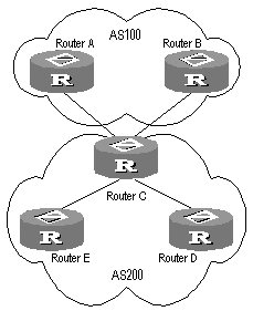
Figure 6-2 A schematic diagram of BGP load balancing
As shown in Figure 6-2, Router D and Router E are IBGP peers of Router C. When Router A and Router B simultaneously advertise two routes to the same destination to Router C, if Router C is load balancing enabled (such as balance 2), while satisfying a certain route selection rule, Router C will add both routes into the forwarding table if the two routes have the same AS_PATH attribute, so as to achieve the purpose of BGP route balancing. Router C forwards the routes to Router D and Router E only once. The AS_PATH attribute will remain unchanged, but the NEXT_HOP attribute will be changed to the address of Router C, instead of the address of the original EBGP peer. The BGP will directly transfer the other transient attributes as attributes of the optimal route.
The BGP balancing feature also applies to routing between ASs within an AS confederation.
& Note:
Load balancing is not available for BGP default routes.
Perform the following configuration in BGP view.
Table 6-43 Enable/disable BGP load balancing
|
Operation |
Command |
|
Enable BGP load balancing |
balance balance-number |
|
Disable BGP load balancing |
undo balance |
By default, the BGP does not implement load balancing.
6.2.18 Clearing BGP Connection
After the user changes BGP policy or protocol configuration, they must cut off the current connection so as to enable the new configuration.
Perform the following configuration in user view.
Table 6-44 Clear BGP connection
|
Operation |
Command |
|
Clear the connection between BGP and the specified peers |
reset bgp peer-address |
|
Clear all connections of BGP |
reset bgp all |
|
Clear the connections between the BGP and all the members of a group |
reset bgp group group-name |
6.2.19 Refreshing BGP Routes
It is required to re-compute associated route information when BGP routing policy changes.
Perform the following configuration in user view.
|
Operation |
Command |
|
Refresh general BGP routes |
refresh bgp { all | peer-address | group group-name } { import | export } | multicast | vpn-instance | vpnv4 } |
6.3 Displaying and Debugging BGP
After the above configuration, execute the display command in any view to display the running of the BGP configuration, and to verify the effect of the configuration. Execute the reset command in user view to clear the statistics of the configuration. Execute the debugging command in user view to debug the configuration. Execute the reset command in user view to reset the statistic information of BGP.
Table 6-46 Display and debug BGP
|
Operation |
Command |
|
Display the routing information in BGP routing table |
display bgp routing-table [ ip-address [ mask ] ] |
|
Display filtered AS path information in the BGP |
display ip as-path-acl acl-number |
|
Display CIDR routes |
display bgp routing-table cidr |
|
Display the routing information of the specified BGP community |
display bgp routing-table community [ aa:nn | no-export-subconfed | no-advertise | no-export ]* [ whole-match ] |
|
Display the routing information allowed by the specified BGP community list |
display bgp routing-table community-list community-list-number [ whole-match ] |
|
Display BGP dampened paths |
display bgp routing-table dampened |
|
Display the routing information the specified BGP peer advertised or received |
display bgp routing-table peer peer-address { advertised | received } [ network-address [ mask ] | statistic ] |
|
Display the total number or route entries received or advertised by all BGP peers |
display bgp routing-table { advertised | received } statistic |
|
Display the routes matching with the specified access-list |
display bgp routing-table as-path-acl acl-number |
|
Display route flapping statistics information |
display bgp routing-table flap-info [ { regular-expression as-regular-expression } | { as-path-acl acl-number } | { network-address [ mask [ longer-match ] ] } ] |
|
Display routes from different source ASs |
display bgp routing-table different-origin-as |
|
Display peers information |
display bgp peer peer-address verbose display bgp peer [ verbose ] |
|
Display the configured routing information |
display bgp network |
|
Display AS path information |
display bgp paths as-regular-expression |
|
Display peer group information |
display bgp group [ group-name ] |
|
Display the AS path information matching the specified regular expression |
display bgp routing-table regular-expression as-regular-expression |
|
Display configured route-policy information |
display route-policy [ route-policy-name ] |
|
Enable/disable debugging of all BGP packets |
[ undo ] debugging bgp all |
|
Enable/disable BGP event debugging |
[ undo ] debugging bgp event |
|
Enable/disable BGP Keepalive debugging |
[ undo ] debugging bgp keepalive [ receive | send ] [ verbose ] |
|
Enable/Disable BGP Open debugging |
[ undo ] debugging bgp open [ receive | send ] [ verbose ] |
|
Enable /Disable BGP packet debugging |
[ undo ] debugging bgp packet [ receive | send ] [ verbose ] |
|
Enable/disable BGP Route-Refresh packet debugging |
[ undo ] debugging bgp route-refresh [ receive | send ] [ verbose ] |
|
Enable/Disable information debugging of BGP normal functions. |
[ undo ] debugging bgp normal |
|
Enable/disable BGP Update packet debugging |
[ undo ] debugging bgp update [ receive | send ] [ verbose ] |
|
Reset BGP flapping statistics information |
reset bgp flap-info [ regular-expression as-regular-expression | as-path-acl acl-number | network-address [ mask ] ] |
6.4 Typical BGP Configuration Examples
6.4.1 Configuring BGP AS Confederation Attribute
I. Network requirements
Divide the following AS 100 into three sub-AS: 1001, 1002, and 1003, and configure EBGP, confederation EBGP, and IBGP.
II. Network diagram
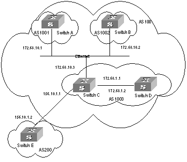
Figure 6-3 Network diagram for AS confederation configuration
III. Configuration procedure
# Configure Switch A:
[Switch A] bgp 1001
[Switch A-bgp] confederation id 100
[Switch A-bgp] confederation peer-as 1002 1003
[Switch A-bgp] group confed1002 external
[Switch A-bgp] peer confed1002 as-number 1002
[Switch A-bgp] group confed1003 external
[Switch A-bgp] peer confed1003 as-number 1003
[Switch A-bgp] peer 172.68.10.2 group confed1002
[Switch A-bgp] peer 172.68.10.3 group confed1003
# Configure Switch B:
[Switch B] bgp 1002
[Switch B-bgp] confederation id 100
[Switch B-bgp] confederation peer-as 1001 1003
[Switch B-bgp] group confed1001 external
[Switch B-bgp] peer confed1001 as-number 1001
[Switch B-bgp] group confed1003 external
[Switch B-bgp] peer confed1003 as-number 1003
[Switch B-bgp] peer 172.68.10.1 group confed1001
[Switch B-bgp] peer 172.68.10.3 group confed1003
# Configure Switch C:
[Switch C] bgp 1003
[Switch C-bgp] confederation id 100
[Switch C-bgp] confederation peer-as 1001 1002
[Switch C-bgp] group confed1001 external
[Switch C-bgp] peer confed1001 as-number 1001
[Switch C-bgp] group confed1002 external
[Switch C-bgp] peer confed1002 as-number 1002
[Switch C-bgp] peer 172.68.10.1 group confed1001
[Switch C-bgp] peer 172.68.10.2 group confed1002
[Switch C-bgp] group ebgp200 external
[Switch C-bgp] peer 156.10.1.2 group ebgp200 as-number 200
[Switch C-bgp] group ibgp1003 internal
[Switch C-bgp] peer 172.68.1.2 group ibgp1003
6.4.2 Configuring BGP Route Reflector
I. Network requirements
Switch B receives an update packet passing EBGP and transmits it to Switch C. Switch C is a reflector with two clients: Switch B and Switch D. When Switch C receives a route update from Switch B, it will transmit such information to Switch D. It is required to establish an IBGP connection between Switch B and Switch D, because Switch C reflects information to Switch D.
II. Network diagram
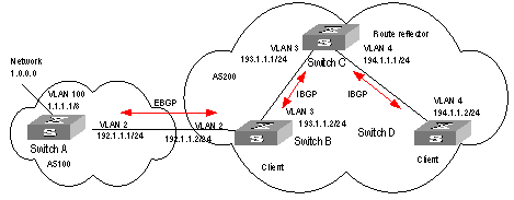
Figure 6-4 Network diagram for BGP route reflector configuration
III. Configuration procedure
1) Configure Switch A:
[Switch A] interface vlan-interface 2
[Switch A-Vlan-interface2] ip address 192.1.1.1 255.255.255.0
[Switch A-Vlan-interface2] interface Vlan-interface 100
[Switch A-Vlan-interface100] ip address 1.1.1.1 255.0.0.0
[Switch A-Vlan-interface100] quit
[Switch A] bgp 100
[Switch A-bgp] network 1.0.0.0 255.0.0.0
[Switch A-bgp] group ex external
[Switch A-bgp] peer 192.1.1.2 group ex as-number 200
2) Configure Switch B:
# Configure VLAN 2:
[Switch B] interface Vlan-interface 2
[Switch B-Vlan-interface2] ip address 192.1.1.2 255.255.255.0
# Configure VLAN 3:
[Switch B] interface Vlan-interface 3
[Switch B-Vlan-interface3] ip address 193.1.1.2 255.255.255.0
# Configure BGP peers.
[Switch B] bgp 200
[Switch B-bgp] group ex external
[Switch B-bgp] peer 192.1.1.1 group ex as-number 100
[Switch B-bgp] group in internal
[Switch B-bgp] peer 193.1.1.1 group in
3) Configure Switch C:
# Configure VLAN 3:
[Switch C] interface Vlan-interface 3
[Switch C-Vlan-interface3] ip address 193.1.1.1 255.255.255.0
# Configure VLAN 4:
[Switch C] interface vlan-Interface 4
[Switch C-Vlan-interface4] ip address 194.1.1.1 255.255.255.0
# Configure BGP peers and route reflector.
[Switch C] bgp 200
[Switch C-bgp] group rr internal
[Switch C-bgp] peer rr reflect-client
[Switch C-bgp] peer 193.1.1.2 group rr
[Switch C-bgp] peer 194.1.1.2 group rr
4) Configure Switch D:
# Configure VLAN 4:
[Switch D] interface vlan-interface 4
[Switch D-Vlan-interface4] ip address 194.1.1.2 255.255.255.0
# Configure BGP peers
[Switch D] bgp 200
group in internal
[Switch D-bgp] peer 194.1.1.1 group in
Using the display bgp routing-table command, you can view BGP routing table on Switch B. Note: Switch B has known the existence of network 1.0.0.0.
Using the display bgp routing-table command ,you can view the BGP routing table on Switch D. Note: Switch D also knows the existence of network 1.0.0.0.
6.4.3 Configuring BGP Routing
I. Network requirements
This example illustrates how the administrators manage the routing via BGP attributes. All switches are configured with BGP, and IGP in AS 200 utilizes OSPF. Switch A is in AS 100, and Switch B, Switch C and Switch D are in AS 200.Switch A, Switch B, and Switch C operate EBGP. Switch B, Switch C and Switch D operate IBGP.
II. Network diagram
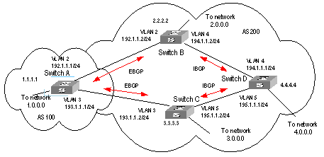
Figure 6-5 Networking diagram for BGP routing configuration
III. Configuration procedure
1) Configure Switch A:
[Switch A] interface Vlan-interface 2
[Switch A-Vlan-interface2] ip address 192.1.1.1 255.255.255.0
[Switch A] interface Vlan-interface 3
[Switch A-Vlan-interface3] ip address 193.1.1.1 255.255.255.0
# Enable BGP
[Switch A] bgp 100
# Specify the network that BGP sends to
[Switch A-bgp] network 1.0.0.0
# Configure the peers
[Switch A-bgp] group ex192 external
[Switch A-bgp] peer 192.1.1.2 group ex192 as-number 200
[Switch A-bgp] group ex193 external
[Switch A-bgp] peer 193.1.1.2 group ex193 as-number 200
[Switch A-bgp] quit
# Configure the MED attribute of Switch A
l Add ACL on Switch A, enable network 1.0.0.0.
[Switch A] acl number 2000
[Switch A-acl-basic-2000] rule permit source 1.0.0.0 0.255.255.255
[Switch A-acl-basic-2000] rule deny source any
l Define two route policies, one is called Apply_med_50 and the other is called Apply_med_100. The first MED attribute with the route policy as network 1.0.0.0 is set as 50, while the MED attribute of the second is 100.
[Switch A] route-policy apply_med_50 permit node 10
[Switch A-route-policy] if-match acl 2000
[Switch A-route-policy] apply cost 50
[Switch A-route-policy] quit
[Switch A] route-policy apply_med_100 permit node 10
[Switch A-route-policy] if-match acl 2000
[Switch A-route-policy] apply cost 100
[Switch A-route-policy] quit
l Apply route policy Apply_med_50 to egress route update of Switch C (193.1.1.2), and apply route policy Apply_med_100 on the egress route of Switch B (192.1.1.2)
[Switch A] bgp 100
[Switch A-bgp] peer ex193 route-policy apply_med_50 export
[Switch A-bgp] peer ex192 route-policy apply_med_100 export
2) Configure Switch B:
[Switch B] interface vlan-interface 2
[Switch B-Vlan-interface2] ip address 192.1.1.2 255.255.255.0
[Switch B] interface vlan-interface 4
[Switch B-Vlan-interface4] ip address 194.1.1.2 255.255.255.0
[Switch B] ospf
[Switch B-ospf-1] area 0
[Switch B-ospf-1-area-0.0.0.0] network 194.1.1.0 0.0.0.255
[Switch B-ospf-1-area-0.0.0.0] network 192.1.1.0 0.0.0.255
[Switch B] bgp 200
[Switch B-bgp] undo synchronization
[Switch B-bgp] group ex external
[Switch B-bgp] peer 192.1.1.1 group ex as-number 100
[Switch B-bgp] group in internal
[Switch B-bgp] peer 194.1.1.1 group in
[Switch B-bgp] peer 195.1.1.2 group in
3) Configure Switch C:
[Switch C] interface Vlan-interface 3
[Switch C-Vlan-interface3] ip address 193.1.1.2 255.255.255.0
[Switch C] interface vlan-interface 5
[Switch C-Vlan-interface5] ip address 195.1.1.2 255.255.255.0
[Switch C] ospf
[Switch C-ospf-1] area 0
[Switch C-ospf-1-area-0.0.0.0] network 193.1.1.0 0.0.0.255
[Switch C-ospf-1-area-0.0.0.0] network 195.1.1.0 0.0.0.255
[Switch C] bgp 200
[Switch C-bgp] group ex external
[Switch C-bgp] peer 193.1.1.1 group ex as-number 100
[Switch C-bgp] group in internal
[Switch C-bgp] peer 195.1.1.1 group in
[Switch C-bgp] peer 194.1.1.2 group in
4) Configure Switch D:
[Switch D] interface vlan-interface 4
[Switch D-Vlan-interface4] ip address 194.1.1.1 255.255.255.0
[Switch D] interface vlan-interface 5
[Switch D-Vlan-interface5] ip address 195.1.1.1 255.255.255.0
[Switch D] ospf
[Switch D-ospf-1] area 0
[Switch D-ospf-1-area-0.0.0.0] network 194.1.1.0 0.0.0.255
[Switch D-ospf-1-area-0.0.0.0] network 195.1.1.0 0.0.0.255
[Switch D-ospf-1-area-0.0.0.0] network 4.0.0.0 0.255.255.255
[Switch D] bgp 200
[Switch D-bgp] group ex external
[Switch D-bgp] peer ex as-number 200
[Switch D-bgp] peer 195.1.1.2 group ex
[Switch D-bgp] peer 194.1.1.2 group ex
To enable the configuration, all BGP neighbors will be reset using the reset bgp all command.
After above configuration, due to the fact that the MED attribute of route 1.0.0.0 discovered by Switch C is less than that of Switch B, Switch D will first select the route 1.0.0.0 from Switch C.
If the MED attribute of Switch A is not configured, the local preference on Switch C is configured as follows:
# Configure the local preference attribute of Switch C
l Add ACL 2000 on Switch C and permit network 1.0.0.0
[Switch C] acl number 2000
[Switch C-acl-basic-2000] rule permit source 1.0.0.0 0.255.255.255
[Switch C-acl-basic-2000] rule deny source any
l Define a route policy named Localpref, and set the local preference of routes matching ACL 2000 to 200, and that of routes not matching to 100.
[Switch C] route-policy localpref permit node 10
[Switch C-route-policy] if-match acl 2000
[Switch C-route-policy] apply local-preference 200
[Switch C-route-policy] route-policy localpref permit node 20
[Switch C-route-policy] apply local-preference 100
[Switch C-route-policy] quit
l Apply this route policy to ingress traffic from BGP neighbor 193.1.1.1 (Switch A)
[Switch C] bgp 200
[Switch C-bgp] peer 193.1.1.1 route-policy localpref import
By then, due to the fact that the Local preference attribute value (200) of the route 1.0.0.0 learned by Switch C is higher than that of Switch B (Switch B is not configured with local Preference attribute, 100 by default), Switch D will also first select the route 1.0.0.0 from Switch C.
6.5 Troubleshooting BGP
Symptom 1: The neighborhood cannot be established (The Established state cannot be entered).
Solution: The establishment of BGP neighborhood needs the router able to establish TCP connection through port 179 and exchange Open packets correctly. Perform the check according to the following steps:
l Check whether the configuration of the neighbor's AS number is correct.
l Check whether the neighbor's IP address is correct.
l If using the Loopback interface, check whether the connect-source loopback command has been configured. By default, the router uses the optimal local interface to establish the TCP connection, not using the loopback interface.
l If it is the EBGP neighbor not directly connected, check whether the peer ebgp-max-hop command has been configured.
l Use the ping command to check whether the TCP connection is normal. Since one router may have several interfaces able to reach the peer, the extended ping -a ip-address command should be used to specify the source IP address sending ping packet.
l If the Ping operation fails, use the display ip routing-table command to check if there is available route in the routing table to the neighbor.
l If the Ping operation succeeds, check if there is an ACL denying TCP port 179.If the ACL is configured, cancel the denying of port 179.
Symptom 2: BGP route cannot be advertised correctly after route of IGP is imported with the network command.
Solution: Route imported by the network command should be same as a route in the current routing table, which should include destination segment and mask. Route covering large network segment cannot be imported. For example, route 10.1.1.0/24 can be imported, while 10.0.0.0/8 may cause error. If Ospf is used, after a large network segment is imported to the local route by means of the network command, the router will automatically make changes according to the network segment actually used by the interface. Consequently, the network command will fail to, or incorrectly, import routes, which can cause routing errors when some network faults exist.
Chapter 7 IP Routing Policy Configuration
7.1 Introduction to IP Routing Policy
When a router advertises or receives routing information, it possibly needs to implement some policies to filter the routing information, so as to receive or advertise the routing information which can meet the specified condition only. A routing protocol, e.g. RIP, may need import the routing information discovered by other protocols to enrich its routing knowledge. While importing the routing information, it possibly only needs import the information meeting the conditions and set some special attributes to make them meet its requirement.
For implementing the routing policy, you need define a set of matching rules by specifying the characteristics of the routing information to be filtered. You can set the rules based on such attributes like destination address and source address of the information. The matching rules can be set in advance and then used in the routing policy to advertise, receive and import the route information.
7.1.1 Filter
In S9500 series, five kinds of filters, Route-policy, ACL, AS-path, Community-list, and IP-prefix, are provided to be called by the routing protocols. The following sections introduce these filters respectively.
I. ACL
The access control list (ACL) used by routing policy can be divided into the following types:
l Number-based basic ACLs
l Name-based basic ACLs
l Number-based advanced ACLs
l Name-based advanced ACLs
l Number-based L2 ACLs
l Name-based L2 ACLs
For routing information filtering, the basic ACL is generally used. When users define the ACL, they will define the range of an IP address or subnet to the destination network segment address or the next-hop address of the routing information. If an advanced ACL is used, perform the matching operation by the specified source address range.
II. IP-prefix
The function of the IP-prefix is similar to that of ACL, but it is more flexible and easy for the users to understand. When the IP-prefix is applied to the routing information filtering, its matching objects are the destination address information domain of the routing information.
An IP-prefix is identified by the IP-prefix name. Each IP-prefix can include multiple list items, and each list item can independently specify the match range of the network prefix forms and is identified with an index-number. The index-number designates the matching check sequence in the IP-prefix.
During the matching, the router checks list items identified by the sequence-number in the ascending order. Once a single list item meets the condition, it means that it has passed the IP-prefix filtering and will not enter the testing of the next list item.
III. AS-path
The AS-path list is only used in the BGP. The routing information packet of the BGP includes an autonomous system path domain (During the process of routing information exchanging of the BGP, the autonomous system paths the routing information has passed through will be recorded in this domain). Targeting at the AS path domain, the AS-path specifies the match condition.
IV. Community-list
The community-list is only used in the BGP. The routing information packet of the BGP includes a community attribute domain to identify a community. Targeting at the community attribute, the community-list specifies the match condition.
7.1.2 Routing Policy Application
Two routing policy applications are as follows:
l When advertising/receiving routing information, the router filters the information according to the route policy, and receives or advertises the routing information which can meet the specified condition only.
l When importing other routes detected by other routing protocol, the router only imports the routing information, which can meet the specified condition only, according to the route policy.
7.2 Configuring IP Routing Policy
The routing policy configuration includes:
1) Filter configuration includes:
l Configuring the AS Path List
l Configuring a Community Attribute List
& Note:
For the configuration of ACL, refer to the “QoS/ACL Operation” part of this manual.
2) Applications of routing policies include:
l Applying Route Policy on Imported Routes
l Applying Route Policy on Received or Advertised Routes
7.2.1 Configuring a Route-policy
A route-policy can comprise multiple nodes. Each node is a unit for matching operation. The nodes will be tested against by node-number.
Each node consists of a group of if-match clauses and apply clauses.
l The if-match clauses define the matching rules. The different if-match clauses for a node have the relationship of “AND”. That is, the route must satisfy all the if-match clauses for the node to match the node before passing this node.
l The apply clauses define the executed action after the routing information passes the matching test. That is, the clause sets the routing information attribute.
I. Defining a route-policy
Perform the following configuration in system view.
Table 7-1 Define a route-policy
|
Operation |
Command |
|
Enter Route policy view |
route-policy route-policy-name { permit | deny } node node-number |
|
Remove the specified route-policy |
undo route-policy route-policy-name [ permit | deny | node node-number ] |
The permit keyword specifies the matching mode for a defined node in the route-policy to be in permit mode. If a route satisfies all the if-match clauses of the node, it will pass the filtering of the node, and the apply clauses for the node will be executed without taking the test of the next node. If not, however, the route should take the test of the next node.
The deny keyword specifies the matching mode for a defined node in the route-policy to be in deny mode. In this mode, the apply clauses will not be executed. If a route satisfies all the if-match clauses of the node, it will be denied by the node and will not take the test of the next node. If not, however, the route will take the test of the next node.
The nodes have the “OR” relationship. In other words, the router will test the route against the nodes in the route-policy in sequence. Once a node is matched, the route-policy filtering will be passed.
By default, the route-policy is not defined.
Note: If multiple nodes are defined in a route-policy, at least one of them should be in permit mode. Apply the route-policy to filter routing information. If the routing information does not match any node, the routing information will be denied by the route-policy. If all the nodes in the route-policy are in deny mode, all routing information will be denied by the route-policy.
II. Defining if-match clauses for a route-policy
The if-match clauses define the matching rules. That is, the filtering conditions that the routing information should satisfy for passing the route-policy. The matching objects are some attributes of routing information.
Perform the following configuration in route policy view.
Table 7-2 Define if-match conditions
|
Operation |
Command |
|
Match the AS path domain of the BGP routing information |
if-match as-path acl-number |
|
Disable matching the AS path domain of the BGP routing information |
undo if-match as-path |
|
Match the community attribute of the BGP routing information |
if-match community { basic-community-number [ whole-match ] | adv-community-number } |
|
Disable matching the community attribute of the BGP routing information |
undo if-match community |
|
Match the destination address of the routing information |
if-match { acl acl-number | ip-prefix ip-prefix-name } |
|
Disable matching the destination address of the routing information |
undo if-match { acl | ip-prefix } |
|
Match the next-hop interface of the routing information |
|
|
Disable matching the next-hop interface of the routing information |
undo if-match interface |
|
Match the next-hop of the routing information |
if-match ip next-hop { acl acl-number | ip-prefix ip-prefix-name } |
|
Disable matching the next-hop of the routing information set by ACL |
undo if-match ip next-hop |
|
Disable matching the next-hop of the routing information set by address prefix list |
undo if-match ip next-hop ip-prefix |
|
Match the routing cost of the routing information |
if-match cost value |
|
Disable matching the routing cost of the routing information |
undo if-match cost |
|
Match the tag domain of the OSPF routing information |
if-match tag value |
|
Cancel the tag domain of the matched OSPF routing information |
undo if-match tag |
& Note:
For the details about the if-match mpls-label and if-match vpn-target commands, refer to the 08-MPLS command module in the H3C S9500 Series Routing Switches Command Manual.
By default, no matching will be performed.
Note the following:
l The if-match clauses for a node in the route-policy have the relationship of “AND” for matching. That is, the route must satisfy all the clauses to match the node before the actions specified by the apply clauses can be executed.
l If no if-match clauses are specified, all the routes will pass the filtering on the node.
III. Defining apply clauses for a route-policy
The apply clauses specify actions, which are the configuration commands executed after a route satisfies the filtering conditions specified by the if-match clauses. Thereby, some attributes of the route can be modified.
Perform the following configuration in route policy view.
Table 7-3 Define apply clauses
|
Operation |
Command |
|
Add the specified AS number before the AS-path series of the BGP routing information |
apply as-path as-number-1 [ as-number-2 [ as-number-3 ... ] ] |
|
Cancel the specified AS number added before the AS-path series of the BGP routing information |
undo apply as-path |
|
Set the community attribute in the BGP routing information |
apply community [ [ aa:nn | no-export-subconfed | no-export | no-advertise ] * [ additive ] | additive | none ] |
|
Cancel the set community attribute in the BGP routing information |
undo apply community |
|
Set the next-hop address of the routing information |
apply ip next-hop ip-address |
|
Cancel the next-hop address of the routing information |
undo apply ip next-hop |
|
Specifies to import routes to IS-IS Level-1, Level-2 or Level-1-2 |
apply isis [ level-1 | level-2 | level-1-2 ] |
|
Cancel the IS-IS level setting for route import |
undo apply isis |
|
Set the local preference of the BGP routing information |
apply local-preference local-preference |
|
Cancel the local preference of the BGP routing information |
undo apply local-preference |
|
Set the routing cost of the routing information |
apply cost value |
|
Cancel the routing cost of the routing information |
undo apply cost |
|
Set the cost type of the routing information |
apply cost-type [ internal | external ] |
|
Remove the setting of the cost type |
undo apply cost-type |
|
Set the route origin of the BGP routing information |
apply origin { igp | egp as-number | incomplete } |
|
Cancel the route origin of the BGP routing information |
undo apply origin |
|
Set the tag domain of the OSPF routing information |
apply tag value |
|
Cancel the tag domain of the OSPF routing information |
undo apply tag |
& Note:
For the details about the apply mpls-label command, refer to the 08-MPLS command module in the H3C S9500 Series Routing Switches Command Manual.
By default, perform no settings.
Note that if the routing information meets the match conditions specified in the route-policy and also notifies the MED value configured with the apply cost-type internal when notifying the IGP route to the EBGP peers, then this value will be regarded as the MED value of the IGP route. The preference configured with the apply cost-type internal command is lower than that configured with the apply cost command, but higher than that configured with the default med command.
7.2.2 Configuring ip-prefix
l An IP-prefix-list is identified by an ip-prefix-name. Each IP-prefix-list can include multiple entries each specifying an IP prefix matching range. IP prefix entries are identified by index-numbers. The order in which IP prefix entries are matched against depends on the order of their index numbers.
Perform the following configuration in system view.
|
Operation |
Command |
|
Define prefix-list |
ip ip-prefix ip-prefix-name [ index index-number ] { permit | deny } network len [ greater-equal greater-equal ] [ less-equal less-equal ] |
|
Remove prefix-list |
undo ip ip-prefix ip-prefix-name [ index index-number | permit | deny ] |
During the matching, the router checks list items identified by the index-number in the ascending order. If only one list item meets the condition, it means that it has passed the IP-prefix filtering (will not enter the testing of the next list item).
Note that if more than one ip-prefix item are defined, then the match mode of at least one list item should be the permit mode. The list items of the deny mode can be firstly defined to rapidly filter the routing information not satisfying the requirement, but if all the items are in the deny mode, no route will pass the ip-prefix filtering. You can define an item of permit 0.0.0.0/0 greater-equal 0 less-equal 32 after the multiple list items in the deny mode so as to let all the other routes pass.
7.2.3 Configuring the AS Path List
The routing information packet of the BGP includes an autonomous system path domain. The as path-list can be used to match with the autonomous system path domain of the BGP routing information so as to filter the routing information, which does not conform to the requirements.
Perform the following configuration in the system view:
Table 7-5 Define the AS path list
|
Operation |
Command |
|
Define the AS path list |
ip as-path-acl acl-number { permit | deny } as-regular-expression |
|
Delete the specified AS path list |
undo ip as-path-acl acl-number |
By default, no AS path list is defined.
7.2.4 Configuring a Community Attribute List
In BGP, community attribute is optional and transitive. Some community attributes known globally are called standard community attributes. Some community attributes are for special purpose. You can also define expanded community attribute.
A route can have one more community attributes. The speakers of multiple community attributes of a route can act according to one, several or all attributes. A router can select community attribute modification before transmitting routes to other peers.
Community lists, which identify community information, can be divided into basic-community-lists and advanced-community-lists. Basic-community-lists range from 1 to 99, while advanced-community-lists range from 100 to 199.
Perform the following configuration in system view.
Table 7-6 Configure a community attribute list
|
Operation |
Command |
|
Configure a basic community-list |
ip community-list basic-comm-list-number { permit | deny } [ aa:nn | internet | no-export-subconfed | no-advertise | no-export ]* |
|
Configure an advanced community-list |
ip community-list adv-comm-list-number { permit | deny } comm-regular-expression |
|
Cancel a community-list |
undo ip community-list { basic-comm-list-number | adv-comm-list-number } |
By default, a BGP community attribute list is not configured.
7.2.5 Applying Route Policy on Imported Routes
A routing protocol can import the routes discovered by other routing protocols to enrich its route information. The route-policy can be used for route information filtering to implement the purposeful redistribution. If the destination routing protocol importing the routes cannot directly reference the route costs of the source routing protocol, you should satisfy the requirement of the protocol by specifying a route cost for the imported route.
Perform the following configuration in routing protocol view.
Table 7-7 Configure to import the routes of other protocols
|
Operation |
Command |
|
Set to import routes of other protocols |
import-route protocol [ med med | cost cost ] [ tag value ] [ type 1 | 2 ] [ route-policy route-policy-name ] |
|
Cancel the setting for importing routes of other protocols |
undo import-route protocol |
By default, the routes discovered by other protocols will not be advertised.
& Note:
In different routing protocol views, the parameter options are different. For details, respectively refer to the import-route command in different protocols.
7.2.6 Applying Route Policy on Received or Advertised Routes
I. Configuring to filter the received routes
Perform the following configuration in routing protocol view.
Define a policy to filter the routing information not satisfying the conditions while receiving routes with the help of an ACL or address prefix-list. gateway specifies that only the update packets from a particular neighboring router will be received.
Table 7-8 Configure to filter the received routes
|
Operation |
Command |
|
Configure to filter the received routing information advertised by the specified address |
filter-policy gateway ip-prefix-name import |
|
Cancel the filtering of the received routing information advertised by the specified address |
undo filter-policy gateway ip-prefix-name import |
|
Configure to filter the received global routing information |
filter-policy { acl-number | ip-prefix ip-prefix-name } [ gateway ] import |
|
Cancel the filtering of the received global routing information |
undo filter-policy { acl-number | ip-prefix ip-prefix-name } [ gateway ] import |
II. Configuring to filter the advertised routes
You may define a route advertisement policy to filter advertised routing information. This can be done by referencing an ACL or IP prefix-list to filter routing information that does not meet the conditions, or by specifying a protocol to filter routing information of that protocol only.
Perform the following configuration in routing protocol view.
Table 7-9 Configure to filter the advertised routes
|
Operation |
Command |
|
Configure to filter the routes advertised by the protocol |
filter-policy { acl-number | ip-prefix ip-prefix-name } export [ routing-protocol ] |
|
Cancel the filtering of the routes advertised by the protocol |
undo filter-policy { acl-number | ip-prefix ip-prefix-name } export [ routing-protocol ] |
By far, the route policy supports importing the routes discovered by the following protocols into the routing table:
direct: The hop (or host) to which the local interface is directly connected.
static: Route configured statically
rip: Route discovered by RIP
ospf: Route discovered by OSPF
ospf-ase: External route discovered by OSPF
ospf-nssa: NSSA route discovered by OSPF
isis: Route discovered by IS-IS
bgp: Route acquired by BGP
By default, the filtering of the received and advertised routes will not be performed.
7.3 Displaying and Debugging the Routing Policy
After the above configuration, execute the display command in any view to display the running of the routing policy configuration, and to verify the effect of the configuration.
Table 7-10 Display and debug the route policy
|
Operation |
Command |
|
Display the routing policy |
display route-policy [ route-policy-name ] |
|
Display the path information of the AS filter in BGP |
display ip as-path-acl [ acl-number ] |
|
Display the address prefix list information |
display ip ip-prefix [ ip-prefix-name ] |
7.4 Typical IP Routing Policy Configuration Example
7.4.1 Configuring to Filter the Received Routing Information
I. Network requirements
l Switch A communicates with Switch B, running OSPF protocol. The router ID of Switch A is 1.1.1.1, and that of Switch B is 2.2.2.2.
l Import three static routes through enabling the OSPF protocol on the Switch A.
l The route filtering rules can be configured on Switch B to make the received three static routes partially visible and partially shielded. It means that routes in the network segments 20.0.0.0 and 40.0.0.0 are visible while those in the network segment 30.0.0.0 are shielded.
II. Network diagram
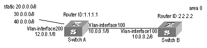
Figure 7-1 Network diagram for filtering the received routing information
III. Configuration procedure
1) Configure Switch A:
# Configure the IP address of VLAN interface.
[Switch A] interface vlan-interface 100
[Switch A-Vlan-interface100] ip address 10.0.0.1 255.0.0.0
[Switch A] interface vlan-interface 200
[Switch A-Vlan-interface200] ip address 12.0.0.1 255.0.0.0
# Configure three static routes.
[Switch A] ip route-static 20.0.0.1 255.0.0.0 12.0.0.2
[Switch A] ip route-static 30.0.0.1 255.0.0.0 12.0.0.2
[Switch A] ip route-static 40.0.0.1 255.0.0.0 12.0.0.2
# Enable the OSPF protocol and specifies the number of the area to which the interface belongs.
[Switch A] router id 1.1.1.1
[Switch A] ospf
[Switch A-ospf-1] area 0
[Switch A-ospf-1-area-0.0.0.0] network 10.0.0.0 0.255.255.255
# Import the static routes
[Switch A-ospf-1] import-route static
2) Configure Switch B:
# Configure the IP address of VLAN interface.
[Switch B] interface vlan-interface 100
[Switch B-Vlan-interface100] ip address 10.0.0.2 255.0.0.0
# Configure the access control list.
[Switch B] acl number 2000
[Switch B-acl-basic-2000] rule deny source 30.0.0.0 0.255.255.255
[Switch B-acl-basic-2000] rule permit source any
# Enable OSPF protocol and specifies the number of the area to which the interface belongs.
[Switch B] router id 2.2.2.2
[Switch B] ospf
[Switch B-ospf-1] area 0
[Switch B-ospf-1-area-0.0.0.0] network 10.0.0.0 0.255.255.255
# Configure OSPF to filter the external routes received.
[Switch B-ospf-1] filter-policy 2000 import
7.5 Troubleshooting Routing Policy
Symptom 1: Routing information filtering cannot be implemented in normal operation of the routing protocol
Solution: Check for the following faults:
l The if-match mode of at least one node of the Route-policy should be the permit mode. When a Route-policy is used for the routing information filtering, if a piece of routing information does not pass the filtering of any node, then it means that the route information does not pass the filtering of the Route-policy. When all the nodes of the Route-policy are in the deny mode, then all the routing information cannot pass the filtering of the Route-policy.
l The if-match mode of at least one list item of the ip-prefix should be the permit mode. The list items of the deny mode can be firstly defined to rapidly filter the routing information not satisfying the requirement, but if all the items are in the deny mode, any routes will not pass the ip-prefix filtering. You can define an item of permit 0.0.0.0/0 less-equal 32 after the multiple list items in the deny mode so as to let all the other routes pass the filtering (If less-equal 32 is not specified, only the default route will be matched).
Chapter 8 Route Capacity Configuration
8.1 Introduction to Route Capacity Configuration
In an actual network application, a routing table may contain a large quantity of route entries (especially OSPF routes and BGP routes). Generally, the routing information is stored in the memory of the switch and the total size of the switch memory will not change. When the size of the routing table increases to some degree, it may affect the operation of the system. To avoid the occurring of this case, you can set the specifications of routing tables and VRFs (VPN routing and forwarding instances) in the current system; and the system will inhibit any card that below any of the settings from working.
8.1.1 Configuration Tasks
|
Items |
Description |
Details |
|
Set the maximum number of route entries supported by the system |
Required |
Refer to section 8.1.2 . |
|
Set the maximum number of VRFs supported by the system |
Required |
Refer to section 8.1.3 . |
8.1.2 Setting the Maximum Number of Route Entries Supported by the System
Table 8-2 Set the maximum number of route entries supported by the system
|
Configuration steps |
Command |
Description |
|
Enter system view |
system-view |
- |
|
Set the maximum number of route entries supported by the system |
router route-limit { 128K | 256K | 512K } |
Required. By default, the system supports up to 128 K routing entries. |
8.1.3 Setting the Maximum Number of VRFs Supported by the System
Table 8-3 Set the maximum number of VRFs supported by the system
|
Configuration steps |
Command |
Description |
|
Enter system view |
system-view |
- |
|
Set the maximum number of VRFs supported by the system |
route vrf-limit { 256 | 512 | 1024 } |
Required. By default, the system supports up to 256 VRFs. |
Chapter 9 Recursive Routing Configuration
9.1 Recursive Routing Overview
Every route entry must have its next hop address. For a common route, its next hop address is within the network segment to which the router is directly connected; for a route requiring recursion, its next hop address is not within the network segment to which the router is directly connected. During route forwarding, this non-directly connected next hop address must be recursion-processed once or several times to find out a directly connected next hop address to enable L2 path searching. A recursive route can be a static route or BGP route. Recursive routing can make route entries flexible, independent of a specific interface.
9.1.1 Configuring Recursive Routing
Table 9-1 Configure recursive routing
|
Operation |
Command |
Description |
|
Enable recursive routing |
route-rely [ bgp | static ] |
By default, both routes learned by the BGP and static routes support recursive routing. |
|
Disable recursive routing |
undo route-rely [ bgp | static ] |
|
