- Table of Contents
-
- H3C S9500 Series Routing Switches Operation Manual-(V1.01)
- 00-1Cover
- 01-Getting Started Operation
- 02-Port Operation
- 03-VLAN-QinQ Operation
- 04-Network Protocol Operation
- 05-Routing Protocol Operation
- 06-Multicast Protocol Operation
- 07-QACL Operation
- 08-MPLS Operation
- 09-STP Operation
- 10-Security Operation
- 11-Reliability Operation
- 12-System Management Operation
- 13-PoE Operation
- 14-NAT-URPF-VPLS Operation
- 15-Integrated Management Operation
- 16-Appendix
- Related Documents
-
| Title | Size | Download |
|---|---|---|
| 06-Multicast Protocol Operation | 790 KB |
Table of Contents
Chapter 1 IP Multicast Overview
1.1.1 Problems with Unicast/Broadcast
1.1.3 Application of Multicast
1.2 Implementation of IP Multicast
1.3 RPF Mechanism for IP Multicast Packets
Chapter 2 IGMP Snooping Configuration
2.2 IGMP Snooping Configuration
2.2.1 Enabling/Disabling IGMP Snooping
2.2.2 Configuring Router Port Aging Time
2.2.3 Configuring Maximum Response Time
2.2.4 Configuring Aging Time of Multicast Group Member Ports
2.2.5 Configuring Unknown Multicast Packets not Broadcasted within a VLAN
2.2.6 Configuring the Filtering Rule of Multicast Groups
2.2.7 Enabling/Disabling IGMP Snooping Fast Leave
2.3 Multicast Static Routing Port Configuration
2.3.3 Configuring a Multicast Static Routing Port
2.4 Displaying and Maintaining IGMP Snooping
2.5 IGMP Snooping Configuration Example
2.6 Troubleshoot IGMP Snooping
Chapter 3 Multicast VLAN Configuration
3.2 Multicast VLAN Configuration
3.3 Multicast VLAN Configuration Example
Chapter 4 Common Multicast Configuration
4.1 Introduction to Common Multicast Configuration
4.2 Common Multicast Configuration
4.2.1 Enabling Multicast Routing
4.2.2 Configuring Multicast Routing Table Size Limit
4.2.3 Clearing MFC Forwarding Entries or Its Statistic Information
4.2.4 Clearing Route Entries from the Kernel Multicast Routing Table
4.3 Managed multicast Configuration
4.3.1 Managed multicast Overview
4.3.2 Configuring Managed Multicast
4.3.3 Managed Multicast Configuration Example
4.4 Configuring Broadcast/Multicast Suppression
4.5 Displaying and Debugging Common Multicast Configuration
5.1.2 Introduction to IGMP Proxy
5.2.2 Enabling IGMP on an Interface
5.2.3 Configuring the IGMP Version
5.2.4 Configuring the Interval to Send IGMP Query Message
5.2.5 Configuring the Interval and the Number of Querying IGMP Packets
5.2.6 Configuring the Present Time of IGMP Querier
5.2.7 Configuring Maximum Response Time for IGMP Query Message
5.2.8 Configuring the limit of IGMP groups on an interface
5.2.9 Configuring a Router to Join Specified Multicast Group
5.2.10 Deleting IGMP Groups Joined on an Interface
5.2.11 Configuring the Filtering Rule of Multicast Groups
5.2.12 Enabling/Disabling IGMP Fast Leaving
5.3.3 IGMP Configuration Example
5.4 Displaying and Debugging IGMP
Chapter 6 PIM-DM Configuration
6.1.2 PIM-DM Working Principle
6.2.3 Configuring the Time Intervals for Ports to Send Hello Packets
6.2.5 Configuring the Filtering of Multicast Source/Group
6.2.6 Configuring the Filtering of PIM Neighbor
6.2.7 Configuring the Maximum Number of PIM Neighbor on an Interface
6.2.8 Clearing PIM Routing Table Entries
6.3 Displaying and Debugging PIM-DM
6.4 PIM-DM Configuration Example
Chapter 7 PIM-SM Configuration
7.1.2 PIM-SM Working Principle
7.1.3 Preparations before Configuring PIM-SM
7.2.4 Configuring the Time Intervals for Ports to Send Hello Packets
7.2.5 Configuring Candidate-BSRs
7.2.6 Configuring Candidate-RPs
7.2.8 Configuring the PIM-SM Domain Border
7.2.9 Configuring the filtering of multicast source/group
7.2.10 Configuring the filtering of PIM neighbor
7.2.11 Configuring RP to Filter the Register Messages Sent by DR
7.2.12 Limiting the range of legal BSR
7.2.13 Limiting the range of legal C-RP
7.2.14 Clearing multicast route entries from PIM routing table
7.3 Displaying and Debugging PIM-SM
7.4 PIM-SM Configuration Example
8.2.3 Configuring Static RPF Peers
8.2.4 Configuring Originating RP
8.2.5 Configuring SA Caching State
8.2.6 Configuring the Maximum Number of SA caching
8.2.7 Requesting Source Information of MSDP Peers
8.2.8 Controlling the Source Information Created
8.2.9 Controlling the Source Information Forwarded
8.2.10 Controlling the Received Source Information
8.2.11 Configuring MSDP Mesh Group
8.2.12 Configuring the MSDP Connection Retry Period
8.2.13 Shutting MSDP Peers Down
8.2.14 Clearing MSDP Connections, Statistics and SA Caching Configuration
8.3 Displaying and Debugging MSDP
8.4 MSDP Configuration Examples
8.4.1 Configuring Static RPF Peers
8.4.3 MSDP Integrated Networking
Chapter 9 MBGP Multicast Extension Configuration
9.1 MBGP Multicast Extension Overview
9.1.2 MBGP Extension Attributes for Multicast
9.1.3 MBGP Operating Mode and Message Type
9.2 MBGP Multicast Extension Configuration
9.2.1 Enabling MBGP Multicast Extension Protocol
9.2.2 Specifying Network Routes Notified by MBGP Multicast Extension
9.2.3 Configuring the MED Value for an AS
9.2.4 Comparing MED Values from Different AS Neighbor Paths
9.2.5 Configuring Local Preference
9.2.7 Configuring MBGP Peer (Group)
9.2.8 Configuring MBGP Route Aggregation
9.2.9 Configuring an MBGP Route Reflector
9.2.10 Configure MBGP Community Attributes
9.2.11 Importing IGP Routing Information into MBGP
9.2.12 Defining AS Path List and Routing Policy
9.2.13 Configuring MBGP Route Filtering
9.2.14 Resetting BGP Connections
9.3 Displaying and Debugging MBGP Configuration
9.4 MBGP Multicast Extension Configuration Example
Chapter 1 IP Multicast Overview
An Ethernet switch functions as a router when it runs IP multicast protocol. A router that is referred to in the following represents a generalized router or a layer 3 Ethernet switch running IP multicast protocol.
1.1 IP Multicast Overview
1.1.1 Problems with Unicast/Broadcast
The constant development of the Internet and increasing interaction of versatile data, voice and video information over the network, has promoted the emergence of new services like e-commerce, network conference, online auction, video on demand (VoD), and tele-education. These services require higher information security and greater rewards.
I. Data transmission in unicast mode
In unicast mode, every user that needs the information receives a copy through the channels the system separately establishes for them. See Figure 1-1.
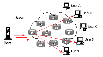
Figure 1-1 Data transmission in unicast mode
Suppose that Users B, D, and E need the information, the information source Server establishes transmission channels with every of them. Since the traffic in transmission increases with the number of users, excessive copies of the information would spread over the network if there is a large number of users in need of this information. As the bandwidth would turn short, the unicast mode is incapable of massive transmission.
II. Data transmission in broadcast mode
In broadcast mode, every user on the network receives the information regardless of their needs. See Figure 1-2 Data transmission in broadcast mode.
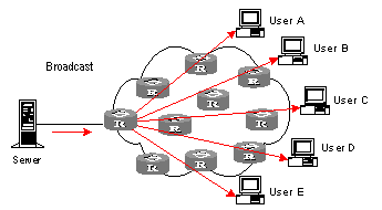
Figure 1-2 Data transmission in broadcast mode
Suppose the Users B, D, and E need the information, the information source Server broadcasts the information through the router; User A and User C can also receive the information. In that case, information security and rewards to services are not guaranteed. Moreover, bandwidth is terribly wasted when only a few part of users are in need of the information.
In short, the unicast mode is useful in networks with scattered users, and the multicast mode is suitable for networks with dense users. When the number of users is uncertain, the adoption of unicast or multicast mode results in low efficiency.
1.1.2 Advantages of Multicast
I. Multicast
IP multicast technology solves those problems. When some users in the network need specific information, it allows the multicast source to send the information only once. With the tree route established by the multicast routing protocol, the information will not be duplicated or distributed until it reaches the bifurcation point as far as possible. See Figure 1-3 Data transmission in multicast mode.
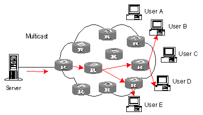
Figure 1-3 Data transmission in multicast mode
Suppose the Users B, D, and E need the information, they need to be organized into a receiver group to ensure that the information can reach them smoothly. The routers on the network duplicate and forward the information according to the distribution of these users in the group. Finally, the information is transmitted to the intended receivers B,D and E properly and correctly.
In multicast mode, the information sender is called the "multicast source", the receiver is called the "multicast group", and the routers for multicast information transmission are called "multicast routers". Members of a multicast group can scatter around the network; the multicast group therefore has no geographical limitation. It should be noted that a multicast source does not necessarily belong to a multicast group. It sends data to multicast groups but is not necessarily a receiver. Multiple sources can send packets to a multicast group simultaneously.
II. Advantages
The main advantages of multicast are:
l Enhanced efficiency: It reduces network traffic and relieves server and CPU of loads.
l Optimized performance: It eliminates traffic redundancy.
l Distributed application: It enables multipoint application.
1.1.3 Application of Multicast
IP multicast technology effectively implements point to multi-point forwarding with high speed, as saves network bandwidth a lot and can relieve network loads. It facilitates also the development of new value-added services in the Internet information service area that include online live show, Web TV, tele-education, telemedicine, network radio station and real-time audio/video conferencing. It takes a positive role in:
l Multimedia and streaming media application
l Occasional communication for training and cooperation
l Data storage and finance (stock) operation
l Point-to-multipoint data distribution
With the increasing popularity of multimedia services over IP network, multicast is gaining its marketplace. In addition, the multicast service becomes popular and prevalent gradually.
1.2 Implementation of IP Multicast
1.2.1 IP Multicast Addresses
In multicast mode, there are questions about where to send the information, how to locate the destination or know the receiver. All these questions can be narrowed down to multicast addressing. To guarantee the communication between a multicast source and a multicast group (that is, a group of receivers), the network layer multicast address (namely the IP multicast address) is required, along with the technique to correlate it with the link layer MAC multicast address. Following is the introduction to these two kinds of addresses.
I. IP Multicast Addresses
According to the definition in Internet Assigned Number Authority (IANA), IP addresses fall into four types: Class A, Class B, Class C and Class D. Unicast packets use IP addresses of Class A, Class B or Class C, depending on specific packet scales. Multicast packets use IP addresses of Class D as their destination addresses, but Class D IP addresses cannot be contained in the source IP field of IP packets.
During unicast data transmission, a packet is transmitted "hop-by-hop" from the source address to the destination address. However, in IP multicast environment, a packet has more than one destination address, or a group of addresses. All the information receivers are added to a group. Once a receiver joins the group, the data for this group address starts flowing to this receiver. All members in the group can receive the packets. This group is a multicast group.
Membership here is dynamic, and a host can join or leave the group at any time. A multicast group can be permanent or temporary. Some multicast group addresses are allocated by IANA, and the multicast group is called permanent multicast group. The IP addresses of a permanent multicast group are unchangeable, but its membership is changeable, and the number of members is arbitrary. It is quite possible for a permanent group to not a single member. Those not reserved for permanent multicast groups can be used by temporary multicast groups. Class D multicast addresses range from 224.0.0.0 to 239.255.255.255. More information is listed in Table 1-1 Ranges and meanings of Class D addresses.
Table 1-1 Ranges and meanings of Class D addresses
Reserved multicast addresses that are commonly used are described in the following table.
Table 1-2 Reserved multicast address list
|
Class D address range |
Description |
|
224.0.0.0 |
Base Address (Reserved) |
|
224.0.0.1 |
Addresses of all hosts |
|
224.0.0.2 |
Addresses of all multicast routers |
|
224.0.0.3 |
Not for allocation |
|
224.0.0.4 |
DVMRP routers |
|
224.0.0.5 |
OSPF routers |
|
224.0.0.6 |
OSPF DR |
|
224.0.0.7 |
ST routers |
|
224.0.0.8 |
ST hosts |
|
224.0.0.9 |
RIP-2 routers |
|
224.0.0.10 |
IGRP routers |
|
224.0.0.11 |
Active agents |
|
224.0.0.12 |
DHCP server/Relay agent |
|
224.0.0.13 |
All PIM routers |
|
224.0.0.14 |
RSVP encapsulation |
|
224.0.0.15 |
All CBT routers |
|
224.0.0.16 |
Specified SBM |
|
224.0.0.17 |
All SBMS |
|
224.0.0.18 |
VRRP |
|
…… |
…… |
II. Ethernet Multicast MAC Addresses
When a unicast IP packet is transmitted on the Ethernet, the destination MAC address is the MAC address of the receiver. However, for a multicast packet, the destination is no longer a specific receiver but a group with unspecific members. Therefore, the multicast MAC address should be used.
As Internet Assigned Number Authority (IANA) provisions, the high 24 bits of a multicast MAC address are 0x01005e and the low 23 bits of a MAC address are the low 23 bits of a multicast IP address. The high twenty-fifth bit is 0, a fixed value.
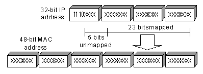
Figure 1-4 Mapping between a multicast IP address and an Ethernet MAC address
The first four bits of the multicast address are 1110, representing the multicast identifier. Among the rest 28 bits, only 23 bits are mapped to the MAC address, and the other five bits are lost. This may results in that 32 IP addresses are mapped to the same MAC address.
1.2.2 IP Multicast Protocols
IP multicast protocols mainly involves multicast group management protocols and multicast routing protocols. Their application positions are shown in Figure 1-5 Application positions of multicast-related protocols.

Figure 1-5 Application positions of multicast-related protocols
I. Multicast group management protocol
Multicast groups use Internet group management protocol (IGMP) as the management protocols. IGMP runs between the host and multicast router and defines the membership establishment and maintenance mechanism between them.
II. Multicast routing protocols
A multicast routing protocol runs between multicast routers to create and maintain multicast routes for correct and efficient forwarding of multicast packet. The multicast routing creates a loop-free data transmission path from one source to multiple receivers. The task of multicast routing protocols is to build up the distribution tree architecture. A multicast router can use multiple methods to build up a path for data transmission, that is, a distribution tree.
As in unicast routing, the multicast routing can also be intra-domain or inter-domain. Intra-domain multicast routing is rather mature and protocol independent multicast (PIM) is the most wildly used intra-domain protocol, which can work in collaboration with unicast routing protocols. The inter-domain routing first needs to solve how to transfer routing information between ASs. Since the ASs may belong to different telecom carriers, the inter-domain routing information must contain carriers’ policies, in addition to distance information. Currently, inter-domain routing protocols include multicast source discovery protocol (MSDP) and MBGP multicast extension.
1.3 RPF Mechanism for IP Multicast Packets
Chapter 2 IGMP Snooping Configuration
2.1 IGMP Snooping Overview
2.1.1 IGMP Snooping Principle
Running on the link layer, IGMP Snooping is a multicast control mechanism on the Layer 2 Ethernet switch and it is used for multicast group management and control.
When receiving the IGMP messages transmitted between the host and router, the Layer 2 Ethernet switch uses IGMP Snooping to analyze the information carried in the IGMP messages. If the switch hears IGMP host report message from an IGMP host, it will add the host to the corresponding multicast table. If the switch hears IGMP leave message from an IGMP host, it will remove the host from the corresponding multicast table. The switch continuously listens to the IGMP messages to create and maintain MAC multicast address table on Layer 2. And then it can forward the multicast packets transmitted from the upstream router according to the MAC multicast address table.
When IGMP Snooping is disabled, the packets are broadcasted on Layer 2. See the following figure:
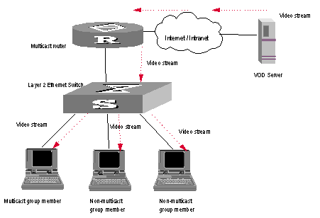
Figure 2-1 Multicast packet transmission without IGMP Snooping
When IGMP Snooping runs, the packets are multicast rather than broadcasted on Layer 2. See the following figure:
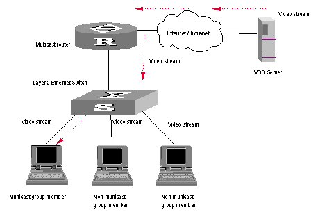
Figure 2-2 Multicast packet transmission when IGMP Snooping runs
2.1.2 Implement IGMP Snooping
I. Related concepts of IGMP Snooping
To facilitate the description, this section first introduces some related switch concepts of IGMP Snooping.
l Router Port: The port of the switch, directly connected to the multicast router.
l Multicast member port: The Ethernet switch port connected to the multicast member. The multicast member refers to a host joined a multicast group.
l MAC multicast group: The multicast group is identified with MAC multicast address and maintained by the Ethernet switch.
l Router port aging time: Time set on the router port aging timer. If the switch has not received any IGMP general query message when the timer times out, it considers the port no longer as a router port.
l Multicast group member port aging time: When a port joins an IP multicast group, the aging timer of the port will begin timing. The multicast group member port aging time is set on this aging timer. If the switch has not received any IGMP report message when the timer times out, it transmits IGMP specific query message to the port.
l Maximum response time: When the switch transmits IGMP specific query message to the multicast member port, the Ethernet switch starts a response timer, which times before the response to the query. If the switch has not received any IGMP report message before the timer times out, it will remove the port from the multicast member ports
II. Implement Layer 2 multicast with IGMP Snooping
The Ethernet switch runs IGMP Snooping to listen to the IGMP messages and map the host and its ports to the corresponding multicast group address. To implement IGMP Snooping, the Layer 2 Ethernet switch processes different IGMP messages in the way illustrated in the figure below:
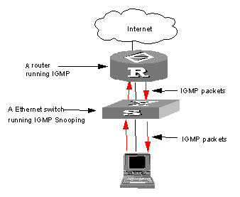
Figure 2-3 Implement IGMP Snooping
l IGMP general query message: Transmitted by the multicast router to the multicast group members to query which multicast group contains member. When an IGMP general query message arrives at a router port, the Ethernet switch will reset the aging timer of the port. When a port other than a router port receives the IGMP general query message, the Ethernet switch will start the aging timer for the port.
l IGMP specific query message: Transmitted from the multicast router to the multicast members and used for querying if a specific group contains any member. When received IGMP specific query message, the switch only transmits the specific query message to the IP multicast group which is queried.
l IGMP report message: Transmitted from the host to the multicast router and used for applying for joining a multicast group or responding to the IGMP query message. When received the IGMP report message, the switch checks if the MAC multicast group, corresponding to the IP multicast group the packet is ready to join exists.
If the corresponding MAC multicast group does not exist, the switch only notifies the router that a member is ready to join a multicast group, creates a new MAC multicast group, adds the port received the message to the group, starts the port aging timer, and then adds all the router ports in the native VLAN of the port into the MAC multicast forwarding table, and meanwhile creates an IP multicast group and adds the port received the report message to it.
If the corresponding MAC multicast group exists but does not contains the port received the report message, the switch adds the port into the multicast group and starts the port aging timer. And then the switch checks if the corresponding IP multicast group exists.
If it does not exist, the switch creates a new IP multicast group and adds the port received the report message to it. If it exists, the switch adds the port to it.
If the MAC multicast group corresponding to the message exists and contains the port received the message, the switch will only reset the aging timer of the port.
l IGMP leave message: Transmitted from the multicast group member to the multicast router to notify that a host left the multicast group. When received a leave message of an IP multicast group, the Ethernet switch transmits the specific query message concerning that group to the port received the message, in order to check if the host still has some other member of this group and meanwhile starts a maximum response timer. If the switch has not receive any report message from the multicast group after the timer expires, the port will be removed from the corresponding MAC multicast group. If the MAC multicast group does not have any member, the switch will notify the multicast router to remove the branch from the multicast tree.
2.2 IGMP Snooping Configuration
The main IGMP Snooping configuration includes:
l Enabling/Disabling IGMP Snooping
l Configuring Router Port Aging Time
l Configuring Maximum Response Time
l Configuring Aging Time of Multicast Group Member Ports
l Configuring Unknown Multicast Packets not Broadcasted within a VLAN
l Configuring the Filtering Rule of Multicast Groups
l Enabling/Disabling IGMP Snooping Fast Leave
2.2.1 Enabling/Disabling IGMP Snooping
You can use the following commands to enable/disable IGMP Snooping to control whether MAC multicast forwarding table is created and maintained on Layer 2.
Perform the following configuration in system view and VLAN view.
Table 2-1 Enabling/Disabling IGMP Snooping
|
Operation |
Command |
|
Enable/disable IGMP Snooping |
igmp-snooping { enable | disable } |
By default, IGMP Snooping is disabled.
![]() Caution:
Caution:
l First enable IGMP Snooping globally in system view, and then enable IGMP Snooping in VLAN view. Otherwise, IGMP Snooping will not take effect.
l Although layer 2 and layer 3 multicast protocols can be configured in pair, they cannot run on the same VLAN or its corresponding VLAN interface at the same time. For example, if PIM or IGMP is enabled on a VLAN, then IGMP Snooping cannot operate on this VLAN.
l If the VLAN VPN is enabled on a port, the IGMP Snooping feature cannot be enabled on the VLAN for the port or the IGMP feature cannot be enabled on the corresponding VLAN interface.
l If IGMP Snooping feature is enabled on a VLAN, or IGMP is enabled on the VLAN interface, you cannot add the member port on which VLAN VPN is enabled into the VLAN.
l Isolate-user-VLAN supports the IGMP-Snooping function. After IGMP-Snooping is enabled under isolate-user-VLAN, all secondary VLANs are IGMP-Snooping enabled. It makes no sense to enable IGMP-Snooping for a secondary VLAN.
l In a secondary VLAN, IGMP packets will be directly converted and processed in isolate-user-VLAN, namely all the multicast services are implemented within isolate-user-VLAN.
l Ports in secondary VLANs cannot be used as source addresses of multicast.
2.2.2 Configuring Router Port Aging Time
This task is to manually configure the router port aging time. If the switch has not received any general query message from the router before the router port is aged, it will remove the port from all MAC multicast groups.
Perform the following configuration in system view.
Table 2-2 Configuring router port aging time
|
Operation |
Command |
|
Configure router port aging time |
igmp-snooping router-aging-time seconds |
|
Restore the default aging time of the router port |
undo igmp-snooping router-aging-time |
By default, the router port aging time is 105s.
2.2.3 Configuring Maximum Response Time
This task is to manually configure the maximum response time. If the Ethernet switch receives no report message from a port within the maximum response time, it will remove the port from the multicast group.
Perform the following configuration in system view.
Table 2-3 Configuring the maximum response time
|
Operation |
Command |
|
Configure the maximum response time |
igmp-snooping max-response-time seconds |
|
Restore the default setting |
undo IGMP-snooping max-response-time |
By default, the maximum response time is 1 seconds.
2.2.4 Configuring Aging Time of Multicast Group Member Ports
This task is to manually set the aging time of the multicast group member port. If the Ethernet switch receives no multicast group report message during the member port aging time, it will transmit the specific query message to that port and starts a maximum response timer.
Perform the following configuration in system view.
Table 2-4 Configuring aging time of the multicast member ports
|
Operation |
Command |
|
Configure aging time of the multicast member |
igmp-snooping host-aging-time seconds |
|
Restore the default setting |
undo igmp-snooping host-aging-time |
By default, the aging time of the multicast member is 260 seconds.
2.2.5 Configuring Unknown Multicast Packets not Broadcasted within a VLAN
This configuration task is to enable/disable the function of not broadcasting unknown multicast packets within a VLAN. If this function is disabled but IGMP snooping enabled on VLAN, multicast packets are broadcasted on within the VLAN when the destination broadcast group has no member ports. When this function is enabled, however, multicast packets are only forwarded to the router port, but not broadcasted within the VLAN if no member port exists. In addition, since the router sends regularly IGMP Query and PIM Hello packets, the switch can identify which ports are router ports. If there is no member port or router port, the packets will be directly dropped, instead of being forwarded.
![]() Caution:
Caution:
If IGMP snooping is not enabled on the VLAN (nor Layer 3 multicast), unknown multicast packets are broadcasted within the VLAN no matter whether this function is enabled or not. Therefore, to disable unknown multicast packets from flooding within a VLAN, you must enable igmp-snooping in this VLAN and carry out the igmp-snooping nonflooding-enable command.
Perform the following configuration in system view.
Table 2-5 Globally enable/disable multicast packets not broadcasted within a VLAN
|
Operation |
Command |
|
Enable multicast packets not to be broadcasted within a VLAN |
igmp-snooping nonflooding-enable |
|
Disable multicast packets not to be broadcasted within a VLAN |
undo igmp-snooping nonflooding-enable |
By default, unknown multicast packets are broadcasted within the VLAN.
2.2.6 Configuring the Filtering Rule of Multicast Groups
On the IGMP snooping-enabled switch, you can configure ACL rules whether the specified multicast group can be joined to a VLAN or not. This feature filters every received IGMP join packet. According to the destination group address of the packets and the ACL rule bound to the VLAN, the switch determines whether to discard the packets or let them pass.
By setting the filtering rule of multicast groups in the VLAN, you can control access to IP multicast groups. You can only configure one ACL rule for each VLAN, and the new configured rule will replace the old one.
Perform the following configuration in system view.
Table 2-6 Configure the aging time of multicast group members
|
Operation |
Command |
|
Set the filtering rule of multicast groups in the specified VLAN |
igmp-snooping group-policy acl-number |
|
Cancel the filtering rule of multicast groups in the specified VLAN |
undo igmp-snooping group-policy |
By default, no filtering rule is set for a VLAN. In this case, a host can be joined to any multicast group.
![]() Caution:
Caution:
l If an inexistent acl-number is bound to the VLAN, or if the bound acl-number is not configured with a rule, a host is still allowed to join any multicast group.
l If no acl-number exists, you can also configure the filtering rule of multicast groups in VLAN view. That is, this rule is not restricted by the ACL itself, and is valid for all members in the specified VLAN.
2.2.7 Enabling/Disabling IGMP Snooping Fast Leave
An IGMP Snooping-enabled Layer 2 switch directly removes a fast leave–enabled port from the list of member ports of the multicast group when the port receives a leave packet. That is, the switch peels off the port from the multicast group and does not forward multicast data to the port any longer.
Table 2-7 Enable/Disable IGMP Snooping fast leave
|
Command |
Remarks |
|
|
Enter system view |
system-view |
- |
|
Enable IGMP Snooping fast leave in system view |
igmp-snooping fast-leave [ vlan { vlan-id [ to vlan-id ] } &<1-10> ] |
IGMP Snooping fast leave is disabled by default. |
|
Enter Ethernet port view |
interface interface-type interface-number |
- |
|
Enable IGMP Snooping fast leave in Ethernet port view |
igmp-snooping fast-leave [ vlan { vlan-id [ to vlan-id ] } &<1-10> ] |
IGMP Snooping fast leave is disabled by default. |
|
Disable IGMP Snooping fast leave |
undo igmp-snooping fast-leave [ vlan { vlan-id [ to vlan-id ] } &<1-10> ] |
- |
For detailed configuration, refer to the H3C S9500 Series Routing Switches Command Manual.
& Note:
l Fast leave configurations that are configured in system view and Ethernet port view operate separately.
l Fast leave works on all ports of the specified VLANs if you configure it in system view. However, it only works on the current port (e.g., when a Trunk port belongs to multiple VLANs) in the specified VLANs if you configure it in Ethernet port view.
![]() Caution:
Caution:
l Fast leave configured for a port takes effect only when the VLAN it belongs to is IGMP Snooping-enabled.
l Fast leave does not work if the corresponding specified VLANs do not exists, the port does not belongs to any of the specified VLANs, or the VLANs do not have IGMP Snooping enabled.
l A newly configured IGMP Snooping clears all existing fast leave configurations.
l The igmp-snooping fast-leave command is useless if you do not enable IGMP Snooping globally. (You can execute the igmp-snooping enable command in system view to enable IGMP Snooping globally.)
l When you configure IGMP Snooping fast leave on aggregation ports, the configuration takes effect only on primary aggregation ports.
l If you add an IGMP V1 host of the same multicast group to the port, the switch does not remove the port when the port receives an IGMP Leave packet of the multicast group even you enable IGMP Snooping fast leave for the port.
2.3 Multicast Static Routing Port Configuration
2.3.1 Introduction
By configuring a port in a VLAN to be a static routing port, you can enable IGMP packets to be transparently transmitted through the port, meeting the requirements of specific networks.
2.3.2 Prerequisites
l Ports and VLANs involved already exist.
l Ports to be configured belong to corresponding VLANs.
2.3.3 Configuring a Multicast Static Routing Port
You can configure a port in a VLAN to be a static routing port in VLAN view.
Table 2-8 Configure a port in a VLAN to be a static routing port in VLAN view
|
Operation |
Command |
Description |
|
Enter system view |
system-view |
- |
|
Enter VLAN view |
vlan vlan-id |
- |
|
Configure multicast static routing port |
igmp-snooping mrouter port port-number |
Provide the port-number argument in the format of interface-type interface-number, where the interface-type argument can only be Ethernet port type. By default, no static routing port is configured. |
You can also configure a port in a VLAN to be a static routing port in the corresponding Ethernet port view.
Table 2-9 Configure a port in a VLAN to be a static routing port in Ethernet port view
|
Operation |
Command |
Description |
|
Enter system view |
system-view |
- |
|
Enter Ethernet port view |
interface interface-type interface-number |
The interface-type argument can only be Ethernet port type. |
|
Configure multicast static routing port |
igmp-snooping mrouter vlan vlan-id |
By default, no static routing port is configured. |
![]() Caution:
Caution:
l You will fail to configure a port to be a static routing port if the port identified by the port-number argument does not exist, or the port does not belong to the VLAN.
l You will fail to configure a port to be a static routing port if the VLAN identified by the vlan-id argument does not exist or the port does not belong to the VLAN.
l You can configure multiple ports in a VLAN to be static routing ports by performing the above configuration repeatedly. The newly configured ports do not replace the existing static routing ports.
l When a trunk port belongs to multiple VLANs, this port can be configured as the static routing port for multiple VLANs.
l Static routing ports can be configured in VLAN view or Ethernet port view. However, you can verify the configured static routing ports only by executing the display this command in Ethernet port view.
l The configuration of a static routing port takes effect on the current port only, no matter whether the current port is an aggregated port or not. To configure all ports in an aggregation group as static routing ports, you can enable the static routing port function on all the ports in the aggregation group.
2.4 Displaying and Maintaining IGMP Snooping
Use the debugging mpm command in user view to carry out multicast debugging.
Table 2-10 Displaying and debugging IGMP Snooping
|
Operation |
Command |
|
Display the information about current IGMP Snooping configuration |
display igmp-snooping configuration |
|
Display IGMP Snooping statistics of received and sent messages |
display igmp-snooping statistics |
|
Display IP/MAC multicast group information in the VLAN |
display igmp-snooping group [ vlan vlanid ] |
|
Enable IGMP Snooping debugging |
debugging mpm { abnormal | all | event | forward | groups | packets | timer } |
|
Clear IGMP Snooping statistics information |
reset igmp-snooping statistics |
2.5 IGMP Snooping Configuration Example
2.5.1 Enable IGMP Snooping
I. Networking requirements
To implement IGMP Snooping on the switch, you need to enable IGMP Snooping on the switch first. The switch is connected with the router via the router port, and connected with user PC through the non-router ports.
II. Networking diagram
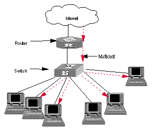
Figure 2-4 IGMP Snooping configuration networking
III. Configuration procedure
Suppose you need to enable IGMP Snooping on VLAN10. The procedures are as follows:
# Display the current state of IGMP Snooping.
<H3C> display igmp-snooping configuration
# If IGMP Snooping is not enabled, enable it in system view.
<H3C> system-view
System View: return to User View with Ctrl+Z.
[H3C] igmp-snooping enable
# Display the status of the VLAN10 interface, to check if PIM or IGMP is enabled on it.
[H3C] display current-configuration interface Vlan-interface 10
# You can enable IGMP Snooping in VLAN view only if PIM or IGMP is not running on VLAN10.
[H3C] vlan10
[H3C-vlan10] igmp-snooping enable
2.6 Troubleshoot IGMP Snooping
Fault: Multicast function cannot be implemented on the switch.
Troubleshooting:
1) IGMP Snooping is disabled.
l Carry out the display current-configuration command in any view to display the status of IGMP Snooping.
l If IGMP Snooping is not enabled, carry out the igmp-snooping enable command in system view to enable IGMP Snooping. Then, use the same command in VLAN view to enable IGMP Snooping in the corresponding VLAN.
2) Multicast forwarding table set up by IGMP Snooping is incorrect.
l Carry out the display igmp-snooping group command in any view to display if the multicast group is the expected one.
l If the multicast group created by IGMP Snooping is not correct, turn to professional maintenance personnel for help.
l Continue with diagnosis 3 if the second step is completed.
3) Multicast forwarding table set up on the bottom layer is incorrect.
l In any view, carry out the display mac-address vlan command to check whether the MAC multicast forwarding table established in the bottom layer by vlan-id is consistent with that established by IGMP Snooping.
l If they are not consistent, please contact the maintenance personnel for help.
Chapter 3 Multicast VLAN Configuration
3.1 Multicast VLAN Overview
Based on the current multicast on demand, when users in different VLANs request the service, multicast flow is duplicated in each VLAN and thus a great deal of bandwidth is wasted. To solve this problem, we provide the multicast VLAN feature. With this feature, you can add switch ports to a multicast VLAN and enable IGMP Snooping to allow users in different VLANs to share the same multicast VLAN. In this way, multicast flow is transmitted in one multicast VLAN instead of multiple user VLANs and bandwidth is greatly saved.
As multicast VLAN is isolated from user VLANs, this guarantees both security and enough bandwidth. After you configure the multicast VLAN, multicast information flow can be transmitted to users continuously.
3.2 Multicast VLAN Configuration
Multicast VLAN is based on layer 2 multicast. The following table describes the multicast VLAN configuration tasks:
Table 3-1 Configure multicast VLAN
|
Item |
Command |
Description |
|
Enter system view |
system-view |
- |
|
Enable IGMP Snooping in system view |
igmp-snooping enable |
Required |
|
Enter VLAN view |
vlan vlan-id |
- |
|
IGMP Snooping is enabled on the VLAN Enable IGMP Snooping in VLAN view |
igmp-snooping enable |
Required |
|
Enable multicast VLAN |
service-type multicast |
Required |
|
Quit VLAN view |
quit |
|
|
Enter the view of the Ethernet port connected to the user |
interface interface-type interface-number |
- |
|
Define the port type to hybrid |
port link-type hybrid |
Required |
|
Add ports to corresponding VLANs |
port hybrid vlan vlan-id-list untagged |
Required |
& Note:
l A port can only belong to one multicast VLAN.
l The type of the ports connected to user terminals must be hybrid untagged.
l The current system supports up to three multicast VLANS.
3.3 Multicast VLAN Configuration Example
I. Network requirements
Configure a multicast VLAN, so that users in VLAN 2 and VLAN 3 receive multicast flows through the multicast VLAN10.
Table 3-2 Device number and description
|
Device |
Description |
Requirement |
|
Switch A |
Layer 3 switch |
The IP address of VLAN 2 interface is 168.10.1.1. The port E1/1/1 belongs to VLAN 2 and is connected to the Workstation The IP address of VLAN 10 interface is 168.20.1.1. The port E1/1/10 belongs to VLAN 10 and is connected to Switch B Configure layer 3 multicast PIM DM and IGMP on VLAN 10 |
|
Switch B |
Layer 2 switch |
VLAN 2 contains the port E1/1/1 and VLAN 3 contains the port E1/1/2. The ports E1/1/1 and E1/1/2 are connected to PC1 and PC2 respectively. The port E1/1/10 is connected to Switch A. |
|
PC 1 |
User 1 |
PC1 is connected to the port E1/1/1 of Switch B. |
|
PC 2 |
User 2 |
PC2 is connected to the port E1/1/2 of Switch B. |
II. Network diagram
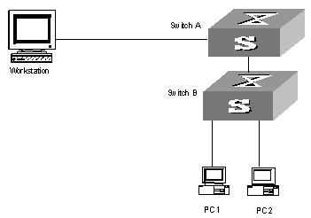
Figure 3-1 Network diagram for multicast VLAN configuration
III. Configuration procedure
Before performing the following configurations, you should configure the IP addresses and connect the devices correctly.
1) Configure Switch A
# Configure the IP address of the VLAN 2 interface to 168.10.1.1. Enable the PIM-DM protocol.
<Switch A> system-view
System View: return to User View with Ctrl+Z.
[Switch A] multicast routing-enable
[Switch A] interface vlan-interface 2
[Switch A-Vlan-interface2] ip address 168.10.1.1 255.255.255.0
[Switch A-Vlan-interface2] pim dm
[Switch A-Vlan-interface2] quit
# Configure the IP address of the VLAN 10 interface to 168.20.1.1. Enable the PIM-DM and IGMP protocols.
[Switch A] interface vlan-interface 10
[Switch A-Vlan-interface10] ip address 168.20.1.1 255.255.255.0
[Switch A-Vlan-interface10] pim dm
[Switch A-Vlan-interface10]igmp enable
[Switch A-Vlan-interface10] quit
# Define Ethernet 1/1/10 as a trunk port and add this port to VLAN 10.
[Switch A]interface Ethernet1/1/10
[Switch A-Ethernet1/1/10]port link-type trunk
[Switch A-Ethernet1/1/10]port trunk permit vlan 10
2) Configure Switch B
# Enable IGMP Snooping.
<Switch B> system-view
System View: return to User View with Ctrl+Z.
[Switch B] igmp-snooping enable
# Enable IGMP-Snooping on VLAN 2 and VLAN 3.
[Switch B] vlan 2
[Switch B-vlan 2] igmp-snooping enable
[Switch B-vlan 2]quit
[Switch B] vlan 3
[Switch B-vlan 3] igmp-snooping enable
# Configure VLAN 10 as multicast VLAN. Enable IGMP Snooping.
[Switch B] vlan 10
[Switch B-vlan10] igmp-snooping enable
[Switch B-vlan10] service-type multicast
[Switch B-vlan10] quit
# Define Ethernet 1/1/10 as trunk port. Add the port to VLAN 10.
[Switch B] interface Ethernet 1/1/10
[Switch B-Ethernet 1/1/10] port link-type trunk
[Switch B-Ethernet 1/1/10] port trunk vlan 10
[Switch B-Ethernet 1/1/10] quit
# Define Ethernet 1/1/1 as hybrid port. Add the port to VLAN 2 and VLAN 10. Make the port carry no VLAN label when it transmits packets of VLAN 2 and VLAN 10. Set the default VLAN ID of the port to VLAN 2.
[Switch B] interface Ethernet 1/1/1
[Switch B-Ethernet 1/1/1] port link-type hybrid
[Switch B-Ethernet 1/1/1] port hybrid vlan 2 10 untagged
[Switch B-Ethernet 1/1/1] port hybrid pvid vlan 2
[Switch B-Ethernet 1/1/1] quit
# Define Ethernet 1/1/2 as hybrid port. Add the port to VLAN 3 and VLAN 10. Make the port carry no VLAN label when it transmits packets of VLAN 3 and VLAN 10. Set the default VLAN ID of the port to VLAN 3.
[Switch B] interface Ethernet 1/1/2
[Switch B-Ethernet 1/1/2] port link-type hybrid
[Switch B-Ethernet 1/1/2] port hybrid vlan 3 10 untagged
[Switch B-Ethernet 1/1/2] port hybrid pvid vlan 3
[Switch B-Ethernet 1/1/2] quit
Chapter 4 Common Multicast Configuration
4.1 Introduction to Common Multicast Configuration
The multicast common configuration is for both the multicast group management protocol and the multicast routing protocol. The configuration includes enabling IP multicast routing, displaying multicast routing table and multicast forwarding table, etc.
4.2 Common Multicast Configuration
Common multicast configuration includes:
l Enabling multicast routing
l Configuring multicast route limit
l Clearing MFC (Multicast Forwarding Cache) forwarding entries or its statistic information
l Configuring managed multicast
l Clearing route entries from the kernel multicast routing table
l Configuring broadcast/multicast suppression
4.2.1 Enabling Multicast Routing
Enable multicast routing first before enabling multicast routing protocol.
Perform the following configuration in system view.
Table 4-1 Enabling multicast routing
|
Operation |
Command |
|
Enable multicast routing |
multicast routing-enable |
|
Disable multicast routing |
undo multicast routing-enable |
By default, multicast routing is disabled.
![]() Caution:
Caution:
Multicast routing must be enabled before other multicast configurations can take effect.
4.2.2 Configuring Multicast Routing Table Size Limit
Because too many multicast routing table entries may exhaust the router memory, you need to limit the size of the multicast routing table.
Perform the following configuration in system view.
Table 4-2 Configuring multicast routing table size limit
|
Operation |
Command |
|
Configure multicast routing table size limit |
multicast route-limit limit |
|
Restore multicast routing table size limit to the default value |
undo multicast route-limit |
By default, the maximum multicast routing table entries is 512.
4.2.3 Clearing MFC Forwarding Entries or Its Statistic Information
You can clear MFC forward entries or statistic information of FMC forward entries via the following command.
Perform the following configuration in user view.
Table 4-3 Clearing MFC forwarding entries or its statistic information
|
Operation |
Command |
|
Clear MFC forwarding entries or its statistic information |
reset multicast forwarding-table [ statistics ] { all | { group-address [ mask { group-mask | group-mask-length } ] | source-address [ mask { source-mask | source-mask-length } ] | incoming-interface { null NULL-interface-number | interface-type interface-number } } * } |
4.2.4 Clearing Route Entries from the Kernel Multicast Routing Table
You can clear route entries from the kernel multicast routing table, as well as MFC forwarding entries via the following command.
Perform the following configuration in user view.
Table 4-4 Clearing routing entries of multicast routing table
|
Operation |
Command |
|
Clear routing entries of multicast routing table |
reset multicast routing-table { all | { group-address [ mask { group-mask | group-mask-length } ] | source-address [ mask { source-mask | source-mask-length } ] | incoming-interface vlan-interface interface-number } * } |
4.3 Managed multicast Configuration
4.3.1 Managed multicast Overview
The managed multicast feature controls user’s authority to join multicast groups. This feature is based on ports: users must first pass the 802.1x authentication set for their ports. Then they are allowed to join the multicast groups specifically configured for them but are prohibited from joining any multicast group they are not authorized to join. In this way, users access to specific multicast groups under control.
Prerequisites of multicast authentication:
1) 802.1x is enabled both globally and on ports. Otherwise, when you enable managed multicast, all IGMP report messages are legal. Then the system allows users to join any group and cannot control the access to multicast groups.
2) The managed multicast is based on port. The 802.1x mode on port must be port authentication. Otherwise, the system discards all IGMP report messages without any processing.
4.3.2 Configuring Managed Multicast
Perform the following configurations in system view.
Table 4-5 Configure managed multicast in system view
|
Operation |
Command |
|
Enable managed multicast |
ip managed-multicast |
|
Disable managed multicast |
undo ip managed-multicast |
Table 4-6 Set managed multicast for users in a specific domain
|
Operation |
Command |
|
Set the multicast group which users in the specified domain are authorized to join |
local-user multicast [ domain domain-name ] ip-address [ mask-length ] |
|
Remove the multicast group which users in the specified domain are authorized to join |
undo local-user multicast [ domain domain-name ] ip-address |
Perform the following configuration in local user view.
Table 4-7 Configure managed multicast in local user view
|
Operation |
Command |
|
Set multicast group which users are authorized to join (managed multicast) |
multicast ip-address [ ip-address &<1-9> ] |
|
Remove the specified managed multicast |
undo multicast { ip-address [ ip-address &<1-9> ] | all } |
![]() Caution:
Caution:
In local user view, before executing this command, you must configure user service type to LAN-ACCESS, which is the only one supported by managed multicast at present.
4.3.3 Managed Multicast Configuration Example
I. Network requirements
As shown in Figure 4-1, HostA and HostB join the multicast group. Layer 3 multicast is enabled on LSA, LSB, LSC and LSD. Managed multicast is enabled on LSA and LSC. Because managed multicast combines multicast with 802.1x, 802.1x must be enabled on LSA and LSC.
II. Network diagram
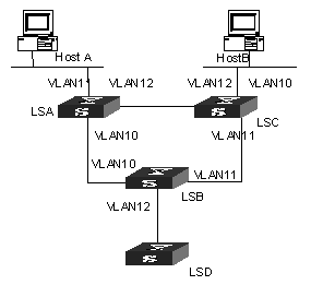
Figure 4-1 Network diagram for managed multicast
III. Configuration procedure
Managed multicast is a module combined with 802.1x, so you need to perform the following configuration beside multicast configuration:
# Enable managed multicast globally.
<H3C>system-view
System View: return to User View with Ctrl+Z.
[H3C] ip managed-multicast
# Enable 802.1x globally.
[H3C] dot1x
# Enable 802.1x on the controlled ports (the access ports for LSA and LSC).
[H3C]interface GigabitEthernet2/1/1
[H3C-GigabitEthernet2/1/1] dot1x
[H3C-GigabitEthernet2/1/1] interface GigabitEthernet2/1/2
[H3C-GigabitEthernet2/1/2] dot1x
# Configure the authentication mode on the controlled ports to port-based mode.
[H3C-GigabitEthernet2/1/2] dot1x –method portbased
[H3C-GigabitEthernet2/1/2] interface GigabitEthernet2/1/1
[H3C-GigabitEthernet2/1/1] dot1x –method portbased
[H3C-GigabitEthernet2/1/1] quit
# Create a local-user in system view. Then set the password and service type for the user.
[H3C] local-user liu
[H3C-luser-liu] password simple aaa
[H3C-luser-liu] service-type lan-access
# In user view, configure the allowed multicast group for the user to join.
[H3C-luser-liu] multicast 227.1.1.1
4.4 Configuring Broadcast/Multicast Suppression
4.4.1 Introduction
To prevent port congestion resulting from broadcast/multicast packet flooding, the switch supports broadcast/multicast suppression. You can enable broadcast/multicast suppression by setting the speed percentage or bandwidth values.
4.4.2 Configuration
Table 4-8 Configuring Broadcast/Multicast Suppression
|
Operation |
Command |
Description |
|
Enter system view |
system-view |
- |
|
Enter Ethernet port view |
interface interface-type interface-number |
Required interface-type must be Ethernet |
|
Configure multicast suppression ration Ethernet port |
multicast-suppression { ratio | bandwidth bandwidth } |
Optional By default, the multicast suppression ratio is 100% |
|
Configure broadcast suppression ration Ethernet port |
broadcast-suppression { ratio | bandwidth bandwidth } |
Optional By default, the broadcast suppression ratio is 50% |
![]() Caution:
Caution:
l You cannot enable both broadcast suppression and multicast suppression simultaneously on the same card. Namely, once you have enabled broadcast suppression on some ports of a card, you cannot enable multicast suppression on the other ports of the card, and vice versa.
l If multicast suppression is enabled, broadcast packets are also suppressed at the same time, while broadcast suppression does not work on multicast suppression.
l No distinction is made between known multicast and unknown multicast for multicast suppression.
4.5 Displaying and Debugging Common Multicast Configuration
After the above configuration, execute display command in any view to display the running of the multicast configuration, and to verify the effect of the configuration.
Execute debugging command in user view for the debugging of multicast.
Table 4-9 Displaying and Debugging Common Multicast Configuration
|
Operation |
Command |
|
Display the multicast routing table |
display multicast routing-table [ group-address [ mask { mask | mask-length } ] | source-address [ mask { mask | mask-length } ] | incoming-interface { vlan-interface vlan-interface-number | register } ]* |
|
Display the multicast forwarding table |
display multicast forwarding-table [ group-address [ mask { mask | mask-length } ] | source-address [ mask { mask | mask-length } ] | incoming-interface { interface-type interface-number | null NULL-interface- number | register } ]* |
|
View port-specific multicast forwarding table n\information |
display mpm forwarding-table [ group-address | source-address ] |
|
View IP multicast group and MAC multicast group information of all VLANs or a specific VLAN |
display mpm group [ vlan vlan-id [ ip-address ] ] |
|
Enable multicast packet forwarding debugging |
debugging multicast forwarding |
|
Disable multicast packet forwarding debugging |
undo debugging multicast forwarding |
|
Enable multicast forwarding status debugging |
debugging multicast status-forwarding |
|
Disable multicast forwarding status debugging |
undo debugging multicast status-forwarding |
|
Enable multicast kernel routing debugging |
debugging multicast kernel-routing |
|
Disable multicast kernel routing debugging |
undo debugging multicast kernel-routing |
The multicast routing tables can be layered as follows:
l Each multicast routing protocol has a multicast routing table of itself.
l All the multicast routing tables can be summarized into the multicast kernel routing tables.
l The multicast kernel routing tables should keep consistent with the multicast forwarding tables which actually control the forwarding of the multicast data packets.
The multicast forwarding tables are mainly used for debugging. Usually, users can view the multicast kernel routing tables to get the required information.
Chapter 5 IGMP Configuration
5.1 IGMP Overview
5.1.1 Introduction to IGMP
Internet Group Management Protocol (IGMP) is a protocol in the TCP/IP suite responsible for management of IP multicast members. It is used to establish and maintain multicast membership among IP hosts and their directly connected neighboring routers. IGMP excludes transmitting and maintenance of membership information among multicast routers, which are completed by multicast routing protocols. All hosts participating in multicast must implement IGMP.
Hosts participating in IP multicast can join and leave a multicast group at any time. The number of members of a multicast group can be any integer and the location of them can be anywhere. A multicast router does not need and cannot keep the membership of all hosts. It only uses IGMP to learn whether receivers (i.e., group members) of a multicast group are present on the subnet connected to each interface. A host only needs to keep which multicast groups it has joined.
IGMP is not symmetric on hosts and routers. Hosts need to respond to IGMP query messages from the multicast router, i.e., report the group membership to the router. The router needs to send membership query messages periodically to discover whether hosts join the specified group on its subnets according to the received response messages. When the router receives the report that hosts leave the group, the router will send a group-specific query packet (IGMP Version 2) to discover whether no member exists in the group.
Up to now, IGMP has three versions, namely, IGMP Version 1 (defined by RFC1112), IGMP Version 2 (defined by RFC2236) and IGMP Version 3. At present, IGMP Version 2 is the most widely used version.
IGMP Version 2 boasts the following improvements over IGMP Version 1:
I. Election mechanism of multicast routers on the shared network segment
A shared network segment means that there are multiple multicast routers on a network segment. In this case, all routers running IGMP on the network segment can receive the membership report from hosts. Therefore, only one router is necessary to send membership query messages. In this case, the router election mechanism is required to specify a router as the querier.
In IGMP Version 1, selection of the querier is determined by the multicast routing protocol. While IGMP Version 2 specifies that the multicast router with the lowest IP address is elected as the querier when there are multiple multicast routers on the same network segment.
II. Leaving group mechanism
In IGMP Version 1, hosts leave the multicast group quietly without informing the multicast router. In this case, the multicast router can only depend on the timeout of the response time of the multicast group to confirm that hosts leave the group. In Version 2, when a host is intended to leave, it will send a leave group message if it is the host who responds to the latest membership query message.
III. Specific group query
In IGMP Version 1, a query of a multicast router is targeted at all the multicast groups on the network segment, which is known as General Query.
In IGMP Version 2, Group-Specific Query is added besides general query. The destination IP address of the query packet is the IP address of the multicast group. The group address domain in the packet is also the IP address of the multicast group. This prevents the hosts of members of other multicast groups from sending response messages.
IV. Max response time
The Max Response Time is added in IGMP Version 2. It is used to dynamically adjust the allowed maximum time for a host to respond to the group query message.
5.1.2 Introduction to IGMP Proxy
For a large scale PIM-DM (protocol independent multicast-dense mode) network with multicast routing protocol employed, many leaf networks may exist (a leaf network here refers to an end node of a multicast forwarding tree, it is a subnet that contains multicast clients only). It is a heavy load to configure and manage all these leaf networks.
You can ease the workload of configuring and managing leaf networks without affecting the multicast connections in them by enabling IGMP proxy on devices in these leaf networks.
After IGMP proxy is configured, the devices in leaf networks act as a host to the exterior network. They receive the multicast data of the associated group only when some of the hosts directly connected to them are multicast group members.
I. Description of IGMP proxy configuration
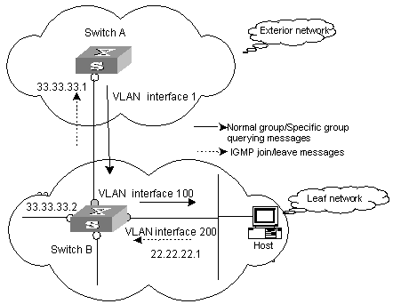
Figure 5-1 A schematic diagram of IGMP proxy
Figure 5-1 illustrates how IGMP proxy works. In this figure:
1) Switch B is configured as follows:
l Multicast is enabled.
l PIM and IGMP are configured on the interfaces of VLAN 100 and VLAN 200.
l The interface of VLAN 100 is configured as the IGMP proxy interface of the interface of VLAN 200.
2) witch A is configured as follows:
l Multicast is enabled.
l PIM and IGMP are configured on the interface of VLAN 100.
l The pim neighbor-policy command is executed in VLAN 100 interface view to filter the PIM neighbors of the network segment 33.33.33.0/24. That is, prevent Switch B from being the PIM neighbor.
II. Operating mechanism of IGMP Proxy
The procedures to process IGMP join/leave messages are as follows:
l After receiving an IGMP join/leave message sourced from a host through the interface of VLAN 200, Switch B changes the source address of the message to the IP address of VLAN 100 interface (33.33.33.2), which is the outbound interface leading to Switch A.
l Switch B sends the IGMP message to Switch A.
l Switch A processes the message after receiving the IGMP message sent by Switch B through the interface of VLAN 100, just as the message is sent by a host directly connected to the interface of VLAN 100.
The procedures to process IGMP normal group or specific group querying messages are as follows:
l After receiving a normal group or a specific group querying message from Switch A, Switch B changes the source address of the querying message to the address of the outbound interface leading to hosts.
l Switch B transmits the message through the interface of VLAN 200.
5.2 IGMP Configuration
After the multicast function is enabled, you must enable IGMP on the interface first and then perform other IGMP configurations.
1) IGMP basic configuration includes:
l Enabling multicast
l Enabling IGMP on an interface
2) IGMP advanced configuration includes:
l Configuring a router to join specified multicast group
l Configuring the IGMP query message interval
l Configuring the IGMP version
l Configuring the IGMP querier present timer
l Configuring the maximum query response time
l Configuring the times of sending IGMP Group-Specific Query packet
l Configuring the interval of sending IGMP Group-Specific Query packet
l Configuring the limit of IGMP groups on an interface
l Deleting IGMP Groups Joined on an Interface
l Configuring the Filtering Rule of Multicast Groups
l Enabling/Disabling IGMP Fast Leaving
5.2.1 Enabling Multicast
Only if the multicast function is enabled can the multicast-related configurations take effect.
Refer to 4.2.1 Enabling Multicast Routing.
5.2.2 Enabling IGMP on an Interface
This configuration task is to enable IGMP on the interface which needs to maintain the multicast membership. After this, you can initiate IGMP feature configuration.
Perform the following configuration in VLAN interface view.
Table 5-1 Enabling/Disabling IGMP on an interface
|
Operation |
Command |
|
Enable IGMP on an interface |
igmp enable |
|
Disable IGMP on an interface |
undo igmp enable |
![]() Caution:
Caution:
l If the VLAN VPN is enabled on a port, the IGMP Snooping feature cannot be enabled on the VLAN for the port or the IGMP feature cannot be enabled on the corresponding VLAN interface.
l If IGMP Snooping feature is enabled on a VLAN, or IGMP is enabled on the VLAN interface, you cannot add the member port on which VLAN VPN is enabled into the VLAN.
By default, IGMP is not enabled.
5.2.3 Configuring the IGMP Version
Perform the following configuration in VLAN interface view.
Table 5-2 Configuring the IGMP version
|
Operation |
Command |
|
Select the IGMP version that the router uses |
igmp version { 2 | 1 } |
|
Restore the default setting |
undo igmp version |
By default, IGMP Version 2 is used.
![]() Caution:
Caution:
The system does not support automatic switching between different IGMP versions. Therefore, all routers on a subnet must be configured to run the IGMP version.
5.2.4 Configuring the Interval to Send IGMP Query Message
Multicast routers send IGMP query messages to discover which multicast groups are present on attached networks. Multicast routers send query messages periodically to refresh their knowledge of members present on their networks.
Perform the following configuration in VLAN interface view.
Table 5-3 Configuring the interval to send IGMP query message
|
Operation |
Command |
|
Configure the interval to send IGMP query message |
igmp timer query seconds |
|
Restore the default value |
undo igmp timer query |
When there are multiple multicast routers on a network segment, the querier is responsible for sending IGMP query messages to all hosts on the LAN.
By default, the interval is 60 seconds.
5.2.5 Configuring the Interval and the Number of Querying IGMP Packets
On the shared network, it is the query router (querier) that maintains IGMP membership on the interface. The igmp lastmember-queryinterval and igmp robust-count commands are used to configure the interval and times of sending IGMP group-specific query packets for the querier when it receives an IGMP leave message from a host.
l The host sends the IGMP Leave message.
l Upon receiving the message, IGMP querier sends the group-specific IGMP query message for specified times (defined by the robust-value in igmp robust-count, with the default value being 2) and at a time interval (defined by the seconds in igmp lastmember-queryinterval, with the default value being 1 second).
l When other hosts receive the message from the IGMP querier and are interested in this group, they return the IGMP Membership Report message within the defined maximum response time.
l If IGMP querier receives the report messages from other hosts within the period equal to robust-value ´ seconds, it continues membership maintenance for this group.
l If it receives no report message from any other host within this period, it reckons this as timeout and ends membership maintenance for this group.
This configuration takes effect only when the querier runs IGMP version 2. If a host runs IGMP Version 1, it does not send IGMP Leave Group message when it leaves a group. In this case, this configuration does not work for the host.
Please perform the following configurations in VLAN interface view.
I. Configuring interval for querying IGMP packets
Table 5-4 Configuring interval for querying IGMP packets
|
Operation |
Command |
|
Configure interval for querying IGMP packets |
igmp lastmember-queryinterval seconds |
|
Restore the default query interval |
undo igmp lastmember-queryinterval |
By default, the interval is 1 second.
II. Configuring the number of last member querying
Table 5-5 Configuring the number of last member querying
|
Operation |
Command |
|
Configure number of last member querying |
igmp robust-count robust-value |
|
Restore the default number of querying |
undo igmp robust-count |
By default, an IGMP group-specific query message is sent for twice.
5.2.6 Configuring the Present Time of IGMP Querier
On shared network, namely a network segment where multiple multicast routers exist, a query router (querier for short) sends query messages on the interface regularly. If a non-query router fails to receive messages from the querier within a period of time, it will deem that the querier has failed and take over the job of the original querier.
In the IGMP V1 version, the querier selection is determined by the multicast routing protocol; in the IGMP V2 version, the router with the lowest IP address on a shared network segment acts as the querier.
The IGMP querier presence time is the period of time before the router takes over as the querier sending query messages, after the previous querier has stopped doing so.
Perform the following configuration in VLAN interface view.
Table 5-6 Configuring the present time of IGMP querier
|
Operation |
Command |
|
Change the present time of IGMP querier |
igmp timer other-querier-present seconds |
|
Restore the default value |
undo igmp timer other-querier-present |
By default, the value is twice the IGMP query message interval, namely 120 seconds.
5.2.7 Configuring Maximum Response Time for IGMP Query Message
When a router receives a query message, the host will set a timer for each multicast group it belongs to. The value of the timer is randomly selected between 0 and the maximum response time. When any timer becomes 0, the host will send the membership report message of the multicast group.
Setting the maximum response time reasonably can enable the host to respond to query messages quickly. In this case, the router can fast master the existing status of the members of the multicast group.
Perform the following configuration in VLAN interface view.
Table 5-7 Configuring the maximum response time for IGMP query message
|
Operation |
Command |
|
Configure the maximum response time for IGMP query message |
igmp max-response-time seconds |
|
Restore the maximum query response time to the default value |
undo igmp max-response-time |
The smaller the maximum query response time value, the faster the router prunes groups. The actual response time is a random value in the range from 1 to 25 seconds. By default, the maximum query response time is 10 seconds.
5.2.8 Configuring the limit of IGMP groups on an interface
If there is no limit to the number of IGMP groups added on a router interface or a router, the router memory may be exhausted, which may cause router failure.
You can set number limit for the IGMP groups added on the interface, but not the number limit for the IGMP groups added in the router, which is defined by the system.
Perform the following configuration in VLAN interface view.
Table 5-8 Configuring the limit of IGMP groups on an interface
|
Operation |
Command |
|
Configure the limit of IGMP groups on an interface |
igmp group-limit limit |
|
Restore the limit of IGMP groups on an interface to the default value |
undo igmp group-limit |
By default, the maximum number of IGMP groups on an interface is 512.
5.2.9 Configuring a Router to Join Specified Multicast Group
Usually, the host operating IGMP will respond to IGMP query packet of the multicast router. In case of response failure, the multicast router will consider that there is no multicast member on this network segment and will cancel the corresponding path. Configuring one interface of the router as multicast member can avoid such problem. When the interface receives IGMP query packet, the router will respond, thus ensuring that the network segment where the interface located can normally receive multicast packets.
For an Ethernet switch, you can configure a port in a VLAN interface to join a multicast group.
Perform the following configuration in the corresponding view.
Table 5-9 Configuring a router to join specified multicast group
|
Operation |
Command |
|
Configure the router to join a specified multicast group (in VLAN interface view) |
igmp host-join group-address port interface-type interface-number [ to interface-type interface- number ] |
|
Cancel the configuration (in VLAN interface view) |
undo igmp host-join group-address port interface-type interface- num [ to interface-type interface-number ] |
|
Configure the router to join a specified multicast group (in Ethernet port view) |
igmp host-join group-address vlan vlan-id |
|
Cancel the configuration (in Ethernet port view) |
undo igmp host-join group-address vlan vlan-id |
& Note:
The above two configuration methods have the same result (both takes effect on port). You can select either of them.
By default, a router joins no multicast group. Note that the specified port must belong to this VLAN interface on which IGMP is enabled. Otherwise, the configuration does not take effect.
5.2.10 Deleting IGMP Groups Joined on an Interface
This configuration task is to delete all IGMP groups joined on all interfaces or specific interfaces of the router, or to delete the IGMP groups at the specific address or in the specific network segment on the specific interfaces of the router.
Perform the following configuration in user view.
Table 5-10 Deleting IGMP groups joined on an interface
|
Operation |
Command |
|
Delete IGMP groups joined on an interface |
reset igmp group { all | interface vlan-interface interface-number { all | group-address [ group-mask ] } } |
After a group is deleted, if other IGMP membership report messages occur, the interfaces can join the corresponding group again.
5.2.11 Configuring the Filtering Rule of Multicast Groups
On the IGMP snooping-enabled switch, you can configure ACL rules whether the specified multicast group can be joined to a VLAN or not. This feature filters every received IGMP join packet. According to the destination group address of the packets and the ACL rule bound to the VLAN, the switch determines whether to discard the packets or let them pass.
By setting the filtering rule of multicast groups in the VLAN, you can control access to IP multicast groups. You can only configure one ACL rule for each VLAN, and the new configured rule will replace the old one.
Perform the following configuration in VLAN view.
Table 5-11 Configure the aging time of multicast group members
|
Operation |
Command |
|
Set the filtering rule of multicast groups in the specified VLAN |
igmp-snooping group-policy acl-number |
|
Cancel the filtering rule of multicast groups in the specified VLAN |
undo igmp-snooping group-policy |
By default, no filtering rule is set for a VLAN. In this case, a host can be joined to any multicast group.
![]() Caution:
Caution:
l If an inexistent acl-number is bound to the VLAN, or if the bound acl-number is not configured with a rule, a host is still allowed to join any multicast group.
l If no acl-number exists, you can also configure the filtering rule of multicast groups in VLAN view. That is, this rule is not restricted by the ACL itself, and is valid for all members in the specified VLAN.
5.2.12 Enabling/Disabling IGMP Fast Leaving
An IGMP-enabled Layer 3 switch does not query packets of the specific multicast group to a fast leave-enabled port any longer when the port receives an IGMP leave packet. Instead, the switch removes the port from the outbound port lists of all Layer 3 multicast forwarding tables that are of the same multicast group to peel off the port from the multicast group. That is, the switch does not forward multicast data to the port.
Perform the following configuration in Ethernet port view or system view.
Table 5-12 Enable/Disable IGMP fast leave
|
Operation |
Command |
Remarks |
|
Enter system view |
system-view |
- |
|
Enable IGMP fast leave in system view |
igmp fast-leave [ vlan { vlan-id [ to vlan-id ] } &<1-10> ] |
IGMP fast leave is disabled by default |
|
Enter Ethernet port view |
interface interface-type interface-number |
- |
|
Enable IGMP fast leave in Ethernet port view |
igmp fast-leave [ vlan { vlan-id [ to vlan-id ] } &<1-10> ] |
IGMP fast leave is disabled by default |
|
Disable IGMP fast leave |
undo igmp fast-leave [ vlan { vlan-id [ to vlan-id ] } &<1-10> ] |
- |
For detailed configuration, refer to the H3C S9500 Series Routing Switches Command Manual.
& Note:
l Fast leaves that are configured in system view and Ethernet port view operate separately.
l The configuration made in system view will be effective to ports within all the specified VLANs, while the configuration in port view will be effective to the port within the specific VLANs (for example, when a trunk port belongs to multiple VLANs).
![]() Caution:
Caution:
l If the specified VLANs do not exists, the port does not belongs to any of the specified VLANs, or the VLANs do not have IGMP enabled, you can still configure the fast leave feature, but the configuration will not take effect.
l You must enable multicast routing globally by executing the multicast routing-enable command in system view before you can configure the fast leave feature.
l If global multicast routing is disabled, all existing IGMP fast leave-related configurations will be cleared.
l When you configure IGMP fast leave on aggregation ports, the configuration takes effect only on primary aggregation ports.
l If you have added an IGMP V1 host of the same multicast group to the port, or configured a static host of the same multicast group by using the igmp host-join command, the switch does not remove the port when the port receives an IGMP Leave packet of the multicast group even if you have enabled IGMP fast leave for the port.
5.3 IGMP Proxy Configuration
5.3.1 Prerequisites
l The related interfaces of the devices in the exterior network have IP addresses, PIM, and IGMP configured.
l The switches in the leaf networks are multicast-enabled. The related ports are added to specific VLANs. The interfaces of these VLANs have IP addresses, PIM, and IGMP configured.
5.3.2 Configuration Procedure
Table 5-13 Configure IGMP proxy
|
Operation |
Command |
Description |
|
Enter system view |
system-view |
- |
|
Enter VLAN interface view |
interface vlan-interface vlan-id |
- |
|
Enable IGMP proxy for the current VLAN interface and specify the proxy interface for the VLAN interface |
igmp proxy interface-type interface-number |
Required For a VLAN interface, IGMP proxy is disabled by default. |
![]() Caution:
Caution:
l You need to enable PIM protocol for a VLAN interface before executing the igmp proxy command in its VLAN interface view.
l If you configure the IGMP proxy interface for a VLAN interface multiple times, the latest configured IGMP proxy interface will be effective.
l A VLAN interface cannot be the IGMP proxy interfaces of two or more other VLAN interfaces simultaneously.
5.3.3 IGMP Configuration Example
I. Network requirements
As shown in Figure 5-2, Switch B resides in a leaf network. Configure IGMP proxy for Switch B to ease the configuration and management work load in the leaf network without affecting multicast connections in it.
You need to perform the following configurations to meet the requirements:
l Enable IGMP and PIM-DM for the related VLAN interfaces on Switch A.
l Enable multicast on Switch B. Enable PIM for the interfaces of VLAN 100 and VLAN 200. Configure the interface of VLAN 100 to be the proxy interface of the interface of VLAN 200.
& Note:
The following depicts IGMP and IGMP proxy configuration (other related configuration is not covered here).
II. Network diagram
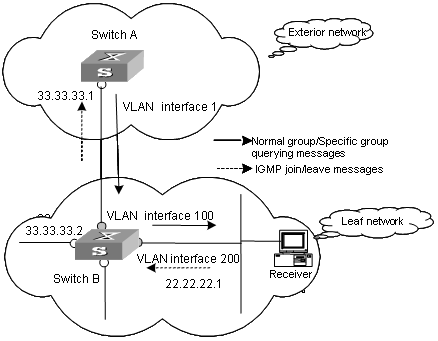
Figure 5-2 Network diagram for IGMP proxy configuration
III. Configuration steps
1) Configure Switch B.
# Enable multicast.
<SwitchB>system-view
System View: return to User View with Ctrl+Z.
[SwitchB] multicast routing-enable
# Create VLAN 200 and VLAN 100. Add related ports to the corresponding VLANs. Enable IGMP and PIM-DM for the interfaces on Vlan-interface200 and Vlan-interface 100.
[SwitchB]interface vlan-interface 200
[SwitchB-Vlan-interface 200] ip address 22.22.22.1 24
[SwitchB-Vlan-interface 200] igmp enable
[SwitchB-Vlan-interface 200] pim dm
[SwitchB-Vlan-interface 200] igmp host-join 224.0.1.1 port Ethernet 3/0/8
[SwitchB] interface vlan-interface 100
[SwitchB-Vlan-interface 100] ip address 33.33.33.2 24
[SwitchB-Vlan-interface 100] igmp enable
[SwitchB-Vlan-interface 100] pim dm
[SwitchB-Vlan-interface 100] quit
# Configure the interface of VLAN 100 to be the IGMP proxy interface of the interface of VLAN 200.
[SwitchB] interface vlan-interface 200
[SwitchB-Vlan-interface 200] igmp proxy Vlan-interface 100
2) Configure Switch A.
# Enable multicast.
<SwitchA>system-view
System View: return to User View with Ctrl+Z.
[SwitchA] multicast routing-enable
# Enable IGMP and PIM-DM for the interface of VLAN 100.
[SwitchA] interface vlan-interface 100
[SwitchA-Vlan-interface 100] igmp enable
[SwitchA-Vlan-interface 100] pim dm
# Configure Vlan-interface 100 so that it will not use the IP address 33.33.33.2 as a PIM neighbor
[SwitchA-Vlan-interface 100] pim neighbor-policy 2001
[SwitchA-Vlan-interface 100] quit
[SwitchA] acl number 2001
[SwitchA-acl-basic-2001] rule deny source 33.33.33.2 0
[SwitchA-acl-basic-2001] rule permit source any
3) Configure Receiver.
Receiver establishes HTTP connections to the multicast source and sends the list of the names of the services provided by the multicast source to the clients (Each service has its own multicast address, which is the multicast group). When a service is selected, the client sends IGMP packets to join the multicast group, through which the receiver can receive the corresponding multicast packets.
5.4 Displaying and Debugging IGMP
After the above configuration, execute display command in any view to display the running of IGMP configuration, and to verify the effect of the configuration.
Execute debugging command in corresponding views for the debugging of IGMP.
Table 5-14 Displaying and debugging IGMP
|
Operation |
Command |
|
Display the information about members of IGMP multicast groups |
display igmp group [ group-address | interface vlan-interface interface-number ] |
|
Display the IGMP configuration and running information about the interface |
display igmp interface [ vlan-interface interface-number ] |
|
Enable the IGMP information debugging |
debugging igmp { all | event | host | packet | timer } |
|
Disable the IGMP information debugging |
undo debugging igmp { all | event | host | packet | timer } |
Chapter 6 PIM-DM Configuration
6.1 PIM-DM Overview
6.1.1 Introduction to PIM-DM
PIM-DM (Protocol Independent Multicast, Dense Mode) belongs to dense mode multicast routing protocols. PIM-DM is suitable for small networks. Members of multicast groups are relatively dense in such network environments.
6.1.2 PIM-DM Working Principle
The working procedures of PIM-DM include neighbor discovery, flood & prune and graft.
I. Neighbor discovery
The PIM-DM router needs to use Hello messages to perform neighbor discovery when it is started. All network nodes running PIM-DM keep in touch with one another with Hello messages, which are sent periodically.
II. Flood&Prune
PIM-DM assumes that all hosts on the network are ready to receive multicast data. When a multicast source "S" begins to send data to a multicast group "G", after the router receives the multicast packets, the router will perform RPF check according to the unicast routing table first. If the RPF check is passed, the router will create an (S, G) entry and then flood the data to all downstream PIM-DM nodes. If the RPF check is not passed, that is, multicast packets enter from an error interface, the packets will be discarded. After this process, an (S, G) entry will be created in the PIM-DM multicast domain.
If the downstream node has no multicast group members, it will send a Prune message to the upstream nodes to inform the upstream node not to forward data to the downstream node. Receiving the prune message, the upstream node will remove the corresponding interface from the outgoing interface list corresponding to the multicast forwarding entry (S, G). In this way, a SPT (Shortest Path Tree) rooted at Source S is built. The pruning process is initiated by leaf routers first.
This process is called “flood & prune” process. In addition, nodes that are pruned provide timeout mechanism. Each router re-starts the “flood & prune” process upon pruning timeout. The consistent “flood & prune” process of PIM-DM is performed periodically.
During this process, PIM-DM uses the RPF check and the existing unicast routing table to build a multicast forwarding tree rooted at the data source. When a packet arrives, the router will first judge the correctness of the path. If the interface that the packet arrives is the one indicated by the unicast routing to the multicast source, the packet is regarded to be from the correct path. Otherwise, the packet will be discarded as a redundancy packet without the multicast forwarding. The unicast routing information as path judgment can come from any unicast routing protocol independent of any specified unicast routing protocol such as the routing information learned by RIP and OSPF
III. Assert mechanism
As shown in the following figure, both routers A and B on the LAN have their own receiving paths to multicast source S. In this case, when they receive a multicast packet sent from multicast source S, they will both forward the packet to the LAN. Multicast Router C at the downstream node will receive two copies of the same multicast packet.
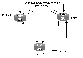
Figure 6-1 Assert mechanism diagram
When they detect such a case, routers need to select a unique sender by using the assert mechanism. Routers will send Assert packets to select the best path. If two or more than two paths have the same priority and metric, the path with a higher IP address will be the upstream neighbor of the (S, G) entry, which is responsible for forwarding the (S, G) multicast packet.
& Note:
Currently assert mechanism is not available on the H3C S9500 Series Routing Switches.
IV. Graft
When the pruned downstream node needs to be restored to the forwarding state, the node will send a graft packet to inform the upstream node.
6.2 PIM-DM Configuration
1) PIM-DM basic configuration includes:
l Enabling multicast
l Enabling PIM-DM
2) PIM-DM advanced configuration includes:
l Configuring the time interval for ports to send Hello packets
l Entering the PIM view
l Configuring filtering of multicast source/group
l Configuring filtering of PIM neighbor
l Configuring the maximum number of PIM neighbor on an interface
l Clearing PIM neighbors
6.2.1 Enabling Multicast
Refer to 4.2.1 Enabling Multicast Routing.
6.2.2 Enabling PIM-DM
PIM-DM needs to be enabled in configuration of all interfaces.
After PIM-DM is enabled on an interface, it will send PIM Hello messages periodically and process protocol packets sent by PIM neighbors.
Perform the following configuration in VLAN interface view.
|
Operation |
Command |
|
Enable PIM-DM on an interface |
pim dm |
|
Disable PIM-DM on an interface |
undo pim dm |
It’s recommended to configure PIM-DM on all interfaces in non-special cases. This configuration is effective only after the multicast routing is enabled in system view.
Once enabled PIM-DM on an interface, PIM-SM cannot be enabled on the same interface and vice versa.
6.2.3 Configuring the Time Intervals for Ports to Send Hello Packets
When protocol independent multicast (PIM) protocol is enabled for a port, the port sends Hello packets periodically. The time intervals to send Hello packets vary with the bandwidth and type of the connected networks.
Perform the following configuration in VLAN interface view.
Table 6-2 Configure the time intervals for ports to send Hello packets
|
Operation |
Command |
|
Configure the time intervals for ports to send Hello packets |
pim timer hello seconds |
|
Restore the default values of the time intervals |
undo pim timer hello |
You can configure different time intervals according to the actual networks. By default, the time interval for sending Hello packets is 30 seconds. In general, you need not modify the parameter seconds.
& Note:
l The time interval can be configured only after the PIM protocol such as protocol independent multicast-dense mode (PIM-DM) protocol or protocol independent multicast-sparse mode (PIM-SM) protocol is enabled in VLAN interface view.
l When you configure the time interval for a port to send Hello packets, the pim neighbor hold-time value automatically turns into 3.5 times the time interval value. Therefore you need not configure a value for pim neighbor hold-time.
6.2.4 Entering the PIM View
Global parameters of PIM should be configured in PIM view.
Perform the following configuration in system view.
|
Operation |
Command |
|
Enter PIM view |
pim |
|
Back to system view |
undo pim |
Using undo pim command, you can clear the configuration in PIM view, and back to system view.
6.2.5 Configuring the Filtering of Multicast Source/Group
You can set to filter the source (and group) address of multicast data packets via this command. When this feature is configured, the router filters not only multicast data, but the multicast data encapsulated in the registration packets.
Perform the following configuration in the PIM view.
Table 6-4 Configuring the filtering of multicast source/group
|
Operation |
Command |
|
Configure the filtering of multicast source/group |
source-policy acl-number |
|
Remove the configuration of filtering |
undo source-policy |
If resource address filtering is configured, as well as basic ACLs, then the router filters the resource addresses of all multicast data packets received. Those not matched will be discarded.
If resource address filtering is configured, as well as advanced ACLs, then the router filters the resource and group addresses of all multicast data packets received. Those not matched will be discarded.
This command also filters multicast data encapsulated in registration packets.
If this command is executed for a second time, the previous configuration will be overwritten by the new configuration.
6.2.6 Configuring the Filtering of PIM Neighbor
You can configure basic ACLs to filter the routers which can be PIM neighbors of the current interface.
Perform the following configuration in the VLAN interface view.
Table 6-5 Configuring the filtering of PIM neighbor
|
Operation |
Command |
|
Configure filtering of PIM neighbor |
pim neighbor-policy acl-number |
|
Remove the configuration of filtering |
undo pim neighbor-policy |
6.2.7 Configuring the Maximum Number of PIM Neighbor on an Interface
The maximum number of PIM neighbors of a router interface can be configured to avoid exhausting the memory of the router or router faults. The maximum number of PIM neighbors of a router is defined by the system, and is not open for modification.
Perform the following configuration in the VLAN interface view.
Table 6-6 Configuring the maximum number of PIM neighbor on an interface
|
Operation |
Command |
|
Configure the maximum number of PIM neighbor on an interface |
pim neighbor-limit limit |
|
Restore the limit of PIN neighbor to the default value |
pim neighbor-limit |
By default, the PIM neighbors on the interface are limited to 128.
If the number of PIM neighbors of an interface has exceeded the configured value by the time of configuration, the existing PIM neighbors will not be deleted.
6.2.8 Clearing PIM Routing Table Entries
Perform the following configuration in user view.
Table 6-7 Clearing multicast route entries from PIM routing table
|
Operation |
Command |
|
Clear multicast route entries from PIM routing table |
reset pim routing-table { all | { group-address [ mask { group-mask | group-mask-length } ] | source-address [ mask { source-mask | source-mask-length } ] | { incoming-interface interface-type interface-number | null } } * } |
6.2.9 Clearing PIM Neighbors
Perform the following configuration in user view.
Table 6-8 Resetting PIM neighbor
|
Operation |
Command |
|
Clear PIM neighbors |
reset pim neighbor { all | { neighbor-address | interface interface-type interface-number } * } |
6.3 Displaying and Debugging PIM-DM
After the above configuration, execute display command in any view to display the running of PIM-DM configuration, and to verify the effect of the configuration.
Execute debugging command in user view for the debugging of PIM-DM.
Table 6-9 Displaying and debugging PIM-DM
|
Operation |
Command |
|
Display the PIM multicast routing table |
display pim routing-table [ { { *g [ group-address [ mask { mask-length | mask } ] ] | **rp [ rp-address [ mask { mask-length | mask } ] ] } | { group-address [ mask { mask-length | mask } ] | source-address [ mask { mask-length | mask } ] } * } | incoming-interface interface-type interface-number | null } | { dense-mode | sparse-mode } ] * |
|
Display the PIM interface information |
display pim interface [ Vlan-interface Vlan-interface-number ] |
|
Display the information about PIM neighboring routers |
display pim neighbor [ interface Vlan-interface Vlan-interface-number ] |
|
Display BSR information |
display pim bsr-info |
|
Display RP information |
display pim rp-info [ group-address ] |
|
Enable the PIM debugging |
debugging pim common { all | event | packet | timer } |
|
Disable the PIM debugging |
undo debugging pim common { all | event | packet | timer } |
|
Enable the PIM-DM debugging |
debugging pim dm { alert | all | mbr | mrt | timer | warning | { recv | send } { all | assert | graft | graft-ack | join | prune } } |
|
Disable the PIM-DM debugging |
undo debugging pim dm { alert | all | mbr | mrt | timer | warning | { recv | send } { all | assert | graft | graft-ack | join | prune } } |
6.4 PIM-DM Configuration Example
I. Networking requirements
Lanswitch1 is connected to the multicast source through VLAN-interface 10, connected to Lanswitch2 through VLAN-interface 11 and connected to Lanswitch3 through VLAN-interface 12. Through running PIM-DM, you can implement multicast among RECEIVER 1, RECEIVER 12 and Multicast Source.
II. Networking diagram
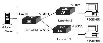
Figure 6-2 PIM-DM configuration networking
III. Configuration procedure
This section only introduces Lanswitch1 configuration procedure, while Lanswitch2 and Lanswitch3 configuration procedures are similar.
# Enable the multicast routing.
<H3C>system-view
System View: return to User View with Ctrl+Z.
[H3C] multicast routing-enable
# Enable IGMP and PIM-DM on the interface.
[H3C] vlan 10
[H3C-vlan10] port ethernet 2/1/2
[H3C-vlan10] quit
[H3C] vlan 11
[H3C-vlan11] port ethernet 2/1/4
[H3C-vlan11] quit
[H3C] vlan 12
[H3C-vlan12] port ethernet 2/1/6
[H3C-vlan12] quit
[H3C] interface vlan-interface 10
[H3C-vlan-interface10] ip address 1.1.1.1 255.255.0.0
[H3C-vlan-interface10] igmp enable
[H3C-vlan-interface10] pim dm
[H3C-vlan-interface10] quit
[H3C] interface vlan-interface 11
[H3C-vlan-interface11] ip address 2.2.2.2 255.255.0.0
[H3C-vlan-interface11] igmp enable
[H3C-vlan-interface11] pim dm
[H3C-vlan-interface11] quit
[H3C] interface vlan-interface 12
[H3C-vlan-interface12] ip address 3.3.3.3 255.255.0.0
[H3C-vlan-interface11] igmp enable
[H3C-vlan-interface12] pim dm
& Note:
You should enable PIM-DM on all equal-cost routes if there are any.
Chapter 7 PIM-SM Configuration
7.1 PIM-SM Overview
7.1.1 Introduction to PIM-SM
PIM-SM (Protocol Independent Multicast, Sparse Mode) belongs to sparse mode multicast routing protocols. PIM-SM is mainly applicable to large-scale networks with broad scope in which group members are relatively sparse.
Different from the flood & prune principle of the dense mode, PIM-SM assumes that all hosts do not need to receive multicast packets, unless there is an explicit request for the packets.
PIM-SM uses the RP (Rendezvous Point) and the BSR (Bootstrap Router) to advertise multicast information to all PIM-SM routers and uses the join/prune information of the router to build the RP-rooted shared tree (RPT), thereby reducing the bandwidth occupied by data packets and control packets and reducing the process overhead of the router. Multicast data flows along the shared tree to the network segments the multicast group members are on. When the data traffic is sufficient, the multicast data flow can switch over to the SPT (Shortest Path Tree) rooted on the source to reduce network delay. PIM-SM does not depend on the specified unicast routing protocol but uses the present unicast routing table to perform the RPF check.
Note that, the creation and interaction of the RPs and BSRs are implemented through periodical RP advertisements and BSR Bootstrap packets respectively. You can view the packets in the following debugging information:
<H3C> debugging pim sm send ?
assert PIM-SM assertion packet sending debugging functions
bootstrap PIM-SM bootstrap packet sending debugging functions
crpadv PIM-SM RP candidate advertisement sending debugging functions
jp PIM-SM join/prune packet sending debugging functions
reg PIM-SM registration packet sending debugging functions
regstop PIM-SM registration-stop packet sending debugging functions
To make PIM-SM operate, you must configure candidate RPs and BSRs. BSRs collect and broadcast the information from candidate RPs.
7.1.2 PIM-SM Working Principle
The PIM-SM working process is as follows: neighbor discovery, building the RP-rooted shared tree (RPT), multicast source registration and SPT switchover etc. The neighbor discovery mechanism is the same as that of PIM-DM, which will not be described any more.
I. Build the RP shared tree (RPT)
When hosts join a multicast group G, the leaf routers that directly connect with the hosts send IGMP messages to learn the receivers of multicast group G. In this way, the leaf routers calculate the corresponding rendezvous point (RP) for multicast group G and then send join messages to the node of the next level toward the rendezvous point (RP).
Each router along the path between the leaf routers and the RP will generate (*, G) entries in the forwarding table, indicating that all packets sent to multicast group G are applicable to the entries no matter from which source they are sent. When the RP receives the packets sent to multicast group G, the packets will be sent to leaf routers along the path built and then reach the hosts. In this way, an RP-rooted tree (RPT) is built as shown in Figure 7-1.
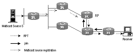
Figure 7-1 RPT schematic diagram
II. Multicast source registration
When multicast source S sends a multicast packet to the multicast group G, the PIM-SM multicast router directly connected to S will encapsulate the received packet into a registration packet and send it to the corresponding RP in unicast form. If there are multiple PIM-SM multicast routers on a network segment, the Designated Router (DR) will be responsible for sending the multicast packet.
7.1.3 Preparations before Configuring PIM-SM
I. Configuring candidate RPs
In a PIM-SM network, multiple RPs (candidate-RPs) can be configured. Each Candidate-RP (C-RP) is responsible for forwarding multicast packets with the destination addresses in a certain range. Configuring multiple C-RPs is to implement load balancing of the RP. These C-RPs are equal. All multicast routers calculate the RPs corresponding to multicast groups according to the same algorithm after receiving the C-RP messages that the BSR advertises.
![]() Caution:
Caution:
One RP can serve multiple multicast groups or all multicast groups. Each multicast group can correspond to one unique RP at a time rather than multiple RPs.
II. Configuring BSRs
The BSR is the management core in a PIM-SM network. Candidate-RPs send announcement to the BSR, which is responsible for collecting and advertising the information about all candidate-RPs.
![]() Caution:
Caution:
There can be only one BSR in a network but you can configure multiple candidate-BSRs. In this case, once a BSR fails, you can switch over to another BSR. A BSR is elected among the C-BSRs automatically. The C-BSR with the highest priority is elected as the BSR. If the priority is the same, the C-BSR with the largest IP address is elected as the BSR.
III. Configuring static RP
The router that serves as the RP is the core router of multicast routes. If the dynamic RP elected by BSR mechanism is invalid for some reason, the static RP can be configured to specify RP. As the backup of dynamic RP, static RP improves network robustness and enhances the operation and management capability of multicast network.
7.2 PIM-SM Configuration
1) PIM-SM basic configuration includes:
l Enabling Multicast
l Enabling PIM-SM
l Entering the PIM view
l Configuring candidate-BSRs
l Configuring candidate-RPs
l Configuring static RP
2) PIM-SM advanced configuration includes:
l Configuring the PIM-SM domain boundary
l Configuring the sending interval for the Hello packets of the interface
l Configuring the filtering of multicast source/group
l Configuring the filtering of PIM neighbor
l Configuring the maximum number of PIM neighbor on an interface
l Configuring RP to filter the register messages
l Limiting the range of legal BSR
l Limiting the range of legal C-RP
l Clearing multicast route entries from PIM routing table
l Clearing PIM neighbor
![]() Caution:
Caution:
At least one router in an entire PIM-SM domain should be configured with C-RPs and C-BSRs.
7.2.1 Enabling Multicast
Refer to 4.2.1 Enabling Multicast Routing.
7.2.2 Enabling PIM-SM
This configuration can be effective only after multicast is enabled.
Perform the following configuration in VLAN interface view.
|
Operation |
Command |
|
Enable PIM-SM on an interface |
pim sm |
|
Disable PIM-SM on an interface |
undo pim sm |
Repeat this configuration to enable PIM-SM on other interfaces. Only one multicast routing protocol can be enabled on an interface at a time.
Once enabled PIM-SM on an interface, PIM-DM cannot be enabled on the same interface and vice versa.
7.2.3 Entering the PIM View
Refer to 6.2.4 Entering the PIM View.
7.2.4 Configuring the Time Intervals for Ports to Send Hello Packets
In general, PIM-SM broadcasts Hello packets on the PIM-SM-enabled port periodically to detect PIM neighbors and determine the designated router (DR).
For details, refer to 6.2.3 Configuring the Time Intervals for Ports to Send Hello Packets.
7.2.5 Configuring Candidate-BSRs
In a PIM domain, one or more candidate BSRs should be configured. A BSR (Bootstrap Router) is elected among candidate BSRs. The BSR takes charge of collecting and advertising RP information.
The automatic election among candidate BSRs is described as follows:
One interface which has started PIM-SM must be specified when configuring the router as the candidate BSR.
At first, each candidate BSR considers itself as the BSR of the PIM-SM domain, and sends Bootstrap message by taking the IP address of the interface as the BSR address.
When receiving Bootstrap messages from other routers, the candidate BSR will compare the BSR address of the newly received Bootstrap message with that of itself. Comparison standards include priority and IP address. The bigger IP address is considered better when the priority is the same. If the priority of the former is higher, the candidate BSR will replace its BSR address and stop regarding itself as the BSR. Otherwise, the candidate BSR will keep its BSR address and continue to regard itself as the BSR.
Perform the following configuration in PIM view.
Table 7-2 Configuring candidate-BSRs
|
Operation |
Command |
|
Configure a candidate-BSR |
c-bsr Vlan-interface Vlan-interface-number hash-mask-len [ priority ] |
|
Remove the candidate-BSR configured |
undo c-bsr |
Candidate-BSRs should be configured on the routers in the network backbone. By default, no BSR is set. The default priority is 0.
![]() Caution:
Caution:
One router can only be configured with one candidate-BSR. When a candidate-BSR is configured on another interface, it will replace the previous configuration.
7.2.6 Configuring Candidate-RPs
In PIM-SM, the shared tree built by multicast routing data is rooted at the RP. There is a mapping from a multicast group to an RP. A multicast group can be mapped to only one RP. Different multicast groups can be mapped to the same RP or different RPs.
Perform the following configuration in PIM view.
Table 7-3 Configuring candidate-RPs
|
Operation |
Command |
|
Configure a candidate-RP |
c-rp interface-type interface-number [ group-policy acl-number | priority priority-value ]* |
|
Remove the candidate-RP configured |
undo c-rp { interface-type interface-number | all } |
When configuring RP, if the range of the served multicast group is not specified, the RP will serve all multicast groups. Otherwise, the range of the served multicast group is the multicast group in the specified range. It is suggested to configure Candidate RP on the backbone router.
7.2.7 Configuring Static RP
To enhance network robustness, static RP serves as the backup of dynamic RP
Table 7-4 Configuring static RP
|
Operation |
Command |
Description |
|
Enter system view |
system-view |
- |
|
Enter PIM view |
pim |
Required |
|
Configure static RP |
static-rp rp-address [ acl-number ] |
Required |
![]() Caution:
Caution:
l When the RP elected by BSR mechanism is effective, static RP does not work.
l All routers in the PIM domain must be configured with this command simultaneously, with the same RP address specified.
l The system supports up to ten different static RP addresses. When more than ten static RP addresses are configured, the system will give this prompt information: “Cannot config static-rp, exceeded static-rp limit 10”.
7.2.8 Configuring the PIM-SM Domain Border
After the PIM-SM domain border is configured, bootstrap messages can not cross the border in any direction. In this way, the PIM-SM domain can be split.
Perform the following configuration in VLAN interface view.
Table 7-5 Configuring the PIM-SM domain border
|
Operation |
Command |
|
Set the PIM-SM domain border |
pim bsr-boundary |
|
Remove the PIM-SM domain border configured |
undo pim bsr-boundary |
By default, no domain border is set.
After this configuration is performed, a bootstrap message can not cross the border but other PIM packets can. This configuration can effectively divide a network into domains using different BSRs.
7.2.9 Configuring the filtering of multicast source/group
Refer to 6.2.5 Configuring the Filtering of Multicast Source/Group.
7.2.10 Configuring the filtering of PIM neighbor
Refer to 6.2.6 Configuring the Filtering of PIM Neighbor.
Refer to 6.2.7 Configuring the Maximum Number of PIM Neighbor on an Interface.
7.2.11 Configuring RP to Filter the Register Messages Sent by DR
In the PIM-SM network, the register message filtering mechanism can control which sources to send messages to which groups on the RP, i.e., RP can filter the register messages sent by DR to accept specified messages only.
Perform the following configuration in PIM view.
Table 7-6 Configuring RP to filter the register messages sent by DR
|
Operation |
Command |
|
Configure RP to filter the register messages sent by DR |
register-policy acl-number |
|
Cancel the configured filter of messages |
undo register-policy |
If an entry of a source group is denied by the ACL, or the ACL does not define operation to it, or there is no ACL defined, the RP will send RegisterStop messages to the DR to prevent the register process of the multicast data stream.
![]() Caution:
Caution:
Only the register messages matching the ACL permit clause can be accepted by the RP. Specifying an undefined ACL will make the RP deny all register messages.
7.2.12 Limiting the range of legal BSR
To prevent the legal BSR from being replaced maliciously in the network, you can limit the range of legal BSR. Other BSR messages beyond the range are not received by the router and thus ensure the BSR security.
Perform the following configuration in PIM view.
Table 7-7 Limiting the range of legal BSR
|
Operation |
Command |
|
Set the limit legal BSR range |
bsr-policy acl-number |
|
Restore to the default setting |
undo bsr-policy |
For detailed information of bsr-policy, refer to the H3C S9500 Series Routing Switches Command Manual.
7.2.13 Limiting the range of legal C-RP
To avoid C-RP spoofing, you can limit the range of legal C-RP and limit the groups that each C-RP servers.
Perform the following configuration in PIM view.
Table 7-8 Limiting the range of legal C-RP
|
Operation |
Command |
|
Set the limit legal C-RP range |
crp-policy acl-number |
|
Restore to the default setting |
undo crp-policy |
For detailed information of crp-policy, refer to the H3C S9500 Series Routing Switches Command Manual
7.2.14 Clearing multicast route entries from PIM routing table
Refer to 6.2.8 Clearing PIM Routing Table.
7.2.15 Clearing PIM Neighbors
Refer to 6.2.9 Clearing PIM Neighbors.
7.3 Displaying and Debugging PIM-SM
After the above configuration, execute display command in any view to display the running of PIM-SM configuration, and to verify the effect of the configuration.
Execute debugging command in user view for the debugging of PIM-SM.
Table 7-9 Displaying and debugging PIM-SM
|
Operation |
Command |
|
Display the BSR information |
display pim bsr-info |
|
Display the RP information |
display pim rp-info [ group-address ] |
|
Enable the PIM-SM debugging |
debugging pim sm { all | mbr { alert | fresh } | verbose | mrt | msdp | timer { assert | bsr | crpadv | jp | jpdelay | mrt | probe | spt } | warning | { recv | send } { assert | bootstrap | crpadv | jp | reg | regstop } |
|
Disable the PIM-SM debugging |
undo debugging pim sm { all | mbr { alert | fresh } | verbose | mrt | msdp | timer { assert | bsr | crpadv | jp | jpdelay | mrt | probe | spt } | warning | { recv | send } { assert | bootstrap | crpadv | jp | reg | regstop } |
7.4 PIM-SM Configuration Example
I. Networking requirements
In actual network, we assume that the switches can intercommunicate and the IP address of each VLAN interface has been configured.
l LSA is connected to LSB through VLAN-interface10, connected to HostA through VLAN-interface11 and connected to LSC through VLAN-interface12.
l LSB is connected to LSA through VLAN-interface10, connected to LSC through VLAN-interface11 and connected to LSD through VLAN-interface12.
l LSC is connected to HostB through VLAN-interface10, connected to LSB through VLAN-interface11 and connected to LSA through VLAN-interface12.
Suppose that Host A is the receiver of the multicast group at 225.1.1.1. Host B begins transmitting data destined to 225.1.1.1. LSA receives the multicast data from Host B via LSB.
II. Networking diagram
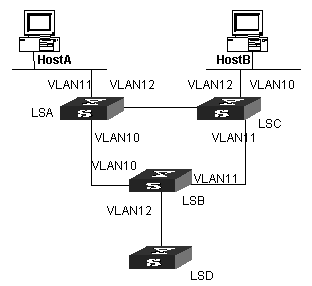
Figure 7-2 PIM-SM configuration networking
III. Configuration procedure
1) Configure LSA
# Enable PIM-SM.
<H3C>system-view
System View: return to User View with Ctrl+Z.
[H3C] multicast routing-enable
[H3C] vlan 10
[H3C-vlan10] port ethernet 2/1/2 to ethernet 2/1/3
[H3C-vlan10] quit
[H3C] interface vlan-interface 10
[H3C-vlan-interface10] igmp enable
[H3C-vlan-interface10] pim sm
[H3C-vlan-interface10] quit
[H3C] vlan 11
[H3C-vlan11] port ethernet 2/1/4 to ethernet 2/1/5
[H3C-vlan11] quit
[H3C] interface vlan-interface 11
[H3C-vlan-interface11] igmp enable
[H3C-vlan-interface11] pim sm
[H3C-vlan-interface11] quit
[H3C] vlan 12
[H3C-vlan12] port ethernet 2/1/6 to ethernet 2/1/7
[H3C-vlan12] quit
[H3C] interface vlan-interface 12
[H3C-vlan-interface12] igmp enable
[H3C-vlan-interface12] pim sm
[H3C-vlan-interface12] quit
2) Configure LSB
# Enable PIM-SM.
[H3C] multicast routing-enable
[H3C] vlan 10
[H3C-vlan10] port ethernet 2/1/2 to ethernet 2/1/3
[H3C-vlan10] quit
[H3C] interface vlan-interface 10
[H3C-vlan-interface10] igmp enable
[H3C-vlan-interface10] pim sm
[H3C-vlan-interface10] quit
[H3C] vlan 11
[H3C-vlan11] port ethernet 2/1/4 to ethernet 2/1/5
[H3C-vlan11] quit
[H3C] interface vlan-interface 11
[H3C-vlan-interface11] igmp enable
[H3C-vlan-interface11] pim sm
[H3C-vlan-interface11] quit
[H3C] vlan 12
[H3C-vlan12] port ethernet 2/1/6 to ethernet 2/1/7
[H3C-vlan12] quit
[H3C] interface vlan-interface 12
[H3C-vlan-interface12] igmp enable
[H3C-vlan-interface12] pim sm
[H3C-vlan-interface12] quit
# Configure the C-BSR.
[H3C] pim
[H3C-pim] c-bsr vlan-interface 10 30 2
# Configure the C-RP.
[H3C] acl number 2000
[H3C-acl-basic-2000] rule permit source 225.0.0.0 0.255.255.255
[H3C] pim
[H3C-pim] c-rp vlan-interface 10 group-policy 2000
# Configure PIM domain border.
[H3C] interface vlan-interface 12
[H3C-vlan-interface12] pim bsr-boundary
After VLAN-interface 12 is configured as domain border, the LSD will be excluded from the local PIM domain and cannot receive the BSR information transmitted from LSB any more.
3) Configure LSC.
# Enable PIM-SM.
[H3C] multicast routing-enable
[H3C] vlan 10
[H3C-vlan10] port ethernet 2/1/2 to ethernet 2/1/3
[H3C-vlan10] quit
[H3C] interface vlan-interface 10
[H3C-vlan-interface10] igmp enable
[H3C-vlan-interface10] pim sm
[H3C-vlan-interface10] quit
[H3C] vlan 11
[H3C-vlan11] port ethernet 2/1/4 to ethernet 2/1/5
[H3C-vlan11] quit
[H3C] interface vlan-interface 11
[H3C-vlan-interface11] igmp enable
[H3C-vlan-interface11] pim sm
[H3C-vlan-interface11] quit
[H3C] vlan 12
[H3C-vlan12] port ethernet 2/1/6 to ethernet 2/1/7
[H3C-vlan12] quit
[H3C] interface vlan-interface 12
[H3C-vlan-interface12] igmp enable
[H3C-vlan-interface12] pim sm
[H3C-vlan-interface12] quit
& Note:
You should enable PIM-SM on all equal-cost routes if there are any.
Chapter 8 MSDP Configuration
8.1 MSDP Overview
8.1.1 Introduction
No ISP would like to forward multicast traffic depending on the RP of competitors, though it has to obtain information from the source and distribute it among its members, regardless of the location of the source RP. MSDP is proposed to solve this problem. Multicast source discovery protocol (MSDP) describes interconnection mechanism of multiple PIM-SM domains. It is used is to discover multicast source information in other PIM-SM domains. MSDP allows the RPs of different domains to share the multicast source information, but all these domains must use PIM-SM as their intro-domain multicast routing protocol.
A RP configured with MSDP peer notifies all of its MSDP peers of the active multicast source message in its domain via SA (Source Active) message. In this way, multicast source information in a PIM-SM domain is transmitted to another PIM-SM domain.
MSDP peer relationship can be established between RPs in different domains or in a same domain, between a RP and a common router, or between common routers. The connection between MSDP peers is TCP connection.
MSDP makes a PIM-SM domain independent of the RP in another PIM-SM domain. After getting multicast source information in that domain, the receiver here can join directly to the SPT of the multicast source in that domain.
Another application of MSDP is Anycast RP. In a domain, configure a certain interface (usually Loopback interface) on different routers with a same IP address; designate these interfaces as C-RPs; and create MSDP peer relationship among them. After the unicast route convergence, the multicast source can select the nearest RP for registration, and the receiver can also select the nearest RP to add into its RPT. The RPs exchange individual registration source information via MSDP peers. Therefore, every RP knows all multicast sources of the entire domain; and every receiver on each RP can receive multicast data from all the multicast sources in the entire domain.
By initiating registration and RPT joining to the nearest RP, MSDP implements RP load sharing. Once an RP turns invalid, its original registered source and receivers will select another nearest RP, implementing redundant RP backup.
In addition, MSDP only accepts the SA messages from the correct paths and excludes redundant SA messages through RPF check mechanism, and prevents the flooding of SA messages among MSDP peers by configuring Mesh Group.
8.1.2 Working Principle
I. Identifying multicast source and receiving multicast data
As shown in Figure 8-1, the RPs of PIM-SM domains 1, 2 and 3 establish peer relationship between them. Domain 3 contains a group member.
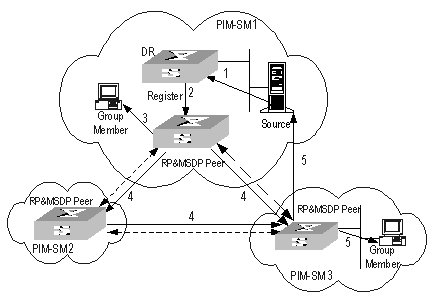
Figure 8-1 MSDP working principles (I)
When the multicast source in domain 1 sends data to the multicast group, the working process of the member in domain 3, from discovering the multicast source to receiving data from the source, includes the following:
1) The multicast source in PIM-SM domain 1 begins to send datagram.
2) The DR connected to the multicast source encapsulates the datagram into a Register packet and forward to the RP in domain 1.
3) The RP in domain 1 decapsulates the packet and forwards it along the RPT to all the members within the domain. The domain members can choose to take the path along SPT.
4) The RP in domain 1 generates an SA (Source Active) message for the MSDP peers (the RPs in PIM-SM domain 2 and domain 3). The SA message contains multicast source IP address, multicast group address and the address of the RP that generates the message. Besides, the RP in domain 1 encapsulates the first received multicast data into this SA message.
5) If there is any group member in the domain of an MSDP peer (in the figure, it is PIM-SM domain 3), the RP in this domain sends the multicast data encapsulated in the SA message to group members along the RPT and the join message to multicast source.
6) After the reverse forwarding path is created, the multicast source data is sent directly to the RP in domain 3, which then RP forwards the data along the RPT. In this case, the last hop router connected with the group member in domain 3 can choose whether to switch to SPT.
II. Message forwarding and RPF check between MSDP peers
As shown in Figure 8-2 MSDP working principles (II), Switch A, Switch B, Switch C, Switch D, Switch E and Switch F belong to domain 1, domain 2 and domain 3 respectively. MSDP peer relationship is established between them, indicated with bi-directional arrows in the figure. Among them, Mesh Group is created among Switch B, Switch C and Switch D.
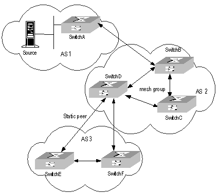
Figure 8-2 MSDP working principles (II)
The SA message forwarding and RPF check among these MSDP peers are illustrated as follows:
1) If the SA message is from a MSDP peer that is the RP of the multicast source as from Switch A to Switch B, it is received and forwarded to other peers.
2) If the SA message is from a MSDP peer that has only one peer as from Switch B to Switch A, it is received.
3) If the SA message is from a static RPF peer as from Switch D to Switch E, it is received and forwarded to other peers.
4) If the SA message is from a MSDP peer in Mesh Group as from Switch B to Switch D, it is received and forwarded to the peers outside the Mesh Group.
5) If the SA message is sent from a MSDP peer in a same domain, and the peer is the next hop along the optimal path to the RP in the domain of source, as in the case when the message is from Switch E to Switch F, it is received and forwarded to other peers.
6) If the SA message is sent from a MSDP peer in a different domain which is the next autonomous domain along the optimal path to the RP in the domain of source, as from Switch D to Switch F, it is received and forwarded to other peers.
7) For other SA messages, they are neither received nor forwarded.
III. Precautions for configuration
The router operating MSDP must also run BGP or MBGP. It is recommended to use the same IP address of the MSDP peer with that of the BGP peer or MBGP peer. If neither BGP nor MBGP is in operation, a static RPF peer should be configured.
8.2 MSDP Configuration
1) Basic configuration tasks of MSDP include
l Enable MSDP
l Configure MSDP peers
2) Advanced configuration tasks of MSDP include
l Configure static RPF peers
l Configure Originating RP
l Configure SA caching state
l Configure the maximum number of SA caching
l Request the source information of MSDP peers
l Control the source information created
l Control the source information forwarded
l Control the received source information
l Configure MSDP full connection group
l Configure the MSDP connection retry period
l Disable MSDP peers
l Clear MSDP connection, statistics and SA cache
8.2.1 Enabling MSDP
To configure MSDP, you must enable MSDP first.
Please perform the following configurations in system view.
|
Operation |
Command |
|
Enable MSDP and enter MSDP view |
msdp |
|
Clear all MSDP configurations |
undo msdp |
8.2.2 Configuring MSDP Peers
To run MSDP, you need to configure MSDP peers locally.
Please perform the following configurations in MSDP view.
Table 8-2 Configuring MSDP peers
|
Operation |
Command |
|
Configure MSDP peers |
peer peer-address connect-interface interface-type interface-number |
|
Remove MSDP peer configuration |
undo peer peer-address |
|
Add description to a MSDP peer |
peer peer-address description text |
|
Remove the description |
undo peer peer-address description text |
The command to add description is optional.
If the local router is also in BGP Peer relation with a MSDP peer, the MSDP peer and the BGP peer should use the same IP address.
Not any two routers between which MSDP peer relationship has been established must run BGP or MBGP, so long as they have a BGP or MBGP route between them. If no BGP of MBGP route exists between them, then you must configure static RPF peers.
8.2.3 Configuring Static RPF Peers
Please perform the following configurations in MSDP view.
Table 8-3 Configuring static RPF peers
|
Operation |
Command |
|
Configure static RPF peers |
static-rpf-peer peer-address [ rp-policy ip-prefix-name] |
|
Remove static RPF peer configuration |
undo static-rpf-peer peer-address |
By default, no static RPF peer is configured.
& Note:
l The peer command must be configured before the configuration of static-rpf-peer command.
l If only one MSDP peer is configured via the peer command, the MSDP peer will be regarded as the static RPF peer.
To configure multiple static RPF peers at the same time, take any of the two methods:
l Using rp-policy parameters universally: Multiple static RPF peers take effect at the same time and SA messages are filtered by the RP addresses contained according to the configured prefix list. If multiple static RPF peers using the same rp-policy parameter are configured, any peer that receives an SA message will forward it to the other peers.
l Not using the rp-policy parameter universally: According to the configuration sequence, only the first static RPF peer whose connection state is UP is activated. All SA messages from the peer will be received and those from other static RPF peers will be discarded. Once the activated static RPF peer turns invalid (possibly out of configuration removed or connection interrupted), the following first static RPF peer with UP connection state according to the configuration sequence will assume its role.
8.2.4 Configuring Originating RP
During the creation of SA message, an MSDP peer can be configured to use the IP address of a specified interface as the RP address in its SA message.
Please perform the following configurations in MSDP view.
Table 8-4 Configuring Originating RP
|
Operation |
Command |
|
Configure an MSDP peer to use the IP address of a specified interface as the RP address of its SA message |
originating-rp interface-type interface-number |
|
Remove the above operation |
undo originating-rp |
By default, the RP address in SA message is the one configured by PIM.
8.2.5 Configuring SA Caching State
When SA messages are cached on a router, the new join-in groups can directly access all the active sources and join to the corresponding source tree, instead of waiting for the arrival of the next SA message.
Please perform the following configurations in MSDP view.
Table 8-5 Configuring SA caching state
|
Operation |
Command |
|
Configure SA caching state |
cache-sa-enable |
|
Disable SA caching state |
undo cache-sa-enable |
By default, the router caches the SA state, or rather the (S, G) entry when receiving an SA message.
Some memory is consumed as the join delay of groups is shortened by this configuration.
8.2.6 Configuring the Maximum Number of SA caching
To prevent DoS (Deny of Service) attacks, you can set the maximum number of SAs cached on the router.
Perform the following configuration in MSDP view.
Table 8-6 Configuring the maximum number of SA caching
|
Operation |
Command |
|
Configuring the maximum number of SA caching |
peer peer-address sa-cache-maximum sa-limit |
|
Restore the default configuration |
undo peer peer-address sa-cache-maximum |
By default, the maximum number of SA caching is 2048.
8.2.7 Requesting Source Information of MSDP Peers
When a new group joins, the router will send a SA request message to the specified MSDP peer, and the MSDP peer will respond with the SA messages it caches. If the MSDP peer does not enable the SA caching, the configuration is invalid.
Please perform the following configurations in MSDP view.
Table 8-7 Requesting source information of MSDP peers
|
Operation |
Command |
|
Configure the router to send SA request message to the specified MSDP peer when receiving the join message of a group |
peer peer-address request-sa-enable |
|
Restore the default configuration |
undo peer peer-address request-sa-enable |
The SA request message sent by a local RP will get the immediate response about all active sources.
By default, the router does not send SA request message to its MSDP peer when receiving the join message of a group. Instead, it waits for the arrival of SA message of the next period.
8.2.8 Controlling the Source Information Created
I. Filtering the multicast routing entries imported
RP filters the registered sources to control the information of the active sources advertised in SA message. MSDP peers can be configured to only advertise the qualified (S, G) entries in the multicast routing table when creating SA messages, that is, to control the (S,G) entries imported from the multicast routing table to the domain.
Please perform the following configurations in MSDP view.
Table 8-8 Filtering the multicast routing entries imported
|
Operation |
Command |
|
Advertise only the (S, G) entries permitted by the ACL |
import-source [ acl acl-number ] |
|
Remove the above configuration |
undo import-source |
By default, only intra-domain sources are advertised in SA messages.
If the import-source command without acl parameter is executed, no source is advertised in SA messages.
II. Filtering SA request messages
Please perform the following configurations in MSDP view.
Table 8-9 Filtering SA request messages
|
Operation |
Command |
|
Filter all the SA request messages from a specified MSDP peer |
peer peer-address sa-request-policy |
|
Filter the SA request messages of the groups of a specified MSDP peer permitted by the basic ACL from |
peer peer-address sa-request-policy acl acl-number |
|
Remove the configuration of filtering SA request messages |
undo peer peer-address sa-request-policy |
By default, only the routers which caches SA messages can respond to SA request messages. Routers receive all SA request messages from its MSDP peers.
Multicast group addresses are described in ACL. If no ACL is specified, all SA request messages sent by the corresponding MSDP peer will be ignored. If an ACL is specified, only SA request messages of the groups permitted by the ACL will be processed.
8.2.9 Controlling the Source Information Forwarded
Controlling of source information also includes that of forwarding and receiving source information besides that of creating source information. The outbound filter or time to live (TTL) threshold of SA messages can be used to control the SA message forwarding. By default, all SA messages are forwarded to other MSDP peers.
I. Using MSDP outbound filter
MSDP outbound filter of are functional in:
l Filtering off all the (S, G) entries
l Forwarding only the SA messages permitted by the advanced ACL
Please perform the following configurations in MSDP view.
Table 8-10 Using MSDP outbound filter to control the source information forwarded
|
Operation |
Command |
|
Filter off all the SA messages to a specified MSDP peer |
peer peer-address sa-policy export |
|
Forward the SA messages permitted by the advanced ACL to a specified MSDP peer |
peer peer-address sa-policy export acl acl-number |
|
Remove the filtering over the source information forwarded |
undo peer peer-address sa-policy export |
II. Using TTL to filter SA messages with encapsulated data
An SA message with encapsulated data can reach the specified MSDP peer only when the TTL in its IP header is no less than the threshold. Therefore, the forwarding of SA messages with encapsulated data can be controlled by configuring the TTL threshold.
For example, you can set the TTL threshold for intra-domain multicast traffic as 10 if you wish to restrict SA messages with TTL less than or equal to 10 carrying encapsulated data from being propagated. If you set the TTL threshold greater than 10, then they can be propagated to outside.
Please perform the following configurations in MSDP view.
Table 8-11 Using TTL to filter SA messages with encapsulated data
|
Operation |
Command |
|
Filter off the multicast data encapsulated in the first SA message aiming at a specified MSDP peer |
peer peer-address minimum-ttl ttl |
|
Remove the TTL threshold configuration |
undo peer peer-address minimum-ttl |
The default value of TTL threshold is 0.
8.2.10 Controlling the Received Source Information
Please perform the following configurations in MSDP view.
Table 8-12 Controlling the received source information
|
Operation |
Command |
|
Filter off the SA messages from a specified MSDP peer |
peer peer-address sa-policy import |
|
Receive the SA messages permitted by the advanced ACL from a specified MSDP peer |
peer peer-address sa-policy import acl acl-number |
|
Remove the filtering rule over received source information |
undo peer peer-address sa-policy import |
Similar to MSDP outbound filter in function, MSDP inbound filter controls the received SA messages. By default, the SA messages from all peers are accepted.
8.2.11 Configuring MSDP Mesh Group
Mesh Group is useful when full connection among MSDP peers is required but SA message flooding shall be prevented.
In a Mesh group, the SA messages from outside the group are forwarded to other members in the group, but the SA messages from peers inside the group will not be performed with Peer-RPF check or forwarded in the group. In this case, the overflow of SA messages is avoided and Peer-RPF is simplified, as BGP or MBGP is not required between MSDP peers.
Please perform the following configurations in MSDP view.
Table 8-13 Configuring MSDP full connection group
|
Operation |
Command |
|
Configure an MSDP peer to be a member of an MSDP Mesh Group |
peer peer-address mesh-group name |
|
Delete that member from the Group |
undo peer peer-address mesh-group name |
If an MSDP peer is configured into different mesh groups, only the last configuration is valid.
8.2.12 Configuring the MSDP Connection Retry Period
Perform the following configurations in MSDP view.
Table 8-14 Configuring the MSDP connection retry period
|
Operation |
Command |
|
Configuring the MSDP connection retry period |
timer retry seconds |
|
Restore the default value of MSDP connection retry interval |
undo timer retry |
By default, MSDP connection is retried at the interval of 30 seconds.
8.2.13 Shutting MSDP Peers Down
The session between MSDP peers can be cut off and re-activated as needed.
If a session between MSDP peers is cut off, the TCP connection will terminate with no retry effort, but the configuration information will be reserved.
Please perform the following configurations in MSDP view.
Table 8-15 Shutting MSDP peers down
|
Operation |
Command |
|
Shut a specified MSDP peer down |
shutdown peer-address |
|
Turn the MSDP peer up |
undo shutdown peer-address |
By default, MSDP peer is enabled.
8.2.14 Clearing MSDP Connections, Statistics and SA Caching Configuration
Perform the following configurations in user view.
Table 8-16 Clearing MSDP connections, statistics and SA caching configuration
|
Operation |
Command |
|
Clear a specified TCP connection and reset the counters of all MSDP information |
reset msdp peer peer-address |
|
Clear MSDP peer statistics |
reset msdp statistics [ peer-address ] |
|
Clear cached SA entries of MSDP |
reset msdp sa-cache [ group-address ] |
8.3 Displaying and Debugging MSDP
I. Displaying and Debugging MSDP
After the above configuration, execute display commands in any view to display the running information of MSDP and to verify the effect of the configuration.
Execute the debugging command in user view for the debugging of MSDP.
Table 8-17 Displaying and debugging MSDP configuration
|
Operation |
Command |
|
Display the numbers of sources and groups of SA messages from a specified autonomous domain |
display msdp sa-count [ as-number ] |
|
Display the details of a MSDP peer |
display msdp peer-status [ peer-address ] |
|
Display the (S,G) state learnt from MSDP peer |
display msdp sa-cache [ group-address | source-address | autonomous-system-number ] * |
|
Display MSDP peer state |
display msdp brief |
|
Enable MSDP debugging |
debugging msdp { all | connect | event | packet | source-active } |
![]() Caution:
Caution:
The display msdp sa-count command give output only after the cache-sa-enable command is executed.
II. Tracing the Transmission Path of SA Messages on the Network
The msdp-tracert command can be used in any view to trace the network path of multicast data from multicast source to destination receiver and locate faults.
Table 8-18 Tracing the transmission path of SA messages on the network
|
Operation |
Command |
|
Trace the transmission path of SA messages on the network |
msdp-tracert { source-address } { group-address } { rp-address } [ max-hops max-hops ] [ next-hop-info ] [ sa-info ] [ peer-info ] [ skip-hops skip-hops ] |
Locating information loss and reducing configuration faults can be realized by tracing the network path of the specified (S, G, RP) entries. After the transmission path of SA messages is determined, the overflow of SA messages can be avoided by the correct configuration.
8.4 MSDP Configuration Examples
8.4.1 Configuring Static RPF Peers
I. Networking requirements
In the following networking environment shown in Figure 8-3, four H3C S9500 Series routing Switches all are in the PIM-SM domains with no BGP or MBGP running among them.
To enable Switch D to receive the specified source information from PIM-SM domains 1, 2 and 3, you can configure static RPF peers with the parameter rp-policy.
After the configuration is complete, Switch D will only receive SA messages permitted by the corresponding filtering policy from its static RPF peers.
II. Networking diagram
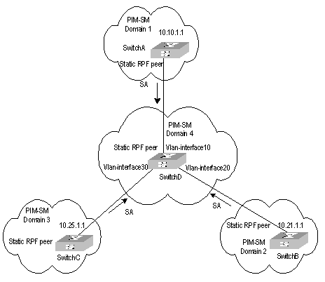
Figure 8-3 Configuring static RPF peers
III. Configuration procedure
The following configuration is made on Switch D.
# Configure Switch A to be a static RPF peer of Switch D.
<SwitchD> system-view
System View: return to User View with Ctrl+Z.
[SwitchD] ip ip-prefix list-a permit 10.10.0.0 16
[SwitchD] msdp
[SwitchD-msdp] peer 10.10.1.1 connect-interface Vlan-interface 10
[SwitchD-msdp] static-rpf-peer 10.10.1.1 rp-policy list-a
[SwitchD-msdp] quit
# Configure Switch B to be a static RPF peer of Switch D.
[SwitchD] ip ip-prefix list-b permit 10.21.0.0 16
[SwitchD] msdp
[SwitchD-msdp] peer 10.21.1.1 connect-interface Vlan-interface 20
[SwitchD-msdp] static-rpf-peer 10.21.1.1 rp-policy list-b
[SwitchD-msdp] quit
# Configure Switch C to be a static RPF peer of Switch D.
[SwitchD] ip ip-prefix list-c permit 10.25.0.0 16
[SwitchD] msdp
[SwitchD-msdp] peer 10.25.1.1 connect-interface Vlan-interface30
[SwitchD-msdp] static-rpf-peer 10.25.1.1 rp-policy list-c
8.4.2 Configuring Anycast RP
I. Networking requirements
To configure Anycast RP in the PIM-SM domain, establish MSDP peer relationship between Switch A and Switch B; use the address of loopback0 on Switch A and Switch B to send SA messages outside; set Loopback10 interface on Switch A and Switch B as BSR/RP and configure the Anycast RP address. In this way, when a unicast group member joins, the switch directly connected to the host can originate a join message to the nearest RP in the topology.
& Note:
This example focuses on the configuration of Switch A and Switch B. Configuration performed on Switch E, Switch D and Switch C is omitted as it mainly concerns enabling multicast and enabling PIM-SM on the interfaces.
II. Networking diagram
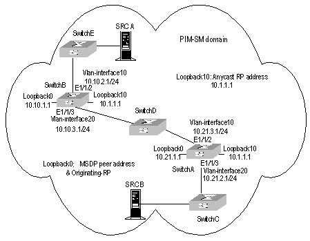
Figure 8-4 Networking diagram for Anycast RP configuration
III. Configuration procedure
1) Configure SwitchB:
# Configure VLAN
<SwitchB> system-view
System View: return to User View with Ctrl+Z.
[SwitchB] vlan 10
[SwitchB-vlan10] port ethernet1/1/2
[SwitchB-vlan10] quit
[SwitchB] vlan 20
[SwitchB-vlan20] port ethernet1/1/3
[SwitchB-vlan20] quit
# Enable multicast.
[SwitchB] multicast routing-enable
# Configure the IP address of interface loopback0.
[SwitchB] interface loopback0
[SwitchB-LoopBack0] ip address 10.10.1.1 255.255.255.255
[SwitchB-LoopBack0] quit
# Configure the IP address of interface loopback10 and enable IGMP and PIM-SM.
[SwitchB] interface loopback10
[SwitchB-LoopBack10] ip address 10.1.1.1 255.255.255.255
[SwitchB-LoopBack10] igmp enable
[SwitchB-LoopBack10] pim sm
[SwitchB-LoopBack10] quit
# Configure the IP address of Vlan-interface10 and enable IGMP and PIM-SM.
[SwitchB] interface Vlan-interface10
[SwitchB-Vlan-interface10] ip address 10.10.2.1 255.255.255.0
[SwitchB-Vlan-interface10] igmp enable
[SwitchB-Vlan-interface10] pim sm
[SwitchB-Vlan-interface10] undo shutdown
[SwitchB-Vlan-interface10] quit
# Configure the IP address of Vlan-interface20 and enable IGMP and PIM-SM.
[SwitchB] interface Vlan-interface20
[SwitchB-Vlan-interface20] ip address 10.10.3.1 255.255.255.0
[SwitchB-Vlan-interface20] igmp enable
[SwitchB-Vlan-interface20] pim sm
[SwitchB-Vlan-interface20] undo shutdown
[SwitchB-Vlan-interface20] quit
# Configure OSPF
[SwitchB] ospf
[SwitchB-ospf-1] area 0
[SwitchB-ospf-1-area-0.0.0.0] network 10.10.2.0 0.255.255.255
[SwitchB-ospf-1-area-0.0.0.0] network 10.10.3.0 0.255.255.255
[SwitchB-ospf-1-area-0.0.0.0] network 10.1.1.1 0.0.0.0
[SwitchB-ospf-1-area-0.0.0.0] network 10.10.1.1 0.0.0.0
[SwitchB-ospf-1-area-0.0.0.0] quit
[SwitchB-ospf-1] quit
# Configure Switch A as its MSDP peer.
[SwitchB] msdp
[SwitchB-msdp] peer 10.21.1.1 connect-interface loopback 0
# Configure Originating RP.
[SwitchB-msdp] originating-rp loopback0
[SwitchB-msdp] quit
# Configure C-RP and BSR.
[SwitchB] pim
[SwitchB-pim] c-rp loopback 10
[SwitchB-pim] c-bsr loopback 10 30
2) Configure Switch A:
# Configure VLAN
<SwitchA> system-view
System View: return to User View with Ctrl+Z.
[SwitchA] vlan 10
[SwitchA-vlan10] port ethernet1/1/2
[SwitchA-vlan10] quit
[SwitchA] vlan 20
[SwitchA-vlan20] port ethernet1/1/3
[SwitchA-vlan20] quit
# Enable multicast.
[SwitchA] multicast routing-enable
# Configure the IP address of interface loopback0.
[SwitchA] interface loopback0
[SwitchA-LoopBack0] ip address 10.21.1.1 255.255.255.255
[SwitchA-LoopBack0] quit
# Configure the IP address of interface loopback10 and enable IGMP and PIM-SM.
[SwitchA] interface loopback10
[SwitchA-LoopBack10] ip address 10.1.1.1 255.255.255.255
[SwitchA-LoopBack10] igmp enable
[SwitchA-LoopBack10] pim sm
[SwitchA-LoopBack10] quit
# Configure the IP address of interface Vlan-interface20 and enable IGMP and PIM-SM.
[SwitchA] interface Vlan-interface20
[SwitchA-Vlan-interface20] ip address 10.21.2.1 255.255.255.0
[SwitchA-Vlan-interface20] igmp enable
[SwitchA-Vlan-interface20] pim sm
[SwitchA-Vlan-interface20] undo shutdown
[SwitchA-Vlan-interface20] quit
# Configure the IP address of Vlan-interface10 and enable IGMP and PIM-SM.
[SwitchA] interface Vlan-interface10
[SwitchA-Vlan-interface10] ip address 10.21.3.1 255.255.255.0
[SwitchA-Vlan-interface10] igmp enable
[SwitchA-Vlan-interface10] pim sm
[SwitchA-Vlan-interface10] undo shutdown
[SwitchA-Vlan-interface10] quit
# Configure OSPF route.
[SwitchA] ospf
[SwitchA-ospf-1] area 0
[SwitchA-ospf-1-area-0.0.0.0] network 10.21.2.0 0.255.255.255
[SwitchA-ospf-1-area-0.0.0.0] network 10.21.3.0 0.255.255.255
[SwitchA-ospf-1-area-0.0.0.0] network 10.1.1.1 0.0.0.0
[SwitchA-ospf-1-area-0.0.0.0] network 10.21.1.1 0.0.0.0
[SwitchA-ospf-1-area-0.0.0.0] quit
[SwitchA-ospf-1] quit
# Configure Switch B as its MSDP peer.
[SwitchA] msdp
[SwitchA-msdp] peer 10.10.1.1 connect-interface loopback 0
# Configure Originating RP.
[SwitchA-msdp] originating-rp loopback0
[SwitchA-msdp] quit
# Configure C-RP and BSR.
[SwitchA] pim
[SwitchA-pim] c-rp loopback 10
[SwitchA-pim] c-bsr loopback 10 30
8.4.3 MSDP Integrated Networking
I. Networking requirement
In the following network, enable MSDP and configure an Anycast RP in PIM-SM domain 1; establish MSDP peer relationship among RPs across PIM-SM domains; and use MBGP between domains. For the related commands, refer to 9.4 “MBGP Multicast Extension Configuration Example”.
II. Networking diagram

Figure 8-5 MSDP integrated networking
III. Configuration procedure
& Note:
The follow procedure details multicast configuration, but briefs router configuration.
1) Configure Switch A:
# Configuring VLAN
<SwitchA> system-view
System View: return to User View with Ctrl+Z.
[SwitchA] vlan 10
[SwitchA-vlan10] port ethernet1/1/2
[SwitchA-vlan10] quit
[SwitchA] vlan 30
[SwitchA-vlan30] port ethernet1/1/3
[SwitchA-vlan30] quit
# Enable multicast.
[SwitchA] multicast routing-enable
# Configure the IP address of interface loopback0 and enable PIM-SM.
[SwitchA] interface loopback0
[SwitchA-LoopBack0] ip address 10.25.1.1 255.255.255.255
[SwitchA-LoopBack0] pim sm
[SwitchA-LoopBack0] quit
# Configure the IP address of interface loopback10 and enable PIM-SM.
[SwitchA] interface loopback10
[SwitchA-LoopBack10] ip address 10.1.1.1 255.255.255.255
[SwitchA-LoopBack10] pim sm
[SwitchA-LoopBack10] quit
# Configure the IP address of Vlan-interface30 and enable IGMP and PIM-SM.
[SwitchA] interface Vlan-interface30
[SwitchA-Vlan-interface30] ip address 10.25.2.3 255.255.255.0
[SwitchA-Vlan-interface30] igmp enable
[SwitchA-Vlan-interface30] pim sm
[SwitchA-Vlan-interface30] undo shutdown
[SwitchA-Vlan-interface30] quit
# Configure the IP address of Vlan-interface10 and enable IGMP and PIM-SM.
[SwitchA] interface Vlan-interface10
[SwitchA-Vlan-interface10] ip address 10.25.3.1 255.255.255.0
[SwitchA-Vlan-interface10] igmp enable
[SwitchA-Vlan-interface10] pim sm
[SwitchA-Vlan-interface10] undo shutdown
[SwitchA-Vlan-interface10] quit
# Configure OSPF
[SwitchA] ospf
[SwitchA-ospf-1] area 0
[SwitchA-ospf-1-area-0.0.0.0] network 10.25.2.0 0.255.255.255
[SwitchA-ospf-1-area-0.0.0.0] network 10.1.1.1 0.0.0.0
[SwitchA-ospf-1-area-0.0.0.0] network 10.25.1.1 0.0.0.0
[SwitchA-ospf-1-area-0.0.0.0] quit
[SwitchA-ospf-1] quit
# Configure BGP.
[SwitchA] bgp 100
[SwitchA-bgp] undo synchronization
[SwitchA-bgp] group in internal
[SwitchA-bgp] peer 10.26.1.2 group in
[SwitchA-bgp] peer 10.27.1.2 group in
[SwitchA-bgp] peer in connect-interface loopback0
[SwitchA-bgp] ipv4-family multicast
[SwitchA-bgp-af-mul] peer in enable
[SwitchA-bgp-af-mul] peer 10.26.1.2 group in
[SwitchA-bgp-af-mul] peer 10.27.1.2 group in
[SwitchA-bgp-af-mul] peer in next-hop-local
[SwitchA-bgp-af-mul] quit
[SwitchA-bgp] group ex external
[SwitchA-bgp] peer 10.28.1.1 group ex as-number 200
[SwitchA-bgp] peer ex next-hop-local
[SwitchA-bgp] peer ex default-route-advertise
[SwitchA-bgp] ipv4-family multicast
[SwitchA-bgp-af-mul] peer ex enable
[SwitchA-bgp-af-mul] peer 10.28.1.1 group ex
[SwitchA-bgp-af-mul] peer ex next-hop-local
[SwitchA-bgp-af-mul] quit
[SwitchA-bgp] quit
# Configure MSDP peer, Mess Group and Originating RP.
[SwitchA] msdp
[SwitchA-msdp] peer 10.28.1.1 connect-interface loopback 0
[SwitchA-msdp] peer 10.26.1.2 connect-interface loopback 0
[SwitchA-msdp] peer 10.27.1.2 connect-interface loopback 0
[SwitchA-msdp] peer 10.26.1.2 mesh-group net
[SwitchA-msdp] peer 10.27.1.2 mesh-group net
[SwitchA-msdp] originating-rp loopback0
[SwitchA-msdp] quit
# Configuring C-RP and BSR.
[SwitchA] pim
[SwitchA-pim] c-rp loopback 10
[SwitchA-pim] c-bsr loopback 0 30
2) Configure Switch E:
# Configuring VLAN
<SwitchE> system-view
System View: return to User View with Ctrl+Z.
[SwitchE] vlan 10
[SwitchE-vlan10] port ethernet1/1/2
[SwitchE-vlan10] quit
[SwitchE] vlan 20
[SwitchE-vlan20] port ethernet1/1/3
[SwitchE-vlan20] quit
# Enable multicast.
[SwitchE] multicast routing-enable
# Configure the IP address of interface loopback0 and enable PIM-SM.
[SwitchE] interface loopback0
[SwitchE-LoopBack0] ip address 10.26.1.2 255.255.255.255
[SwitchE-LoopBack0] pim sm
[SwitchE-LoopBack0] quit
# Configure the IP address of interface lookback10 and enable PIM-SM.
[SwitchE] interface loopback10
[SwitchE-LoopBack10] ip address 10.1.1.1 255.255.255.255
[SwitchE-LoopBack10] pim sm
[SwitchE-LoopBack10] quit
# Configure the IP address of Vlan-interface10 and enable IGMP and PIM-SM.
[SwitchE] interface Vlan-interface10
[SwitchE-Vlan-interface10] ip address 10.26.2.3 255.255.255.0
[SwitchE-Vlan-interface10] igmp enable
[SwitchE-Vlan-interface10] pim sm
[SwitchE-Vlan-interface10] undo shutdown
[SwitchE-Vlan-interface10] quit
# Configure the IP address of Vlan-interface20 and enable IGMP and PIM-SM.
[SwitchE] interface Vlan-interface20
[SwitchE-Vlan-interface20] ip address 10.26.3.1 255.255.255.0
[SwitchE-Vlan-interface20] igmp enable
[SwitchE-Vlan-interface20] pim sm
[SwitchE-Vlan-interface20] undo shutdown
[SwitchE-Vlan-interface20] quit
# Configuring OSPF
[SwitchE] ospf
[SwitchE-ospf-1] area 0
[SwitchE-ospf-1-area-0.0.0.0] network 10.26.2.0 0.255.255.255
[SwitchE-ospf-1-area-0.0.0.0] network 10.1.1.1 0.0.0.0
[SwitchE-ospf-1-area-0.0.0.0] network 10.26.1.2 0.0.0.0
[SwitchE-ospf-1-area-0.0.0.0] quit
[SwitchE-ospf-1] quit
# Configure BGP.
[SwitchE] bgp 100
[SwitchE-bgp] undo synchronization
[SwitchE-bgp] group in internal
[SwitchE-bgp] peer 10.25.1.1 group in
[SwitchE-bgp] peer 10.27.1.2 group in
[SwitchE-bgp] peer in connect-interface loopback0
[SwitchE-bgp] ipv4-family multicast
[SwitchE-bgp-af-mul] peer in enable
[SwitchE-bgp-af-mul] peer 10.25.1.1 group in
[SwitchE-bgp-af-mul] peer 10.27.1.2 group in
[SwitchE-bgp-af-mul] peer in next-hop-local
[SwitchE-bgp-af-mul] quit
[SwitchE-bgp] group ex external
[SwitchE-bgp] peer 10.29.1.1 group ex as-number 300
[SwitchE-bgp] peer ex default-route-advertise
[SwitchE-bgp] peer ex ebgp-max-hop 255
[SwitchE-bgp] ipv4-family multicast
[SwitchE-bgp-af-mul] peer ex enable
[SwitchE-bgp-af-mul] peer 10.29.1.1 group ex
[SwitchE-bgp-af-mul] peer ex next-hop-local
[SwitchE-bgp-af-mul] quit
[SwitchE-bgp] quit
# Configure MSDP peer, Mess Group and Originating RP.
[SwitchE] msdp
[SwitchE-msdp] peer 10.29.1.1 connect-interface loopback 0
[SwitchE-msdp] static-rpf-peer 10.29.1.1
[SwitchE-msdp] peer 10.25.1.1 connect-interface loopback 0
[SwitchE-msdp] peer 10.27.1.2 connect-interface loopback 0
[SwitchE-msdp] peer 10.25.1.1 mesh-group net
[SwitchE-msdp] peer 10.27.1.2 mesh-group net
[SwitchE-msdp] originating-rp loopback0
[SwitchE-msdp] quit
[SwitchE] ip route-static 10.29.1.1 255.255.255.0 Vlan-interface20
# Configure C-RP and BSR.
[SwitchE] pim
[SwitchE-pim] c-rp loopback 10
[SwitchE-pim] c-bsr loopback 0 30
& Note:
The configuration on the switches other than SwitchA and SwitchE is omitted here.
Chapter 9 MBGP Multicast Extension Configuration
9.1 MBGP Multicast Extension Overview
9.1.1 Introduction
At present, the most widely used inter-domain unicast routing protocol is BGP-4. Because the multicast topology may be different from the unicast topology, BGP-4 must be modified in order to implement the transmission of inter-domain multicast routing information. Some routers in the network may only support unicast rather than multicast and may not forward multicast packets since the particular policy requires that. To construct inter-domain multicast routing trees, you need to know the unicast routing information as well as the information of multicast-supporting parts of the network, namely, the multicast network topology.
BGP-4 has been proved to be an effective and stable inter-domain unicast routing protocol. Therefore, it is more rational to enhance and extend the BGP-4 protocol than to construct a new protocol. RFC2858 provisions the multi-protocol extension method for BGP. The extended BGP (MBGP, also written as BGP-4+) can not only carry IPv4 unicast routing information but also the routing information of other network layer protocols (such as multicast, IPv6). Carrying multicast routing information is only one of the extended functions.
MBGP enables unicast and multicast routing information to be exchanged through the same process but stored in different routing tables. As MBGP is an enhanced version of BGP-4, all the common policies and configuration methods that BGP-4 supports can be applied to multicast.
This chapter describes mainly MBGP extension for multicast.
9.1.2 MBGP Extension Attributes for Multicast
To make MBGP support multicast, RFC2858 defines two new route attributes in the UPDATE message: MP_REACH_NLRI (multiprotocol reachable NLRI) and MP_UNREACH_NLRI (multiprotocol unreachable NLRI). They are all optional non-transitive attributes, that is, routers that do not support MBGP can ignore the information in the attributes and not forward the attributes.
Among the information carried by MP_REACH_NLRI and MP_UNREACH_NLRI, AFI (Address Family Identifier) and SAFI (Subsequent Address Family Identifier) can identify for which address family the information is. SAFI is a complement to NLRI (Network Layer Reachability Information), with value 1 for the unicast mode of NLRI, and value 2 for the multicast mode of NLRI.
I. MP_REACH_NLRI attribute
MP_REACH_NLRI is an optional non-transitive attribute, and can be used to:
l Send the routing information of a new reachable protocol.
l Send the next hop information about the new protocol with the same coding mode as that of NLRI.
l Enable the router to report part or all of the SNPAs (Sub-network Points of Attachment) saved in the local system.
II. MP_UNREACH_NLRI attribute
The MP_UNREACH_NLRI is an optional non-transitive attribute that can be used for the purpose of withdrawing one or multiple unfeasible routes from service. It includes the following fields:
l AFI and SAFI.
l Withdrawn Routes: Contains one or multiple NLRIs, in which are the unreachable destination addresses.
An UPDATE packet that contains the MP_UNREACH_NLRI is not required to carry any other path attributes.
These two attributes enables MBGP to carry multi-protocol information. MSGP therefore supports both unicast and multicast by constructing different topology maps to implement appropriate policies. Besides, MBGP may construct different inter-domain routes for unicast and multicast under a same policy.
9.1.3 MBGP Operating Mode and Message Type
MBGP runs on a router in the following two modes:
l IBGP (Internal BGP)
l EBGP (External BGP)
MBGP running in an autonomous system is called IBGP; MBGP running across autonomous systems is called EBGP.
MBGP offers four types of messages:
l Open Message: the first message sent after the TCP connection is established.
l Notification Message: error notification message.
l Keepalive Message: Message used to check the validity of the connection.
l Update Message: the most important information in the MBGP system, used to exchange routing information among peers. It consists of three parts at the most: MP_UNREACH_NLRI, Path Attributes and MP_REACH_NLRI.
9.2 MBGP Multicast Extension Configuration
Basic configuration tasks of MBGP multicast extension include
l Enable MBGP multicast extension protocol
l Specify the network routes notified by the MBGP multicast extension
Advanced configuration tasks of MBGP multicast extension include
l Configure the MED value for an AS
l Compare MED values from different AS neighbor paths
l Configure local preference
l Configure MBGP timer
l Configure MBGP Peer (group)
l Configure MBGP route aggregation
l Configure an MBGP route reflector
l Configure the MBGP community attributes
l Configure the interaction between MBGP and IGP
l Define AS path list and routing policy
l Configure MBGP route filtering
l Reset BGP connections
& Note:
Only configuration tasks in IPv4 multicast sub-address family view are detailed below. Other tasks configured in BGP or system view are only briefed. For the detailed configuration, refer to the BGP Configuration and IP Routing policy sections of the Routing Protocol part.
9.2.1 Enabling MBGP Multicast Extension Protocol
To enable the MBGP multicast extension protocol, enter the IPv4 multicast sub-address family view.
A router does not start receiving MBFP connection requests instantly after the MBGP multicast extension protocol is enabled. To activate a router to originate MBGP connection requests to neighboring routers, refer to the neighbor configuration. Perform the following configuration in BGP view.
Table 9-1 Enabling MBGP multicast extension protocol
|
Operation |
Command |
|
Enter the MBGP multicast address family view |
ipv4-family multicast |
|
Remove the MBGP multicast address family view |
undo ipv4-family multicast |
By default, the system does not run the MBGP multicast extension protocol.
9.2.2 Specifying Network Routes Notified by MBGP Multicast Extension
The network command is used to specify the network routes to be advertised to MBGP peers, as well as the mask and route policy of this network route.
Perform the following configurations in IPV4 multicast sub-address family view.
Table 9-2 Specifying network routes notified by MBGP multicast extension
|
Operation |
Command |
|
Configure the network routes to be advertised by the local MBGP |
network ip-address [ address-mask ] [ route-policy route-policy-name ] |
|
Remove the network routes to be advertised by the local MBGP |
undo network ip-address [ address-mask ] [ route-policy route-policy-name ] |
By default, no route is advertised by the local MBGP.
The network command advertises only the precisely matched route, the one with prefix and mask completely conforming to the configuration. If no mask is specified, match goes by the natural network segment.
9.2.3 Configuring the MED Value for an AS
The MED configured in BGP view is valid for both unicast and multicast.
For the details of this configuration, refer to “BGP Configuration” of the Routing Protocol part.
9.2.4 Comparing MED Values from Different AS Neighbor Paths
Do not use this configuration unless you are sure that different ASs adopt the same IGP and route selection method. The configuration in BGP view works both in unicast and multicast.
For the details of this configuration, refer to “BGP Configuration” of the Routing Protocol part.
9.2.5 Configuring Local Preference
Different local preference can be configured as a reference of the MBGP route selection. When an MBGP router gets routes with the same destination but different next hops through different neighbors, it will choose the route with the highest local preference.
The configuration works both in unicast and multicast.
For the details of this configuration, refer to “BGP Configuration” of the Routing Protocol part.
9.2.6 Configuring MBGP Timer
After a router establishes MBGP connection with a peer, it sends Keepalive messages to the peer periodically to check for the smooth connection. If the router does not receive a single Keepalive message or any other kind of message from the peer within the defined connection Holdtime, it will think the MBGP connection broken and exit, and will process the routing information received through this connection as appropriate. Therefore, the Keepalive message sending interval and MBGP connection Holdtime are two parameters of great importance in MBGP mechanism.
The configuration works both in unicast and multicast.
For the details of this configuration, refer to “BGP Configuration” of the Routing Protocol part.
9.2.7 Configuring MBGP Peer (Group)
The use of MBGP peer groups is to simplify configuration. When configuring MBGP peers, you can create and configure a peer group in BGP view, and then add the peers into the group, since all peers in a group have the same configuration with the group. Then, enable this peer group in IPv4 multicast sub-address family view and add peers to this peer group to create MBGP peers and an MBGP peer group. In conclusion, to create MBGP peers/peer groups, you must configure them successfully in BGP view first.
![]() Caution:
Caution:
Configure the peer group under the guide of technical support engineers.
I. Creating a peer group with members
To configure a MBGP peer (group), configure a peer group in BGP view and add peers to this peer group. For details, refer to “BGP Configuration” in the Routing Protocol part.
II. Enabling a peer (group)
Please perform the following configurations in IPV4 multicast sub-address family view.
Table 9-3 Enabling a peer (group)
|
Operation |
Command |
|
Enable the specified peer (group) |
peer group-name enable |
|
Disable the specified peer (group) |
undo peer group-name enable |
III. Adding an MBGP peer to the group
Please perform the following configurations in IPV4 multicast sub-address family view.
Table 9-4 Adding an MBGP peer to the group
|
Operation |
Command |
|
Add an MBGP peer to the group |
peer peer-address group group-name |
|
Delete the MBGP peer |
undo peer peer-address |
IV. Advertising MBGP community attributes to a peer (group)
Please perform the following configurations in IPV4 multicast sub-address family view.
Table 9-5 Configuring to advertise the community attributes to a peer (group)
|
Operation |
Command |
|
Advertise the community attributes to a peer (group) |
peer group-name advertise-community |
|
Configure not to advertise the community attributes to a peer (group) |
undo peer group-name advertise-community |
By default, no community attribute is advertised to any peer (group).
V. Configuring a peer (group) as an MBGP route reflector client
Please perform the following configurations in IPV4 multicast sub-address family view.
Table 9-6 Configuring a peer (group) as an MBGP route reflector client
|
Operation |
Command |
|
Configure a peer (group) as an MBGP route reflector client |
peer group-name reflect-client |
|
Remove the above configuration |
undo peer group-name reflect-client |
By default, there is no route reflector in an AS.
It is generally unnecessary to configure this command for a peer group. This command is reserved for the occasional compatibility with the network equipments of other vendors.
VI. Configuring the local address as the next hop when advertising routes
This involves removing the next hop configuration in the routing information advertised to a peer (group) and configuring the local address as the next hop address. It is valid only for IBGP peers/peer groups.
Please perform the following configurations in IPV4 multicast sub-address family view.
Table 9-7 Configuring the local address as the next hop when advertising routes
|
Operation |
Command |
|
Configure the local address as the next hop when advertising routing information |
peer group-name next-hop-local |
|
Remove the above configuration |
undo peer group-name next-hop-local |
VII. Specifying the routing policy for a peer (group)
Please perform the following configurations in IPV4 multicast sub-address family view.
Table 9-8 Specifying the routing policy for a peer (group)
|
Operation |
Command |
|
Configure routing policy for incoming packets |
peer { group-name | peer-address } route-policy policy-name import |
|
Remove incoming policy configuration |
undo peer { group-name | peer-address } route-policy policy-name import |
|
Configure routing policy for outgoing packets |
peer group-name route-policy policy-name export |
|
Remove outgoing policy configuration |
undo peer group-name route-policy policy-name export |
By default, no routing policy is specified for any peer (group).
VIII. Configuring IP-ACL-based route filtering policy for a peer (group)
Please perform the following configurations in IPV4 multicast sub-address family view.
Table 9-9 Configuring IP-ACL-based route filtering policy for a peer (group)
|
Operation |
Command |
|
Configure filtering policy for incoming packets |
peer { group-name | peer-address } filter-policy acl-number import |
|
Remove incoming policy configuration |
undo peer { group-name | peer-address } filter-policy acl-number import |
|
Configure routing policy for outgoing packets |
peer group-name filter-policy acl-number export |
|
Remove outgoing policy configuration |
undo peer group-name filter-policy acl-number export |
By default, a peer (group) does not perform route filtering based on the IP ACL.
IX. Configuring AS-path-list-based route filtering policy for a peer (group)
Please perform the following configurations in IPV4 multicast sub-address family view.
Table 9-10 Configuring the AS-path-list-based route filtering policy for a peer (group)
|
Operation |
Command |
|
Configure filtering policy for incoming packets |
peer { group-name | peer-address } as-path-acl acl-number import |
|
Remove incoming policy configuration |
undo peer { group-name | peer-address } as-path-acl acl-number import |
|
Configure routing policy for outgoing packets |
peer group-name as-path-acl acl-number export |
|
Remove outgoing policy configuration |
undo peer group-name as-path-acl acl-number export |
By default, a peer (group) does not perform route filtering based on the AS path list.
X. Configuring prefix-list-based route filtering policy for a peer (group)
Please perform the following configurations in IPV4 multicast sub-address family view.
Table 9-11 Configuring prefix-list-based route filtering policy for a peer (group)
|
Operation |
Command |
|
Configure filtering policy for incoming packets |
peer { group-name | peer-address } ip-prefix prefixname import |
|
Remove incoming policy configuration |
undo peer { group-name | peer-address } ip-prefix prefixname import |
|
Configure routing policy for outgoing packets |
peer group-name ip-prefix prefixname export |
|
Remove outgoing policy configuration |
undo peer group-name ip-prefix prefixname export |
By default, a peer (group) does not perform route filtering based on the prefix list.
9.2.8 Configuring MBGP Route Aggregation
MBGP supports the manual aggregation of routes. Manual aggregation aggregates the local MBGP routes. A series of parameters can be configured during manual route aggregation.
Please perform the following configurations in IPV4 multicast sub-address family view.
Table 9-12 Configuring MBGP route aggregation
|
Operation |
Command |
|
Configure the aggregation of local routes |
aggregate address mask [ as-set | attribute-policy route-policy-name | detail-suppressed | origin-policy route-policy-name | suppress-policy route-policy-name ]* |
|
Remove the aggregation of local routes |
undo aggregate address mask [ as-set | attribute-policy route-policy-name | detail-suppressed | origin-policy route-policy-name | suppress-policy route-policy-name ]* |
By default, MBGP does not aggregate local routes.
9.2.9 Configuring an MBGP Route Reflector
To ensure the interconnectivity among MBGP peers, it is necessary to establish fully-closed network among IBGP multicast peers. However, some internal MBGP multicast networks are very large, and it costs a good sum to establish a fully-closed network.
Route reflector solves this problem. The core is to specify a router as the focus of the internal sessions. Multiple MBGP multicast routers can be peers of one central point, namely a multiple route reflector, which in turn creates peer relationship with other reflectors. The route reflector is the focus of other routers. The routers other than those reflectors are called clients. The clients are in peer with route reflects and exchange routing information with them. The route reflectors transfer (reflect) information between the clients in turn.
For the details of the principles and configurations, refer to “BGP Configuration” of the Routing Protocol part.
9.2.10 Configure MBGP Community Attributes
Within the MBGP, a community is a set of destinations with some characteristics in common. A community is not limited to a network or an AS has no physical boundary.
For details, refer to “BGP Configuration” in the Routing Protocol part.
9.2.11 Importing IGP Routing Information into MBGP
MBGP can advertise intra-area network information to other ASs. To this end, you can use MBGP to advertise the intra-area network information that local router gets through IGP routing protocol.
Please perform the following configurations in IPV4 multicast sub-address family view.
Table 9-13 Importing IGP routing information
|
Operation |
Command |
|
Import IGP Routing Information into MBGP |
import-route protocol [ route-policy policy-name ] [ med med-value ] |
|
Delete the imported IGP routing information |
undo import-route protocol |
By default, MBGP does not import any route of other protocols.
Parameter Protocol specifies the source routing protocols of import, which can be direct, static, rip, isis, ospf, ospf-ase or ospf-nssa at present.
9.2.12 Defining AS Path List and Routing Policy
To configure AS path list and routing polity you need to:
l Configure the regular expression of autonomous systems (in system view);
The UPDATE information of MBGP contains an AS_PATH domain. The autonomous system paths for MBGP routing information exchange is recorded in this domain.
l Define the routing policy (in system view);
l Define matching rules (in routing policy view);
l Define value assigning rules (in routing policy view)
For the detailed configuration of regular expression of AS, refer to “BGP Configuration” of the Routing Protocol part. For other configurations, refer to the “IP Routing Policy Configuration” of the Routing Protocol part.
9.2.13 Configuring MBGP Route Filtering
The route filtering configuration of MBGP is the same as that of unicast BGP.
For details, refer to “BGP Configuration” of the Routing Protocol part.
9.2.14 Resetting BGP Connections
After changing the MBGP policy or protocol configuration, users must disconnect the present BGP connection to make the new configuration effective.
For details, refer to “BGP Configuration” of the Routing Protocol part.
9.3 Displaying and Debugging MBGP Configuration
After the above configuration, execute display commands in any view to display the running information of MBGP, and to verify the effect of the configuration.
Execute the debugging command in user view for the debugging of MBGP.
Table 9-14 Displaying and debugging MBGP configuration
|
Operation |
Command |
|
Display an MBGP routing table |
display bgp multicast routing-table [ ip-address [ mask ] ] |
|
Display CIDR (classless inter-domain routing) |
display bgp multicast routing-table cidr |
|
Display the routing information about the specified MBGP community |
display bgp multicast routing-table community [ aa:nn | no-export-subconfed | no-advertise | no-export ]* [ whole-match ] |
|
Display the routes permitted by the specified MBGP community list |
display bgp multicast routing-table community-list community-list-number [ whole-match ] |
|
Display the routes with inconsistent source autonomous systems |
display bgp multicast routing-table different-origin-as |
|
Display the routing information to or from a specified multicast neighbor |
display bgp multicast peer [ peer-address ] [ verbose ] |
|
Display the routing information advertised by MBGP |
display bgp multicast network |
|
Display the peer group information |
display bgp multicast group [ group-name ] |
|
Display the AS path information matching the AS regular expression |
display bgp multicast routing-table regular-expression as-regular-expression |
|
Disable/enable debugging MBGP UPDATE packets |
[ undo ] debugging bgp mp-update [ receive | send ] [ verbose ] |
9.4 MBGP Multicast Extension Configuration Example
I. Networking requirement
This example describes how the administrator uses the MBGP attributes to manage route selection. All switches are configured with MBGP. The IGP in AS200 uses OSPF. Switch A is AS100 and serves as the MBGP neighbor of Switch B and Switch C in AS200. Switch B and Switch C run IBGP for Switch D in AS200. Switch D is also in AS200.
II. Networking diagram
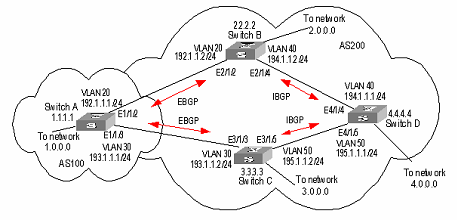
Figure 9-1 Networking diagram for MBGP path selection configuration
III. Configuration procedure
1) Configure Switch A:
<SwitchA> system-view
System View: return to User View with Ctrl+Z.
[SwitchA] vlan 20
[SwitchA-vlan20] port ethernet1/1/2
[SwitchA-vlan20] quit
[SwitchA] interface vlan-interface 20
[SwitchA-Vlan-interface20] ip address 192.1.1.1 255.255.255.0
[SwitchA-Vlan-interface20] quit
[SwitchA] vlan 30
[SwitchA-vlan30] port ethernet1/1/3
[SwitchA-vlan30] quit
[SwitchA] interface vlan-interface 30
[SwitchA-Vlan-interface30] ip address 193.1.1.1 255.255.255.0
[SwitchA-Vlan-interface30] quit
# Enable MBGP.
[SwitchA] bgp 100
[SwitchA-bgp] ipv4-family multicast
# Specify target network for MBGP.
[SwitchA-bgp-af-mul] network 1.0.0.0
[SwitchA-bgp-af-mul] network 2.0.0.0
[SwitchA-bgp-af-mul] quit
# Configure peers relationship.
[SwitchA-bgp] bgp 100
[SwitchA-bgp] group a1 external
[SwitchA-bgp] peer 192.1.1.2 group a1 as-number 200
[SwitchA-bgp] group a2 external
[SwitchA-bgp] peer 193.1.1.2 group a2 as-number 200
[SwitchA-bgp] ipv4-family multicast
[SwitchA-bgp-af-mul] peer a1 enable
[SwitchA-bgp-af-mul] peer a2 enable
# Configure the MED attribute of Switch A.
l Add an ACL on Switch A to permit network 1.0.0.0.
[SwitchA] acl number 2000
[SwitchA-acl-basic-2000] rule permit source 1.0.0.0 0.255.255.255
[SwitchA-acl-basic-2000] rule deny source any
l Define two routing policies: set_med_50 and set_med_100, providing two MED values for network 1.0.0.0 (50 and 100 respectively).
[SwitchA] route-policy set_med_50 permit node 10
[SwitchA-route-policy] if-match acl 2000
[SwitchA-route-policy] apply cost 50
[SwitchA-route-policy] quit
[SwitchA] route-policy set_med_100 permit node 10
[SwitchA-route-policy] if-match acl 2000
[SwitchA-route-policy] apply cost 100
l Apply the routing policy set_med_50 to the exported route updates of Switch C (193.1.1.2). Apply the routing policy set_med_100 to the exported route updates of Switch B (192.1.1.2).
[SwitchA] bgp 100
[SwitchA-bgp] ipv4-family multicast
[SwitchA-bgp-af-mul] peer a2 route-policy set_med_50 export
[SwitchA-bgp-af-mul] peer a1 route-policy set_med_100 export
2) Configure Switch B:
<SwitchB> system-view
System View: return to User View with Ctrl+Z.
[SwitchB] vlan 20
[SwitchB-vlan20] port ethernet2/1/2
[SwitchB-vlan20] quit
[SwitchB] interface vlan-interface 20
[SwitchB-Vlan-interface20] ip address 192.1.1.2 255.255.255.0
[SwitchB-Vlan-interface20] quit
[SwitchB] vlan 40
[SwitchB-vlan40] port ethernet2/1/4
[SwitchB-vlan40] quit
[SwitchB] interface vlan-interface 40
[SwitchB-Vlan-interface40] ip address 194.1.1.2 255.255.255.0
[SwitchB-Vlan-interface40] quit
[SwitchB] ospf
[SwitchB-ospf-1] area 0
[SwitchB-ospf-1-area-0.0.0.0] network 194.1.1.0 0.0.0.255
[SwitchB-ospf-1-area-0.0.0.0] network 192.1.1.0 0.0.0.255
[SwitchB-ospf-1-area-0.0.0.0] quit
[SwitchB-ospf-1] quit
[SwitchB] bgp 200
[SwitchB-bgp] undo synchronization
[SwitchB-bgp] group b1 external
[SwitchB-bgp] peer 192.1.1.1.1 group b1 as-number 100
[SwitchB-bgp] group b2 internal
[SwitchB-bgp] peer 194.1.1.1.1 group b2
[SwitchB-bgp] peer 195.1.1.1.2 group b2
[SwitchB-bgp] ipv4-family multicast
[SwitchB-bgp-af-mul] peer b1 enable
[SwitchB-bgp-af-mul] peer b2 enable
3) Configure Switch C:
<SwitchC> system-view
System View: return to User View with Ctrl+Z.
[SwitchC] vlan 30
[SwitchC-vlan30] port ethernet3/1/3
[SwitchC-vlan30] quit
[SwitchC] interface vlan-interface 30
[SwitchC-Vlan-interface30] ip address 193.1.1.2 255.255.255.0
[SwitchC-Vlan-interface30] quit
[SwitchC] vlan 50
[SwitchC-vlan50] port ethernet3/1/5
[SwitchC-vlan50] quit
[SwitchC] interface vlan-interface 50
[SwitchC-Vlan-interface50] ip address 195.1.1.2 255.255.255.0
[SwitchC-Vlan-interface50] quit
[SwitchC] ospf
[SwitchC-ospf-1] area 0
[SwitchC-ospf-1-area-0.0.0.0] network 193.1.1.0 0.0.0.255
[SwitchC-ospf-1-area-0.0.0.0] network 195.1.1.0 0.0.0.255
[SwitchC-ospf-1-area-0.0.0.0] quit
[SwitchC-ospf-1] quit
[SwitchC] bgp 200
[SwitchC-bgp] undo synchronization
[SwitchC-bgp] group c1 external
[SwitchC-bgp] peer 193.1.1.1 group c1 as-number 100
[SwitchC-bgp] group c2 internal
[SwitchC-bgp] peer 194.1.1.2 group c2
[SwitchC-bgp] peer 195.1.1.1 group c2
[SwitchC-bgp] ipv4-family multicast
[SwitchC-bgp-af-mul] peer c1 enable
[SwitchC-bgp-af-mul] peer c2 enable
# Configure the local preference attribute of Switch C.
l Add ACL 2000 on Switch C to permit network 1.0.0.0.
[SwitchC] acl number 2000
[SwitchC-acl-basic-2000] rule permit source 1.0.0.0 0.255.255.255
[SwitchC-acl-basic-2000] quit
l Define the routing policy named "localpref". Set the local preference for the routes matching ACL 2000 to 200, and otherwise, to 100.
[SwitchC] route-policy localpref permit node 10
[SwitchC-route-policy] if-match acl 2000
[SwitchC-route-policy] apply local-preference 200
[SwitchC-route-policy] quit
[SwitchC] route-policy localpref permit node 20
[SwitchC-route-policy] apply local-preference 100
l Apply this routing policy to the inbound traffic from BGP neighbor 193.1.1.1 (Switch A).
[SwitchC] bgp 200
[SwitchC-bgp] ipv4-family multicast
[SwitchC-bgp-af-mul] peer 193.1.1.1 route-policy localpref import
4) Configure Switch D:
<SwitchD> system-view
System View: return to User View with Ctrl+Z.
[SwitchD] vlan 40
[SwitchD-vlan40] port ethernet4/1/4
[SwitchD-vlan40] quit
[SwitchD] interface vlan-interface 40
[SwitchD-Vlan-interface40] ip address 194.1.1.1 255.255.255.0
[SwitchD-Vlan-interface40] quit
[SwitchD] vlan 50
[SwitchD-vlan50] port ethernet4/1/5
[SwitchD-vlan50] quit
[SwitchD] interface vlan-interface 50
[SwitchD-Vlan-interface50] ip address 195.1.1.1 255.255.255.0
[SwitchD-Vlan-interface50] quit
[SwitchD-ospf-1] area 0
[SwitchD-ospf-1-area-0.0.0.0] network 194.1.1.0 0.0.0.255
[SwitchD-ospf-1-area-0.0.0.0] network 195.1.1.0 0.0.0.255
[SwitchD-ospf-1-area-0.0.0.0] network 4.0.0.0 0.0.0.255
[SwitchD-ospf-1-area-0.0.0.0] quit
[SwitchD-ospf-1] quit
[SwitchD] bgp 200
[SwitchD-bgp] undo synchronization
[SwitchD-bgp] group d1 internal
[SwitchD-bgp] peer 194.1.1.2 group d1
[SwitchD-bgp] peer 195.1.1.2 group d1
[SwitchD-bgp] ipv4-family multicast
[SwitchD-bgp-af-mul] peer d1 enable
To make the configuration effective, you need to use the reset bgp all command on all MBGP neighbors.
