- Table of Contents
-
- H3C S9500 Series Routing Switches Operation Manual-(V1.01)
- 00-1Cover
- 01-Getting Started Operation
- 02-Port Operation
- 03-VLAN-QinQ Operation
- 04-Network Protocol Operation
- 05-Routing Protocol Operation
- 06-Multicast Protocol Operation
- 07-QACL Operation
- 08-MPLS Operation
- 09-STP Operation
- 10-Security Operation
- 11-Reliability Operation
- 12-System Management Operation
- 13-PoE Operation
- 14-NAT-URPF-VPLS Operation
- 15-Integrated Management Operation
- 16-Appendix
- Related Documents
-
| Title | Size | Download |
|---|---|---|
| 13-PoE Operation | 125 KB |
Table of Contents
1.1.2 External PSE4500-A Power System
1.3 Comprehensive Configuration Example
Chapter 2 PoE PSU Supervision Configuration
2.1 Introduction to PoE PSU Supervision
2.2 AC Input Alarm Thresholds Configuration
2.2.1 AC Input Alarm Thresholds Configuration Tasks
2.2.2 AC Input Alarm Thresholds Configuration Example
2.3 DC Output Alarm Thresholds Configuration
2.3.1 DC Output Alarm Thresholds Configuration Tasks
2.3.2 DC Output Alarm Thresholds Configuration Example
2.4 Displaying PoE Supervision Information
2.5 PoE PSU Supervision Configuration Example
Chapter 1 PoE Configuration
1.1 PoE Overview
1.1.1 PoE on the Switch
H3C S9500 Series Routing Switches (hereinafter referred to as S9500 series) support power-over-Ethernet (PoE). Equipped with external power supply and PoE-capable cards, S9500 series can provide 48 VDC power for remote powered devices (PDs, such as IP phones, WLAN APs, and Network cameras) through twisted pairs.
l The S9500 series support LEGACY Power Supply standard. While they can also supply power to PDs noncompliant with the standard.
The power supply of the S9500 series is administered by the SRP card; each PoE card on the switch can be viewed as a power sourcing equipment (PSE), which administers the power supplying of all the ports on it independently.
The S9500 series can transmit data and supply power in the mean time through the signal lines (1, 3, 2, and 6) of the category-3/5 twisted pairs. Using converters, they can also supply power to the PDs that can be powered only through spare lines (4, 5, 7, and 8).
l The S9500 series supply power through the Ethernet electrical ports on the service cards. Each service card can supply power to up to 48 remote devices at the maximum distance of 100 m (328 feet).
l The maximum power that can be supplied by each Ethernet port to its PD is 16.8 W.
l When supplying power to remote devices, the maximum total power that can be provided by the S9500 series is 4500 W (220 V)/2250 W (110V). The switch determines whether or not to supply power to the next remote PD it discovered depending on the total power it currently supply.
& Note:
l When a remote PD is powered by an S9500 series switch, the PD needs not have any external power supply.
l If the remote PD has an external power supply, the S9500 series switch and the external power supply will be redundant with each other for the PD.
1.1.2 External PSE4500-A Power System
If PSE4500-A power system is taken as the external power supply of the switch, the power distribution is as follows:
1) Input voltage: 110 VAC
l One or two PSUs (power supply unit) of the PSE4500-A power system can provide 1200 W of power.
l If the PSE4500-A power modules work in 2+1 redundancy backup mode, then each module provides 750 W of power.
2) Input voltage: 220 VAC
l One or two PSUs of the PSE4500-A power system can provide 2500 W of power.
l If the PSE4500-A power modules are in 2+1 redundancy, then each module provides a power of 1500 W.
1.1.3 PoE-Capable Card
The following service card of the S9500 series supports PoE:
l GV48D
1.2 PoE Configuration
The S9500 series can automatically detect any connected device that needs remote power supply and feeds power to this device.
l Depending on your actual network requirement, you can set the maximum PoE power totally supplied by the switch through the command line.
l You can set the maximum PoE power supplied by a card through the command line.
l You can also control the PoE on each PoE port independently through the command line. The control includes: enabling/disabling the PoE feature, and setting the maximum PoE power, the PoE mode and the PoE priority on the port.
1.2.1 PoE Configuration Tasks
The following table describes the PoE configuration tasks on the S9500 series.
Table 1-1 PoE configuration tasks on the S9500 series
|
No |
Item |
Command |
Description |
|
1 |
Enter system view |
system-view |
- |
|
2 |
Enter Ethernet port view |
interface interface-type interface-number |
As a result of this command, a port view prompt is displayed, which varies with the port type you selected. |
|
3 |
Enable PoE on the port |
poe enable |
By default, PoE is disabled on a port. |
|
4 |
Set the maximum PoE power supplied by the port |
poe max-power max-power |
You can set the maximum PoE power supplied by a port depending on the power of the actual PD. By default, the max-power is 16800 mW. |
|
5 |
Set the PoE mode on the port |
poe mode { signal | spare | auto } |
S9500 series supports only signal line PoE mode. By default, the PoE mode on a port is signal. |
|
6 |
Set the PoE priority on the port |
poe priority { critical | high | low } |
You can set the PoE priority on a port depending on the practical situation. By default, the PoE priority on a port is low. |
|
7 |
Display the PoE state of a specific or all ports of the switch |
display poe interface [ interface-name | interface-type interface-num ] |
You can execute this command in any view. Executing the display poe interface command without any option displays the PoE status of all the ports. |
|
8 |
Display the PoE power information of a specific or all ports of the switch |
display poe interface power [ interface-name | interface-type interface-num ] |
You can execute this command in any view. Executing the display poe interface power command without any option displays the PoE power information about all the ports. |
|
9 |
Display the PoE status and PoE power information of each card |
display poe pse |
You can execute this command in any view |
To cancel the configurations, use the corresponding undo commands. For details about the parameters, refer to the Command Manual.
& Note:
l Before setting the maximum power supplied by a card, make sure the remaining power of the switch is no less than the full power of the card, and the power you can set for a card ranges from 37 W to 806 W.
l The reserved power for a blank slot will be recycled automatically by the system if you insert a PoE-incapable card into the slot.
l When a card is almost fully loaded and a new PD is added, the switch will respond to the PD according to the PoE priority set on the port.
l The PoE priority of each port is based on its card. In other words, the switch cannot compare the priorities of ports on different cards.
l The sampling cycle of the power, current and voltage of ports is 1 second; the sampling cycle of the peak power and average power of both cards and ports is 5 minutes
1.3 Comprehensive Configuration Example
I. Network requirements
l Two PoE-capable cards are installed in slots 3 and 5 on an S9500 series routing switch.
l GigabitEthernet3/1/1 through GigabitEthernet3/1/48 are connected with IP phones and GigabitEthernet5/1/1 through GigabitEthernet5/1/48 are connected with access point (AP) devices.
l The IP phones connected to GigabitEthernet3/1/23 and GigabitEthernet3/1/24 do not need PoE.
l GigabitEthernet3/1/48 is reserved for the use of network management, so it needs higher priority.
l Slot 3 is provided with 400 W power and slot 5 is provided with full power.
l The input power of the AP device connected to GigabitEhternet5/1/15 cannot be greater than 9000 mW.
II. Network diagram
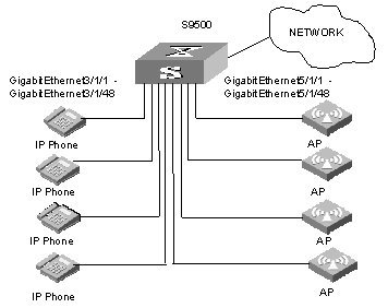
Figure 1-1 PoE remote power supplying
III. Configuration procedure
# Set the maximum power to 400 W on the card in slot 3. By default, the power of each card is full, so the power on the card in slot 5 need not be configured.
[H3C] poe max-power 400 slot 3
# Enable PoE on the ports GigabitEthernet3/1/1 through GigabitEthernet3/1/48.
[H3C-GigabitEthernet3/1/1] poe enable
[H3C-GigabitEthernet3/1/2] poe enable
[H3C-GigabitEthernet3/1/3] poe enable
Go on the configuration till the port GigabitEthernet3/1/48.
# Enable PoE on the ports GigabitEthernet5/1/1 through GigabitEthernet5/1/48.
[H3C-GigabitEthernet5/1/1] poe enable
[H3C-GigabitEthernet5/1/2] poe enable
[H3C-GigabitEthernet5/1/3] poe enable
Go on the configuration till the port GigabitEthernet5/1/48.
# Set the PoE priority of the port GigabitEthernet3/1/48 to critical, the PD connected with GigabitEthernet3/1/48 will be powered in precedence on the premise that other ports' power supplying is not interrupted.
[H3C-GigabitEthernet3/1/48] poe priority critical
# Set the maximum PoE power on the GigabitEthernet5/1/15 port to 9000 mW.
[H3C] interface GigabitEthernet5/1/15
Chapter 2 PoE PSU Supervision Configuration
2.1 Introduction to PoE PSU Supervision
The PoE-capable S9500 series can monitor the external PoE PSUs through the power supervision module on the PoE external power system.
The PoE PSU supervision module enables you to:
l Set the alarm thresholds for the AC input voltages of the PoE PSUs.
l Set the alarm thresholds for the DC output voltages of the PoE PSUs.
l Query PSU information such as voltage and power.
2.2 AC Input Alarm Thresholds Configuration
You can set the AC input alarm thresholds for the PoE PSUs to enable the S9500 series to monitor the AC input voltages of the PSUs in real time through the PoE supervision module.
2.2.1 AC Input Alarm Thresholds Configuration Tasks
Table 2-1 AC input alarm thresholds configuration tasks
|
No |
Item |
Command |
Description |
|
1 |
Enter system view |
system-view |
- |
|
2 |
Set the overvoltage alarm threshold of AC input (upper threshold) for the PoE PSUs |
poe-power input-thresh upper string |
Required, and the max voltage is 264.0 V. |
|
3 |
Set the undervoltage alarm threshold of AC input (lower threshold) for the PoE PSUs |
poe-power input-thresh lower string |
Required, and the min voltage is 90.0 V. |
|
4 |
Display the AC input state of each PoE PSU |
display poe-power ac-input state |
Optional, and you can execute this command in any view. |
& Note:
l You can set the thresholds to any appropriate values in the range, but make sure the lower threshold is less than the upper threshold.
l For 220 VAC input, it is recommended to set the upper threshold to 264 V and the lower threshold to 181 V.
l For 110 VAC input, it is recommended to set the upper threshold to 132 V and the lower threshold to 90 V.
2.2.2 AC Input Alarm Thresholds Configuration Example
I. Network requirements
l Set the overvoltage alarm threshold of AC input for PoE PSUs to 264.0 V.
l Set the undervoltage alarm threshold of AC input for PoE PSUs to 181.0 V.
II. Configuration procedure
# Enter system view.
<H3C> system-view
# Set the overvoltage alarm threshold of AC input for PoE PSUs to 264.0 V.
[H3C] poe-power input-thresh upper 264.0
# Set the undervoltage alarm threshold of AC input for PoE PSUs to 181.0 V.
[H3C] poe-power input-thresh lower 181.0
# Display the information about the AC input for the PoE PSUs.
[H3C] display poe-power ac-input state
2.3 DC Output Alarm Thresholds Configuration
You can set the DC output alarm thresholds for the PoE PSUs to enable the S9500 series to monitor the DC output voltages of the PSUs in real time through the PoE supervision module.
2.3.1 DC Output Alarm Thresholds Configuration Tasks
Table 2-2 DC output alarm thresholds configuration tasks
|
No |
Operation |
Command |
Description |
|
1 |
Enter system view |
system-view |
- |
|
2 |
Set the overvoltage alarm threshold of DC output (upper threshold) for the PoE PSUs |
poe-power output-thresh upper string |
Required, and the range is 55.0 V to 57.0 V. |
|
3 |
Set the undervoltage alarm threshold of DC output (lower threshold) for the PoE PSUs |
poe-power output-thresh lower string |
Required, and the range is 45.0 V to 47.0 V. |
|
4 |
Display the DC output state of the PoE PSUs. |
display poe-power dc-output state |
Optional, and you can execute this command in any view. |
|
5 |
Display the DC output voltage/current value of the PoE PSUs |
display poe-power dc-output value |
Optional, and you can execute this command in any view. |
& Note:
For both 220 VAC and 110 VAC input, it is recommended to set the upper threshold to 57.0 V and the lower threshold to 45.0 V.
2.3.2 DC Output Alarm Thresholds Configuration Example
I. Network requirements
l Set the overvoltage alarm threshold of DC output for the PoE PSUs to 57.0 V.
l Set the undervoltage alarm threshold of DC output for the PoE PSUs to 45.0 V.
II. Configuration procedure
# Enter system view.
<H3C> system-view
# Set the overvoltage alarm threshold of DC output for the PoE PSUs to 57.0 V.
[H3C] poe-power output-thresh upper 57.0
# Set the undervoltage alarm threshold of DC output for the PoE PSUs to 45.0 V.
[H3C] poe-power output-thresh lower 45.0
# Display the DC output state of the PoE PSUs.
[H3C] display poe-power dc-output state
# Display the DC output voltage/current values of the PoE PSUs.
[H3C] display poe-power dc-output value
2.4 Displaying PoE Supervision Information
After completing the above configurations, you can execute the display command in any view to query the PoE state of the switch. Then you can view the display output to check the effect of these configurations.
Table 2-3 Display PoE supervision information
|
No |
Operation |
Command |
Description |
|
1 |
Display the basic information about the PoE PSUs. |
display supervision-module information |
You can execute this command in any view. |
|
2 |
Display detailed alarm information about the PoE PSUs. |
display poe-power alarm |
You can execute this command in any view. |
|
3 |
Display the number and current state of AC power distribution switches of the PSUs. |
display poe-power switch state |
You can execute this command in any view. |
For details about display output, refer to the Command Manual.
2.5 PoE PSU Supervision Configuration Example
I. Network requirements
l Insert a PoE-capable card into slot 3 of the S9500 series routing switch.
l Connect GigabitEthernet3/1/1 to GigabitEthernet3/1/48 to IP phones.
l Set the AC input and DC output alarm thresholds to appropriate values.
II. Network diagram
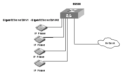
Figure 2-1 Network diagram for PoE supervision configuration
III. Configuration procedure
# Enter system view.
<H3C> system-view
# Set the overvoltage alarm threshold of AC input for PoE PSUs to 264.0 V.
[H3C] poe-power input-thresh upper 264.0
# Set the undervoltage alarm threshold of AC input for PoE PSUs to 181.0 V.
[H3C] poe-power input-thresh lower 181.0
# Set the overvoltage alarm threshold of DC output for the PoE PSUs to 57.0 V.
[H3C] poe-power output-thresh upper 57.0
# Set the undervoltage alarm threshold of DC output for the PoE PSUs to 45.0 V.
[H3C] poe-power output-thresh lower 45.0
