- Table of Contents
-
- H3C S9500 Series Routing Switches Operation Manual-(V1.01)
- 00-1Cover
- 01-Getting Started Operation
- 02-Port Operation
- 03-VLAN-QinQ Operation
- 04-Network Protocol Operation
- 05-Routing Protocol Operation
- 06-Multicast Protocol Operation
- 07-QACL Operation
- 08-MPLS Operation
- 09-STP Operation
- 10-Security Operation
- 11-Reliability Operation
- 12-System Management Operation
- 13-PoE Operation
- 14-NAT-URPF-VPLS Operation
- 15-Integrated Management Operation
- 16-Appendix
- Related Documents
-
| Title | Size | Download |
|---|---|---|
| 12-System Management Operation | 781 KB |
Table of Contents
Chapter 1 File System Management
1.1.4 Storage Device Operation
1.1.5 Setting the Prompt Mode of the File System
1.2 Configuration File Management
1.2.1 Configuration File Management Overview
1.2.2 Displaying the Current-Configuration and Saved-Configuration of Ethernet Switch.
1.2.3 Modifying and Saving the Current-Configuration
1.2.4 Erasing Configuration Files from Flash Memory
1.2.5 Configuring the Name of the Configuration File Used for the Next Startup.
1.3.2 Enabling/Disabling FTP Server
1.3.3 Configuring the FTP Server Authentication and Authorization
1.3.4 Configuring the Running Parameters of FTP Server
1.3.5 Displaying and Debugging FTP Server
1.3.6 Disconnecting an FTP User
1.3.7 Introduction to FTP Client
1.3.8 FTP Client Configuration Example
1.3.9 FTP Server Configuration Example
1.4.2 Downloading Files by Means of TFTP
1.4.3 Uploading Files by Means of TFTP
1.4.4 TFTP Client Configuration Example
Chapter 2 MAC Address Table Management
2.1 MAC Address Table Management Overview
2.2 MAC Address Table Management Configuration
2.2.1 Setting MAC Address Table Entries
2.2.2 Setting MAC Address Aging Time
2.3 Maximum MAC Address Number Learned by Ethernet Port and Forwarding Option Configuration
2.3.1 Maximum MAC Address Number Learned by a Port and Forwarding Option Configuration Tasks
2.3.2 Configuring Maximum MAC Address Number Learned by Ethernet Port and Forwarding Option Example
2.4 Configuring Max Number of MAC Addresses That Can Be Learned in a VLAN
2.5 Displaying and Debugging MAC Address Tables
2.7 MAC Address Table Management Configuration Example
3.1 Device Management Overview
3.2 Device Management Configuration
3.2.1 Rebooting the Ethernet Switch
3.2.2 Enabling the Timing Reboot Function
3.2.3 Specifying the Bootstrap Programs for the Routing Switch
3.2.5 Setting Slot Temperature Limit
3.2.6 Updating Service Processing Boards
3.3 Displaying and Debugging Device Management
3.4 Device Management Configuration Example
3.4.1 Using the Switch as an FTP Client to Implement the Remote Upgrade (S9505 as example)
3.4.2 Use the Switch as an FTP Server to Implement the Remote Upgrade (S9505 as example)
Chapter 4 System Maintenance and Debugging
4.1 Basic System Configuration
4.1.1 Setting a Name for a Switch
4.1.2 Setting the System Clock
4.2 Displaying the State and Information of the System
4.3.1 Enabling/Disabling the Terminal Debugging
4.3.2 Displaying Diagnostic Information
4.4 Testing Tools for Network Connection
4.5.1 Introduction to Info-center
4.5.2 Info-center Configuration
4.5.3 Sending the Configuration Information to the Loghost
4.5.4 Sending the Configuration Information to Console terminal
4.5.5 Sending the Configuration Information to Telnet Terminal or Dumb Terminal
4.5.6 Sending the Configuration Information to the Log Buffer
4.5.7 Sending the Configuration Information to the Trap Buffer
4.5.8 Sending the Configuration Information to SNMP Network Management
4.5.9 Displaying and Debugging Info-center
4.5.10 Configuration Examples of Sending Log to the Unix Loghost
4.5.11 Configuration examples of sending log to Linux loghost
4.5.12 Configuration Examples of Sending Log to the Console Terminal
4.6.1 Introduction to Clock Module
4.6.2 Configuring Clock Module
5.2 SNMP Versions and Supported MIB
5.3.2 Setting the System Information
5.3.3 Enabling/Disabling SNMP Agent to Send Trap
5.3.4 Setting the Destination Address of Trap
5.3.5 Setting Lifetime of Trap Message
5.3.6 Setting the Engine ID of a Local or Remote Device
5.3.7 Setting/Deleting an SNMP Group
5.3.8 Setting the Source Address of Trap
5.3.9 Adding/Deleting a User to/from an SNMP Group
5.3.10 Creating/Updating View Information or Deleting a View
5.3.11 Setting the Size of the SNMP Packet Sent/Received by an Agent
5.4 Displaying and Debugging SNMP
5.5 SNMP Configuration Example
6.2.1 Adding/Deleting an Entry to/from the Event Table
6.2.2 Adding/Deleting an Entry to/from the Alarm Table
6.2.3 Adding/Deleting an Entry to/from the Extended RMON Alarm Table
6.2.4 Adding/Deleting an Entry to/from the History Control Table
6.2.5 Adding/Deleting an Entry to/from the Statistics Table
6.3 Displaying and Debugging RMON
6.4 RMON Configuration Example
7.1.2 Basic Operating Principle of NTP
7.2.1 Configuring NTP Operating Mode
7.2.2 Configuring NTP ID Authentication
7.2.3 Setting NTP Authentication Key
7.2.4 Setting Specified Key as Reliable
7.2.5 Designating an Interface to Transmit NTP Messages
7.2.6 Setting NTP Master Clock
7.2.7 Setting Authority to Access a Local Ethernet Switch
7.2.8 Setting Maximum Local Sessions
7.3 Displaying and Debugging NTP
7.4.1 Configuring a NTP Server
7.4.2 NTP Peer Configuration Example
7.4.3 Configure NTP Broadcast Mode
7.4.4 Configure NTP Multicast Mode
7.4.5 Configure Authentication-Enabled NTP Server Mode
Chapter 8 SSH Terminal Service
8.1.2 SSH Server Configuration
8.1.3 SSH Client Configuration
8.1.4 Displaying and Debugging SSH
8.1.5 SSH Server Configuration Example
8.1.6 SSH Client Configuration Example
8.2.2 SFTP Server Configuration
8.2.3 SFTP Client Configuration
8.2.4 SFTP Configuration Example
Chapter 1 File System Management
1.1 File System Configuration
1.1.1 File System Overview
The Ethernet switch provides a file system module for user’s efficient management over the storage devices such as Flash memory. The file system offers file access and directory management, mainly including creating the file system, creating, deleting, modifying and renaming a file or a directory and opening a file.
By default, the file system needs user’s confirmation before executing the commands, such as deleting or overwriting a file, which may make losses.
Based on the operated objects, the file system operation can be divided as follows. The following sections describe the file system configuration tasks.
l Setting the Prompt Mode of the File System
& Note:
H3C S9500 series routing switches (hereinafter referred to as S9500 series) support master/slave SRPU switchover. The two boards both have a program system. The program user can operate the programs on both boards. When you specify the bootstrap APP program for use by the slave board at the next startup, make sure that the URL of the program starts with “slot[No.]#[flash: | cf:]/”, where [No.] is the slave board number, and [flash: | cf:] is the name of the equipment, which can be a flash card of CR card. For example, if the slave board is on slot 1, the URL of 9500.app program on the slave board is “slot1#flash:/9500.app”.
1.1.2 Directory Operation
The file system can be used to create or delete a directory, display the current working directory, and display the information about the files or directories under a specified directory. You can use the following commands to perform directory operations.
Perform the following configuration in user view.
|
Operation |
Command |
|
Create a directory |
mkdir directory |
|
Delete a directory |
rmdir directory |
|
Display the current working directory |
pwd |
|
Display the information about directories or files |
dir [ / all ] [ file-url ] |
|
Change the current directory |
cd directory |
1.1.3 File Operation
The file system can be used to delete or undelete a file and permanently delete a file. Also, it can be used to display file contents, rename, copy and move a file and display the information about a specified file. You can use the following commands to perform file operations.
Perform the following configuration in user view.
|
Operation |
Command |
|
Delete a file |
delete [ /unreserved ] file-url |
|
Undelete a file |
undelete file-url |
|
Delete a file from the recycle bin permanently |
reset recycle-bin [ file-url ] |
|
View contents of a file |
more file-url |
|
Rename a file |
rename fileurl-source fileurl-dest |
|
Copy a file |
copy fileurl-source fileurl-dest |
|
Move a file |
move fileurl-source fileurl-dest |
|
Display the information about directories or files |
dir [ / all ] [ file-url ] |
|
Execute the specified batch file (system view) |
execute filename |
![]() Caution:
Caution:
When you use the delete command without the unreserved option to delete a file, the file is in fact saved in the recycle bin and still occupies some of the storage space. So, the frequent uses of this command may results in insufficient storage space of the Ethernet switch., In this case, you should find out the unused files kept in the recycle bin and permanently delete them with the reset recycle-bin command to reclaim the storage space.
& Note:
The directory and file names on the switch have the following limitation:
l The maximum length of a directory or file name is 64 characters.
l The maximum length of a full path name (containing the device name, directory name and file name) is 136 characters.
l The move command takes effect only when the source and destination files are in the same device.
1.1.4 Storage Device Operation
The file system can be used to format a specified memory device. You can use the following commands to format a specified memory device.
Switch supports compact flash (CF) card. After a CF card is inserted successfully, you can use such common commands as dir, cd, copy, delete, move to perform operations on the files in the card. You can also stop the CF card through a command before dismounting it.
Perform the following configuration in user view.
Table 1-3 Storage device operation
|
Operation |
Command |
|
Format the storage device |
format filesystem |
|
Restore the space of the storage device |
fixdisk device |
|
Delete the CF card |
umount device |
1.1.5 Setting the Prompt Mode of the File System
The following command can be used for setting the prompt mode of the current file system.
Perform the following configuration in system view.
Table 1-4 File system operation
|
Operation |
Command |
|
Set the file system prompt mode. |
file prompt { alert | quiet } |
1.2 Configuration File Management
1.2.1 Configuration File Management Overview
The management module of configuration file provides a user-friendly operation interface. It saves the configuration of the Ethernet switch in the text format of command line to record the whole configuration process. Thus you can view the configuration information conveniently.
The format of configuration file includes:
l It is saved in the command format.
l Only the non-default constants will be saved
l The organization of commands is based on command views. The commands in the same command mode are sorted in one section. The sections are separated with a blank line or a comment line (A comment line begins with exclamation mark “#”).
l Generally, the sections in the file are arranged in the following order: system configuration, Ethernet port configuration, VLAN interface configuration, routing protocol configuration and so on.
l It ends with “end”.
The following sections describe configuration file management tasks.
l Displaying the Current-Configuration and Saved-Configuration of Ethernet Switch
l Modifying and Saving the Current-Configuration
l Erasing Configuration Files from Flash Memory
l Configuring the Name of the Configuration File Used for the Next Startup.
1.2.2 Displaying the Current-Configuration and Saved-Configuration of Ethernet Switch
After being powered on, the system will read the configuration files from Flash Memory for the initialization of the device. (Such configuration files are called saved-configuration files). If there is no configuration file in Flash Memory, the system will begin the initialization with the default parameters. Relative to the saved-configuration, the configuration in effect during the operating process of the system is called current-configuration. You can use the following commands to display the current-configuration and saved-configuration information of the Ethernet switch.
Perform the following configuration in any view.
Table 1-5 Display the configurations of the Ethernet switch
|
Operation |
Command |
|
Display the saved-configuration information of the Ethernet switch |
display saved-configuration |
|
Display the current-configuration information of the Ethernet switch |
display current-configuration [ controller | interface interface-type interface-number | configuration [ configuration ] ] [ | { begin | exclude | include } regular-expression ] |
|
Display the running configuration of the current view |
display this |
& Note:
The configuration files are displayed in their corresponding saving formats.
1.2.3 Modifying and Saving the Current-Configuration
You can modify the current configuration of Ethernet switch through the CLI. Use the save command to save the current-configuration in the Flash Memory, and the configurations will become the saved-configuration when the system is powered on for the next time.
Perform the following configuration in user view.
Table 1-6 Save the current-configuration
|
Operation |
Command |
|
Save the current-configuration |
save [ file-name ] |
Even if the problems like reboot and power-off occur during , the configuration file can be still saved to Flash.
1.2.4 Erasing Configuration Files from Flash Memory
The reset saved-configuration command can be used to erase configuration files from Flash Memory. The system will use the default configuration parameters for initialization when the Ethernet switch is powered on for the next time.
Perform the following configuration in user view.
Table 1-7 Erase configuration files from Flash Memory
|
Operation |
Command |
|
Erase configuration files from Flash Memory |
reset saved-configuration |
You may erase the configuration files from the Flash in the following cases:
l After being upgraded, the software does not match with the configuration files.
l The configuration files in flash are damaged. (A common case is that a wrong configuration file has been downloaded.)
1.2.5 Configuring the Name of the Configuration File Used for the Next Startup.
Perform the following configuration in user view.
Table 1-8 Configure the name of the configuration file used for the next startup
|
Operation |
Command |
|
Configure the name of the configuration file used for the next startup |
startup saved-configuration cfgfile |
cfgfile is the name of the configuration file and its extension name can be “.cfg”. The file is stored in the root directory of the storage devices.
After the above configuration, execute display command in any view to display the running of the configuration files, and to verify the effect of the configuration.
Table 1-9 Display the information of the file used at startup
|
Operation |
Command |
|
Display the information of the file used at startup |
display startup |
1.3 FTP Configuration
& Note:
The system supports FTP services over VPN.
1.3.1 FTP Overview
FTP (File Transfer Protocol) is a universal method for transmitting files on the Internet and IP networks. In this method, files are copied from one system to another. FTP supports definite file types (such as ASCII and Binary) and file structures (byte stream and record). Even now, FTP is still used widely, while most users transmit files by Email and Web.
FTP, a TCP/IP protocol on the application layer, is used for transmitting files between a remote server and a local host.
The Ethernet switch provides the following FTP services:
l FTP server: You can run FTP client program to log in the server and access the files on it.
l FTP client: You can run the ftp X.X.X.X command (where, X.X.X.X represents the IP address of the remote FTP server) to set up a connection between the Ethernet switch and a remote FTP server to access the files on the remote server.
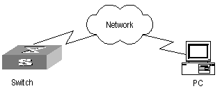
Table 1-10 lists the configuration of the switch as FTP client.
Table 1-10 Configuration of the switch as FTP client
|
Device |
Configuration |
Default |
Description |
|
Switch |
Log into the remote FTP server directly with the ftp command. |
- |
You need first get FTP user command and password, and then log into the remote FTP server. Then you can get the directory and file authority. |
|
PC |
Start FTP server and make such settings as username, password, and authority. |
- |
- |
Table 1-11 lists the configuration of the switching as FTP server.
Table 1-11 Configuration of the switch as FTP server
|
Device |
Configuration |
Default |
Description |
|
Switch |
Start FTP server. |
FTP server is disabled |
You can view the configuration information of FTP server with the display ftp-server command |
|
Configure authentication and authorization for FTP server. |
- |
Configure username, password and authorized directory for FTP users |
|
|
Configure running parameters for FTP server. |
- |
Configure timeout time value for FTP server. |
|
|
PC |
Log into the switch from FTP client. |
- |
- |
![]() Caution:
Caution:
The prerequisite for normal FTP function is that the switch and PC are reachable.
1.3.2 Enabling/Disabling FTP Server
You can use the following commands to enable/disable the FTP server on the switch. Perform the following configuration in system view.
Table 1-12 Enable/disable FTP Server
|
Operation |
Command |
|
Enable the FTP server |
ftp server enable |
|
Disable the FTP server |
undo ftp server |
FTP server supports multiple users to access at the same time. A remote FTP client sends request to the FTP server. Then, the FTP server will carry out the corresponding operation and return the result to the client.
By default, FTP server is disabled.
1.3.3 Configuring the FTP Server Authentication and Authorization
The authorization information of FTP server includes the path to the desired directory for FTP users. The FTP server service is available only for the authenticated and authorized users. The authorization information of FTP server includes the top working directory provided for FTP clients. You can use the following commands to configure FTP server authentication and authorization.
Perform the following configuration in corresponding view.
Table 1-13 Configure the FTP Server Authentication and Authorization
|
Operation |
Command |
|
Create new local FTP user and enter local user view (in System view) |
local-user { username | multicast [ domain domain-name ] ipaddress | password-display-mode { auto | cipher-force } } |
|
Delete local FTP user (in system view) |
undo local-user { username | all [ service-type { ftp | lan-access | telnet | ppp | ssh | terminal } ] | multicast [ domain domain-name ] ipaddress | password-display-mode } |
|
Set the password display mode when the switch displays local user information |
local-user password-display-mode { auto | cipher-force } |
|
Restore the password display mode when the switch displays local user information |
undo local-user password-display-mode |
|
Configure password for local user(local user view) |
password { cipher | simple } password |
|
Configure service type for local user(local user view) |
service-type { ftp [ ftp-directory directory ] | lan-access | ppp [ call-number call-number | callback-nocheck | callback-number callback-number ] | ssh [ level level | telnet | terminal ] | telnet [ level level | ssh | temninal ] | terminal [ level level | ssh | telnet ] } |
|
Cancel password for local user(local user view) |
undo password |
|
Cancel authorization information for FTP user(local user view) |
undo service-type { ftp [ ftp-directory directory ] | lan-access | ppp [ call-number call-number | callback-nocheck | callback-number callback-number ] | ssh [ level level | telnet | terminal ] | telnet [ level level | ssh | temninal ] | terminal [ level level | ssh | telnet ] } |
Only the clients who have passed the authentication and authorization successfully can access the FTP server.
1.3.4 Configuring the Running Parameters of FTP Server
You can use the following commands to configure the connection timeout of the FTP server. If the FTP server receives no service request from the FTP client for a period of time, it will cut the connection to it, thereby avoiding the illegal access from the unauthorized users. The period of time is FTP connection timeout.
Perform the following configuration in system view.
Table 1-14 Configuring FTP server connection timeout
|
Operation |
Command |
|
Configure FTP server connection timeouts |
ftp timeout minute |
|
Restoring the default FTP server connection timeouts |
undo ftp timeout |
By default, the FTP server connection timeout is 30 minutes.
1.3.5 Displaying and Debugging FTP Server
Table 1-15 Display and debug FTP Server
|
Operation |
Command |
|
Display FTP server |
display ftp-server |
|
Display the connected FTP users. |
display ftp-user |
The display ftp-server command can be used for displaying the configuration information about the current FTP server, including the maximum amount of users supported by FTP server and the FTP connection timeout. The display ftp-user command can be used for displaying the detail information about the connected FTP users.
1.3.6 Disconnecting an FTP User
Perform the following configuration in system view.
Table 1-16 Disconnect an FTP user
|
Operation |
Command |
|
Disconnect an FTP user. |
ftp disconnect user-name |
1.3.7 Introduction to FTP Client
As an additional function provided by Ethernet switch, FTP client is an application module and has no configuration functions. The switch connects the FTP clients and the remote server and inputs the command from the clients for corresponding operations (such as creating or deleting a directory).
1.3.8 FTP Client Configuration Example
I. Network requirements
The switch serves as FTP client and the remote PC as FTP server. The configuration on FTP server: Configure an FTP user named as switch, with password hello and with read & write authority over the Switch root directory on the PC. The IP address of a VLAN interface on the switch is 1.1.1.1, and that of the PC is 2.2.2.2. The switch and PC are reachable.
The switch application switch.app is stored on the PC. Using FTP, the switch can download the switch.app from the remote FTP server and upload the config.txt to the FTP server under the switch directory for backup purpose.
II. Network diagram
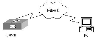
Figure 1-2 Network diagram for FTP configuration
III. Configuration procedure
1) Configure FTP server parameters on the PC: a user named as switch, password hello, read and write authority over the Switch directory on the PC.
2) Configure the switch
# Log into the switch through the Console port locally or Telnet remotely.
Then type in the right command in user view to establish FTP connection, then correct username and password to log into the FTP server.
<H3C> ftp 2.2.2.2
Trying ...
Press CTRL+K to abort
Connected.
220 WFTPD 2.0 service (by Texas Imperial Software) ready for new user
User(none):switch
331 Give me your password, please
Password:*****
230 Logged in successfully
[ftp]
![]() Caution:
Caution:
If the Flash Memory of the switch is not enough, you need to first delete the existing programs in the Flash Memory and then upload the new ones.
# Enter the authorized directory of the FTP server.
[ftp] cd switch
# Use the put command to upload the config.txt to the FTP server.
[ftp] put config.txt
# Use the get command to download the switch.app from the FTP server to the Flash directory on the FTP server.
[ftp] get switch.app
# Use the quit command to release FTP connection and return to user view.
[ftp] quit
<H3C>
# Use the boot boot-loader command to specify the downloaded program as the application at the next login and reboot the switch.
<H3C> boot boot-loader switch.app
<H3C> reboot
1.3.9 FTP Server Configuration Example
I. Network requirements
Switch serves as FTP server and the remote PC as FTP client. The configuration on FTP server: Configure an FTP user named as switch, with password hello and with read & write authority over the flash root directory on the PC. The IP address of a VLAN interface on the switch is 1.1.1.1, and that of the PC is 2.2.2.2. The switch and PC are reachable.
The switch application switch.app is stored on the PC. Using FTP, the PC can upload the switch.app from the remote FTP server and download the config.txt from the FTP server for backup purpose.
II. Network diagram

Figure 1-3 Network diagram for FTP configuration
III. Configuration procedure
1) Configure the switch
# Log into the switch through the console port locally or Telnet remotely, and start FTP function and set username, password and file directory.
[H3C] ftp server enable
[H3C] local-user switch
[H3C-luser-switch] service-type ftp ftp-directory flash:
[H3C-luser-switch] password simple hello
2) Run FTP client on the PC and establish FTP connection. Upload the switch.app to the switch under the Flash directory and download the config.txt from the switch. FTP client is not shipped with the switch, so you need to buy it separately.
![]() Caution:
Caution:
If the Flash Memory of the switch is not enough, you need to first delete the existing programs in the Flash Memory and then upload the new ones.
3) When the uploading is completed, initiate file upgrade on the switch.
# Use the boot boot-loader command to specify the downloaded program as the application at the next login and reboot the switch.
<H3C> boot boot-loader switch.app
<H3C> reboot
1.4 TFTP Configuration
1.4.1 TFTP Overview
Trivial File Transfer Protocol (TFTP) is a simple file transmission protocol. It is initially designed for the booting of free-disk systems (work stations or X terminals in general). Compared with FTP, another file transmission protocol, TFTP has no complicated interactive access interface or authentication control, and therefore it can be used when there is no complicated interaction between the clients and server. TFTP is implemented on the basis of UDP.
TFTP transmission is originated from the client end. To download a file, the client sends a request to the TFTP server and then receives data from it and sends acknowledgement to it. To upload a file, the client sends a request to the TFTP server and then transmits data to it and receives the acknowledgement from it. TFTP transmits files in two modes, binary mode for program files and ASCII mode for text files.
The administrator needs to configure the IP addresses of TFTP client and server before configuring TFTP, and makes sure that the route between the client and server is reachable.
The switch can only function as a TFTP client.
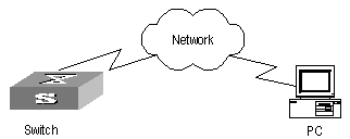
Table 1-17 lists the configuration of the switch as TFTP client.
Table 1-17 Configuration of the switch as TFTP client
|
Device |
Configuration |
Default |
Description |
|
Switch |
Configure IP address for the VLAN interface of the switch, in the same network segment as that of TFTP server. |
- |
TFTP is right for the case where no complicated interactions are required between the client and server. Make sure that the route is reachable between the switch and the TFTP server. |
|
Use the tftp command to log into the remote TFTP server for file uploading and downloading. |
- |
- |
|
|
PC |
Start TFTP server and set authorized TFTP directory. |
- |
- |
1.4.2 Downloading Files by Means of TFTP
To download a file, the client sends a request to the TFTP server and then receives data from it and sends acknowledgement to it. You can use the following commands to download files by means of TFTP.
Perform the following configuration in user view.
Table 1-18 Download files by means of TFTP
|
Operation |
Command |
|
Download files by means of TFTP |
tftp tftp-server get source-file [ dest-file ] |
In the command, tftp-server indicates the IP address or host name of TFTP server; source-file indicates the file information to be downloaded from TFTP server; dest-file indicates the name of the file downloaded on switch.
1.4.3 Uploading Files by Means of TFTP
To upload a file, the client sends a request to the TFTP server and then transmits data to it and receives the acknowledgement from it. You can use the following commands to upload files.
Perform the following configuration in user view.
Table 1-19 Upload files by means of TFTP
|
Operation |
Command |
|
Upload files by means of TFTP |
tftp tftp-server put source-file [ dest-file ] |
In the command, source-file indicates the file to be uploaded to server; dest-file indicates the saved-as name of the file on TFTP server; tftp-server indicates the IP address or host name of TFTP server.
1.4.4 TFTP Client Configuration Example
I. Network requirements
The switch serves as TFTP client and the remote PC as TFTP server. Authorized TFTP directory is set on the TFTP server. The IP address of a VLAN interface on the switch is 1.1.1.1, and that of the PC is 1.1.1.2.
The switch application switch.app is stored on the PC. Using TFTP, the switch can download the switch.app from the remote TFTP server and upload the config.txt to the TFTP server under the switch directory for backup purpose.
II. Network diagram
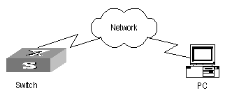
Figure 1-5 Network diagram for TFTP configuration
III. Configuration procedure
1) Start TFTP server on the PC and set authorized TFTP directory.
2) Configure the switch
# Log into the switch (through local console or remote Telnet, refer to the Getting Started for login information), and then enter the system view.
<H3C> system-view
[H3C]
![]() Caution:
Caution:
If the Flash Memory of the switch is not enough, you need to first delete the existing programs in the Flash Memory and then upload the new ones.
# Configure IP address 1.1.1.1 for the VLAN interface, ensure the port connecting the PC is also in this VALN (VLAN 1 in this example).
[H3C] interface vlan 1
[H3C-vlan-interface1] ip address 1.1.1.1 255.255.255.0
[H3C-vlan-interface1] quit
# Enter system view and download the switch.app from the TFTP server to the Flash Memory of the switch.
<H3C> tftp 1.1.1.2 get switch.app switch.app
# Upload the config.txt to the TFTP server.
<H3C> tftp 1.1.1.2 put config.txt config.txt
# Use the boot boot-loader command to specify the downloaded program as the application at the next login and reboot the switch.
<H3C> boot boot-loader switch.app
<H3C> reboot
Chapter 2 MAC Address Table Management
2.1 MAC Address Table Management Overview
An Ethernet Switch maintains a MAC address table for fast forwarding packets. A table entry includes the MAC address of a device and the port ID of the Ethernet switch connected to it. The dynamic entries (not configured manually) are learned by the Ethernet switch. The Ethernet switch learns a MAC address in the following way: after receiving a data frame from a port (assumed as port A), the switch analyzes its source MAC address (assumed as MAC_SOURCE) and considers that the packets destined at MAC_SOURCE can be forwarded through the port A. If the MAC address table contains the MAC_SOURCE, the switch will update the corresponding entry; otherwise, it will add the new MAC address (and the corresponding forwarding port) as a new entry to the table.
The system forwards the packets whose destination addresses can be found in the MAC address table directly through the hardware and broadcasts those packets whose addresses are not contained in the table. The network device will respond after receiving a broadcast packet and the response contains the MAC address of the device, which will then be learned and added into the MAC address table by the Ethernet switch. The consequent packets destined the same MAC address can be forwarded directly thereafter.
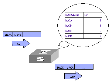
Figure 2-1 The Ethernet switch forwards packets with MAC address table
The Ethernet switch also provides the function of MAC address aging. If the switch receives no packet for a period of time, it will delete the related entry from the MAC address table. However, this function takes no effect on the static MAC addresses.
You can configure (add or modify) the MAC address entries manually according to the actual networking environment. The entries can be static ones or dynamic ones.
2.2 MAC Address Table Management Configuration
The following sections describe the MAC address table management configuration tasks.
l Setting MAC Address Table Entries
l Setting MAC Address Aging Time
l Maximum MAC Address Number Learned by Ethernet Port and Forwarding Option Configuration
l Maximum MAC Address Number Learned by Ethernet Port and Forwarding Option Configuration
2.2.1 Setting MAC Address Table Entries
Administrators can manually add, modify, or delete the entries in MAC address table according to the actual needs. They can also delete all the (unicast) MAC address table entries related to a specified port or delete a specified type of entries, such as dynamic entries or static entries.
You can use the following commands to add, modify, or delete the entries in MAC address table.
Perform the following configuration in system view.
Table 2-1 Set MAC address table entries
|
Operation |
Command |
|
Add/Modify an address entry |
mac-address { static | dynamic } mac-addr interface interface-type interface-number vlan vlan-id |
|
Delete an address entry |
undo mac-address [ static | dynamic ] [ mac-addr [ interface interface-type interface-number ] vlan vlan-id | interface interface-type interface-number | vlan vlan-id ] |
2.2.2 Setting MAC Address Aging Time
The setting of an appropriate aging time can effectively implement the function of MAC address aging. Too long or too short aging time set by subscribers will cause the problem that the Ethernet switch broadcasts a great mount of data packets without MAC addresses, which will affect the switch operation performance.
If aging time is set too long, the Ethernet switch will store a great number of out-of-date MAC address tables. This will consume MAC address table resources and the switch will not be able to update MAC address table according to the network change.
If aging time is set too short, the Ethernet switch may delete valid MAC address table.
You can use the following commands to set the MAC address aging time for the system.
Perform the following configuration in system view.
Table 2-2 Set the MAC address aging time for the system
|
Operation |
Command |
|
Set the dynamic MAC address aging time |
mac-address timer { aging age | no-aging } |
|
Restore the default MAC address aging time |
undo mac-address timer aging |
In addition, this command takes effect on all the ports. However the address aging only functions on the dynamic addresses (the learned or configured as age entries by the user).
By default, the aging-time is 300 seconds. With the key word no-aging, the command performs no aging on the MAC address entries.
![]() Caution:
Caution:
The dynamic MAC address aging is completed during the second aging cycle.
2.3 Maximum MAC Address Number Learned by Ethernet Port and Forwarding Option Configuration
With MAC address learning, S9500 routing switches can obtain MAC addresses of every network devices on network segments connecting to a port. As for packets destined to those MAC addresses, the switch directly uses hardware to forward them. An overlarge MAC address table may cause the low forwarding performance of the switch.
You can control the number of entries of the MAC address table by setting the maximum number of MAC addresses learned by a port. if you set the value to count, and when the number of MAC addresses learned by the port reaches this value, this port will no longer learn any more MAC addresses.
You can also set the switch to forward corresponding packets when the number of MAC addresses learned by the port exceeds the configured threshold.
2.3.1 Maximum MAC Address Number Learned by a Port and Forwarding Option Configuration Tasks
Maximum MAC address number learned by a port and forwarding option configuration tasks are described in the following table:
Table 2-3 Configure the maximum number of MAC addresses learned by a port and forwarding option
|
Configuration item |
Command |
Description |
|
Enter system view |
<H3C> system-view |
- |
|
Set the switch to drop the packets whose source MAC addresses are not learned by the port when the number of MAC addresses learned exceeds the threshold value |
[H3C-EthernetX/1/X] undo mac-address max-mac-count enable forward or [H3C-GigabitEthernetX/1/X] undo mac-address max-mac-count enable forward |
By default, the switch forwards packets whose source MAC addresses are not leaned by the port when the number of MAC addresses learned exceeds the threshold value |
|
Set the maximum number of MAC addresses learned by an Ethernet port, and when the current number of MAC addresses exceeds the threshold value, whether the switch forwards packets or gives the network administrator an alarm, |
[H3C-EthernetX/1/X] mac-address max-mac-count count or [H3C-EthernetX/1/X]mac-address max-mac-count enable alarm [ forward ] |
By default, the switch has no limit on the maximum number of MAC addresses learned by a port. |
2.3.2 Configuring Maximum MAC Address Number Learned by Ethernet Port and Forwarding Option Example
I. Network requirements
l Set the maximum number of MAC addresses learned by Ethernet port Ethernet3/1/3 to 600
l Set the switch to drop the packets whose source MAC addresses are not learned by the port when the number of MAC addresses learned exceeds 600
II. Configuration procedure
1) Enter system view.
<H3C> system-view
[H3C]
2) Enter Ethernet port view.
[H3C] interface ethernet 3/1/3
3) Set the maximum number of MAC addresses learned by Ethernet port Ethernet3/1/3 to 600.
[H3C-Ethernet3/1/3] mac-address max-mac-count 600
4) Set the switch to drop the packets whose source MAC addresses are not learned by the port when the number of MAC addresses learned exceeds 600.
[H3C-Ethernet3/1/3] undo mac-address max-mac-count enable forward
2.4 Configuring Max Number of MAC Addresses That Can Be Learned in a VLAN
The MAC address learning function enables S9500 series routing switches to obtain the MAC addresses of the network devices in network segments connected to a VLAN. However, if the MAC address table in a VLAN is too big in size, the forwarding performances of the switch will be decreased.
After setting the maximum number of MAC addresses that can be learned in a VLAN, you can control the number of MAC address entries maintained by the switch. With the maximum number of MAC addresses set, the switch stops learning new MAC addresses when the set maximum number of MAC addresses is reached.
Table 2-4 Configure the maximum number of MAC addresses that can be learned in a VLAN
|
Operation |
Command |
Description |
|
Enter system view |
system-view |
- |
|
Enter VLAN view |
vlan vlan-id |
- |
|
Set the maximum number of MAC addresses that can be learned in a VLAN |
mac-address max-mac-count max-mac-num |
By default, the number of MAC addresses in a VLAN is not limited. |
& Note:
If you execute the mac-address max-mac-count max-mac-num command with the max-mac-num argument specifying a number smaller than the current number of MAC addresses learned, the switch does remove the existing MAC address entries, neither does it learn new MAC addresses. The switch resumes MAC address learning when the number of MAC addresses learned is less than the value of the max-mac-num argument.
2.5 Displaying and Debugging MAC Address Tables
After the above configuration, execute the display command in any view to display the running of the MAC address table configuration, and to verify the effect of the configuration.
Table 2-5 Display and debug MAC address tables
|
Operation |
Command |
|
Display the information in the MAC address table |
display mac-address [ mac-addr [ vlan vlan-id ] | [ static | dynamic ] [ interface interface-type interface-number ] [ vlan vlan-id ] [ count ] ] |
|
Display the aging time of dynamic entries in MAC address table |
display mac-address aging-time |
2.6 Resetting MAC Addresses
After configuration, use the reset mac-address command in user view to reset the configured mac-address table information.
|
Operation |
Command |
|
Reset mac-address table information |
reset mac-address { all | dynamic | static | interface { interface-type interface-number} | vlan vlan-id } |
2.7 MAC Address Table Management Configuration Example
I. Network requirements
The user logs into the switch through the Console port to configure the address table management. It is required to set the address aging time to 500s and add a static address 00e0-fc35-dc71 to Ethernet2/1/2 in VLAN1.
II. Network diagram
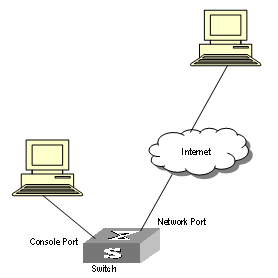
Figure 2-2 Network diagram for address table management configuration
III. Configuration procedure
# Enter the system view of the switch.
<H3C> system-view
# Add a MAC address (specify the native VLAN, port and state).
[H3C] mac-address static 00e0-fc35-dc71 interface ethernet2/1/2 vlan 1
# Set the address aging time to 500s.
[H3C] mac-address timer 500
# Display the MAC address configurations in any view.
[H3C] display mac-address interface ethernet2/1/2
MAC ADDR VLAN ID STATE PORT INDEX AGING TIME(s)
00-e0-fc-35-dc-71 1 Static Ethernet2/1/2 NOAGED
00-e0-fc-17-a7-d6 1 Learned Ethernet2/1/2 500
00-e0-fc-5e-b1-fb 1 Learned Ethernet2/1/2 500
00-e0-fc-55-f1-16 1 Learned Ethernet2/1/2 500
--- 4 mac address(es) found on port Ethernet2/1/2 ---
Chapter 3 Device management
3.1 Device Management Overview
With the device management function, the Ethernet Switch can display the current running state and event debugging information about the slots, thereby implementing the maintenance and management of the state and communication of the physical devices. In addition, there is a command available for rebooting the system, when some function failure occurs.
3.2 Device Management Configuration
The main device management tasks are to check the status of the boards, CPU, and the memory usage of the switch.
The following sections describe the configuration tasks for device management:
l Rebooting the Ethernet Switch
l Enabling the Timing Reboot Function
l Specifying the Bootstrap Programs for the Routing Switch
l Setting Slot Temperature Limit
l Updating Service Processing Boards
3.2.1 Rebooting the Ethernet Switch
It would be necessary for users to reboot the Ethernet switch when failure occurs.
Perform the following configuration in user view.
Table 3-1 Reboot Ethernet switch
|
Operation |
Command |
|
Root Ethernet switch |
reboot [ slot slot-no ] |
3.2.2 Enabling the Timing Reboot Function
After you enable the timing reboot function on the switch, the switch will be rebooted on the specified time.
Perform the following configuration in user view, and display schedule reboot command can be performed in any view.
Table 3-2 Enable the Timing Reboot Function
|
Operation |
Command |
|
Enable the timing reboot function of the switch, and set specified time and date |
schedule reboot at hh:mm [ yyyy/mm/dd ] |
|
Enable the timing reboot function of the switch, and set waiting time |
schedule reboot delay { hhh:mm | mmm } |
|
Cancel the parameter configuration of timing reboot function of the switch |
undo schedule reboot |
|
Check the parameter configuration of the reboot terminal service of the current switch |
display schedule reboot |
& Note:
The precision of switch timer is 1 minute. The switch will reboot in one minute when time comes to the specified rebooting point.
3.2.3 Specifying the Bootstrap Programs for the Routing Switch
You can specify two bootstrap programs for both active and standby SRPCs of the routing switch, with one used as the primary program and the other as the backup program. You can use the following command to specify the bootstrap programs for the routing switch:
Table 3-3 Specify a bootstrap program for the switch
|
Operation |
Command |
Description |
|
Specify the bootstrap program for the switch |
boot boot-loader { primary | backup } file-url [ slot slot-number ] |
Execute this command in user view. |
If the switch fails to boot up through the specified bootstrap program, it retries to boot up by using a program in the flash memory or the CF card. If it fails again, the switch fails to start.
The switch select one application program as bootstrap program from Flash or CF card according to the different values of flag BootDev. The detail is as follows:
l There are two primary bootstrap programs: one is in the Flash card (assume it is A); the other is in the CF card (assume it is B).
l There are two backup programs too: one is in the Flash card (assume it is C); the other is in the CF card (assume it is D).
l There is one flag BootDev.
You can view or modify the names of the bootstrap programs and enable equipment flag BootDev.
The detailed rules that the switch follows in selecting a bootstrap program are as follows in Table 3-4.
Table 3-4 The sequence of bootstrap program selection by the switch
|
BootDev Value of for boot from primary bootstrap program |
BootDev value for boot from backup bootstrap program |
Bootstrap program selection sequence |
|
0 |
0 |
A, C, B, D |
|
0 |
1 |
A, D, B, C |
|
1 |
1 |
B, D, A, C |
|
1 |
0 |
B, C, A, D |
& Note:
The H3C S9500 series routing switches (hereinafter referred to as S9500 series) support master/slave SRPU switchover. The two boards both have a program system. The program user can operate the programs on both boards. When you specify the bootstrap APP program for use by the slave board at the next startup, make sure that the URL of the program starts with “slot[No.]#[flash: | cf:]/”, where [No.] is the slave board number, and [flash: | cf:] is the name of the equipment, which can be a flash card of CR card. For example, if the slave board is on slot 1, the URL of 9500.app program on the slave board is “slot1#flash:/9500.app”.
3.2.4 Upgrading BootROM
You can use followed command to upgrade the BootROM with the BootROM program in the Flash Memory. This configuration task facilitates the remote upgrade. You can upload the BootROM program file from a remote end to the switch by FTP and then use this command to upgrade the BootROM.
Perform the following configuration in user view.
|
Operation |
Command |
|
Upgrade BootROM |
boot bootrom file-url slot slot-num-list |
3.2.5 Setting Slot Temperature Limit
The switch system alarms when the temperature on a slot exceeds the preset limit.
Perform the following configuration in user view.
Table 3-6 Set slot temperature limit
|
Operation |
Command |
|
Set slot temperature limit |
temperature-limit slot down-value up-value |
|
Restore temperature limit to default value |
undo temperature-limit slot |
3.2.6 Updating Service Processing Boards
The size of the flash for a main control board in a S9500 series routing switch is 16MB, while the size of current host software including the host application of service processing board reaches over 15MB. If a compact flash (CF) card is not configured, the current flash cannot provide enough room to save loading files. Therefore for the S9500 series routing switch with the main control board of a 16MB flash, the service processing board cannot be updated according to the original procedure. To update it, you need to execute the following command to download host software containing the app file of service processing board host application to the system’s synchronous dynamic random access memory (SDRAM).
& Note:
If you configure a CF card or the flash room of a subsequent main control board expands to 64MB, you need not to change the method to update boards. Then when loading files you only need to choose the APP files containing the application file of service processing board to update common interface boards and service processing boards.
Perform the following configuration in system view.
Table 3-7 Update service processing boards
|
Operation |
Command |
|
Download the host software of service processing board to the system memory |
update l3plus slot slot-no filename file-name ftpserver server-name username user-name password password [ port port-num ] |
3.3 Displaying and Debugging Device Management
Table 3-8 Display and Debug device management
|
Operation |
Command |
|
Display the module types and running states of each card. |
display device [ detail | [ shelf shelf-no ] [ frame frame-no ] [ slot slot-no ] ] |
|
Display the application deployed on next startup |
display boot-loader |
|
Display the running state of the built-in fans. |
display fan [ fan-id ] |
|
Display the Used status of switch memory |
display memory [ slot slot-no ] |
|
Display the state of the power. |
display power [ power-ID ] |
|
Display CPU occupancy |
display cpu [slot slot-no ] |
3.4 Device Management Configuration Example
3.4.1 Using the Switch as an FTP Client to Implement the Remote Upgrade (S9505 as example)
I. Network requirements
The user logs into the switch using Telnet, downloads the application from the FTP server to the flash memory of the switch, and implements remote upgrade using the right commands.
The switch serves as an FTP client and the remote PC as an FTP server. The configuration on the FTP server is as follows: an FTP user is configured with the name switch, the password hello and the read & write authority over the Switch root directory on the PC. The IP address of a VLAN interface on the switch is 1.1.1.1, and the IP address of the PC is 2.2.2.2. The switch and PC are reachable with each other.
The switch applications switch.app and boot.app are stored on the PC. Using FTP, these files can be downloaded from the remote FTP server to the switch.
II. Network diagram
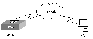
Figure 3-1 Network diagram for FTP configuration
III. Configuration procedure
1) Configure FTP server parameters on the PC: a user named as switch, password hello, read & write authority over the Switch directory on the PC. No further details are provided here
2) Configure the switch
# The switch has been configured with a Telnet user named as user, as 3-level user, with password hello, requiring username and password authentication.
# Use the telnet command to log into the switch.
<H3C>
![]() Caution:
Caution:
If the Flash Memory of the switch is not enough, you need to first delete the existing programs in the flash memory and then download the new ones to the memory.
# Enter the corresponding command in user view to establish FTP connection. Then enter correct username and password to log into the FTP server.
<H3C> ftp 2.2.2.2
Trying ...
Press CTRL+K to abort
Connected.
220 WFTPD 2.0 service (by Texas Imperial Software) ready for new user
User(none):switch
331 Give me your password, please
Password:*****
230 Logged in successfully
[ftp]
# Use the get command to download the switch.app and boot.app files from the FTP server to the flash directory on the FTP client.
[ftp] get switch.app
[ftp] get boot.app
# Use the quit command to release FTP connection and return to user view.
[ftp] quit
<H3C>
# Upgrade the BootROM of main board 0.
<H3C> boot bootrom boot.app slot 0
# Use the boot boot-loader command to specify the downloaded program as the application at the next login and reboot the switch.
<H3C>boot boot-loader primary flash:/switch.app slot 0
<H3C>disp boot-loader
The primary app to boot of board 0 at the next time is: flash:/switch.app
The backup app to boot of board 0 at the next time is: flash:/switch.app
The app to boot of board 0 at this time is: flash:/switch.app
<H3C>
3.4.2 Use the Switch as an FTP Server to Implement the Remote Upgrade (S9505 as example)
I. Network requirements
The switch serves as an FTP server and the PC as an FTP client. The configuration on the FTP server is as follows: an FTP user is configured with the name switch, the password hello and the read & write authority over the root directory of the switch. The IP address of a VLAN interface on the switch is 1.1.1.1, and the IP address of the PC is 2.2.2.2. The switch and PC are reachable with each other.
The switch application switch.app is stored on the PC. Using FTP, this file can be uploaded from the PC to the switch remotely, and the configuration file config.txt on the switch can be downloaded to the PC as a backup.
II. Network diagram
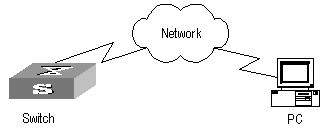
Figure 3-2 Network diagram for FTP configuration
III. Configuration procedure
1) Configure the switch
# Log into the switch through the console port locally or through telnet remotely (refer to the getting start module for details about the login modes).
<H3C>
# Enable FTP on the switch; configure a username, password and path.
[H3C] ftp server enable
[H3C] local-user switch
[H3C-luser-switch] service-type ftp ftp-directory flash:
[H3C-luser-switch] password simple hello
2) Run the FTP client program on the PC to set up an FTP connection with the switch. Then upload the switch program switch.app to the flash root directory on the switch and download the configuration file config.txt from the switch. The FTP client program is not provided along with the switch, so, it is for you to purchase and install it.
![]() Caution:
Caution:
If the Flash Memory on the switch is not sufficient, delete the original application program in the flash before uploading the new one into the flash of the switch.
3) After uploading, performs upgrading on the switch.
<H3C>
# You can use the boot boot-loader command to specify the new file as the application program on the next booting and reboot the switch to implement the upgrading of the application program.
<H3C> boot boot-loader primary flash:/switch.app slot 0
<H3C> reboot
Chapter 4 System Maintenance and Debugging
4.1 Basic System Configuration
The basic system configuration and management include:
l Switch name setting
l System clock setting
l Time zone setting
l Summer time setting
4.1.1 Setting a Name for a Switch
Perform the operation of sysname command in the system view.
Table 4-1 set a name for a Switch
|
Operation |
Command |
|
Set the switch name |
sysname sysname |
|
Restore the switch name to default value |
undo sysname |
4.1.2 Setting the System Clock
Perform the following configuration in user view.
Table 4-2 Set the system clock
|
Operation |
Command |
|
Set the system clock |
clock datetime HH:MM:SS YYYY/MM/DD |
4.1.3 Setting the Time Zone
You can configure the name of the local time zone and the time difference between the local time and the standard Universal Time Coordinated (UTC).
Perform the following configuration in user view.
|
Operation |
Command |
|
Set the local time |
clock timezone zone-name { add | minus } HH:MM:SS |
|
Restore to the default UTC time zone |
undo clock timezone |
By default, the UTC time zone is adopted.
4.1.4 Setting the Summer Time
You can set the name, starting and ending time of the summer time.
Perform the following configuration in user view.
|
Operation |
Command |
|
Set the name and range of the summer time |
clock summer-time zone-name { one-off | repeating } start-time start-date end-time end-date offset-time |
|
Remove the setting of the summer time |
undo clock summer-time |
By default, the summer time is not set.
4.2 Displaying the State and Information of the System
The switch provides the display command for displaying the system state and statistics information.
For the display commands related to each protocols and different ports, refer to the relevant chapters. The following display commands are used for displaying the system state and the statistics information.
Perform the following operations in any view.
Table 4-5 The display commands of the system
|
Operation |
Command |
|
Display the system clock |
display clock |
|
Display the system version |
display version |
|
Display the state of the debugging |
display debugging [ interface { interface- type interface-number ] [ module-name ] |
|
Display the information about the optical module connected with a in-place optical port on current frame |
display fiber-module or display fiber-module [ interface-type interface-number ] |
4.3 System Debugging
4.3.1 Enabling/Disabling the Terminal Debugging
The Ethernet switch provides various ways for debugging most of the supported protocols and functions, which can help you diagnose and address the errors.
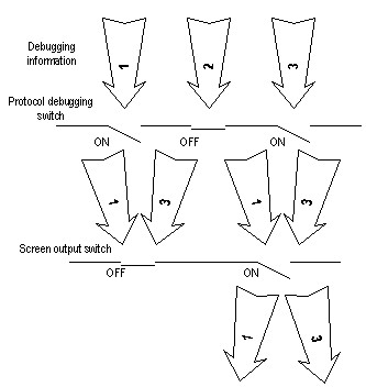
The following switches can control the outputs of the debugging information:
l Protocol debugging switch controls the debugging output of a protocol.
l Terminal debugging switch controls the debugging output on a specified user screen.
The figure below illustrates the relationship between two switches.
You can use the following commands to control the above-mentioned debugging.
Perform the following operations in user view.
Table 4-6 Enabling/Disabling the debugging
|
Operation |
Command |
|
Enable the protocol debugging |
debugging { all | timeout interval | module-name [ debugging-option ] } |
|
Disable the protocol debugging |
undo debugging { all | module-name [ debugging-option ] } |
|
Enable the terminal debugging |
terminal debugging |
|
Disable the terminal debugging |
undo terminal debugging |
For more about the usage and format of the debugging commands, refer to the relevant chapters.
& Note:
Since the debugging output will affect the system operating efficiency, do not enable the debugging without necessity, especially use the debugging all command with caution. When the debugging is over, disable all the debugging.
4.3.2 Displaying Diagnostic Information
When the Ethernet switch does not run well, you can collect all sorts of information about the switch to locate the source of fault. However, each module has its corresponding display command, you can use display diagnostic-information command.
You can perform the following operations in any view.
Table 4-7 displaying diagnostic information
|
Operation |
Command |
|
display diagnostic information |
display diagnostic-information |
& Note:
When using the display diagnostic-information command to keep track of Ethernet switch, you should execute the command at least twice so that you can compare the information for locating problem.
4.4 Testing Tools for Network Connection
4.4.1 ping
The ping command can be used to check the network connection and if the host is reachable.
Perform the following configuration in any view.
|
Operation |
Command |
|
Support IP ping |
ping [ ip ] [ -a ip-address | -c count | -d | - f | -h ttl | -i {interface-type interface-number } | -n | - p pattern | -q | -r | -s packetsize | -t timeout | -tos tos | -v | -vpn-instance vpn-instance-name ]* host |
The output of the command includes:
l The response to each ping message. If no response packet is received when time is out, ”Request time out” information appears. Otherwise, the data bytes, the packet sequence number, TTL, and the round-trip time of the response packet will be displayed.
l The final statistics, including the number of the packets the switch sent out and received, the packet loss ratio, the round-trip time in its minimum value, mean value and maximum value.
4.4.2 quick-ping enable
Use the quick-ping enable command to enable the ping distribution function.
Use the undo quick-ping enable command to disable the ping distribution function.
Perform the following configuration in system view.
Table 4-9 Enable/disable the PING distribution function
|
Operation |
Command |
|
Enable the PING distribution function |
quick-ping enable |
|
Disable the PING distribution function |
undo quick-ping enable |
By default, the PING distribution function is enabled.
4.4.3 tracert
The tracert is used for testing the gateways passed by the packets from the source host to the destination one. It is mainly used for checking if the network is connected and analyzing where the fault occurs in the network.
The execution process of the tracert command is described as follows: Send a packet with TTL value as 1 and the first hop sends back an ICMP error message indicating that the packet cannot be sent, for the TTL is timeout. Re-send the packet with TTL value as 2 and the second hop returns the TTL timeout message. The process is carried over and over until the packet reaches the destination. The purpose to carry out the process is to record the source address of each ICMP TTL timeout message, so as to provide the route of an IP packet to the destination.
Perform the following configuration in any view.
Table 4-10 The tracert command
|
Operation |
Command |
|
Trace route |
tracert [ -a source-IP | -f first-TTL | -m max-TTL | -p port | -q num-packet | -vpn-instance vpn-instance-name | -w timeout ] string |
4.5 Logging Function
4.5.1 Introduction to Info-center
The Info-center is an indispensable part of the Ethernet switch. It serves as an information center of the system software modules. The logging system is responsible for most of the information outputs, and it also makes detailed classification to filter the information efficiently. Coupled with the debugging program, the info-center provides powerful support for the network administrators and the R&D personnel to monitor the operating state of networks and diagnose network failures.
When the log information is output to terminal or log buffer, the following parts will be included:
% <priority> Timestamp Sysname Module name/Severity/Digest: Content
For example:
%Jun 7 05:22:03 2003 H3C IFNET/6/UPDOWN:Line protocol on interface Ethernet2/1/2, changed state to UP
When the log information is output to info-center, the first part will be “<Priority>”.
For example:
% <189>Jun 7 05:22:03 2003 H3C IFNET/6/UPDOWN:Line protocol on interface Ethernet0/0/0, changed state to UP
The description of the components of log information is as follows:
1) %
In practical output, some of the information is started with the % character, which means a logging is necessary.
2) Priority
The priority is computed according to following formula: facility*8+severity-1. The default value for the facility is 23. The range of severity is 1~8, and the severity will be introduced in separate section.
Priority is only effective when information is send to log host. There is no character between priority and timestamp.
3) Timestamp
If the logging information is send to the log host, the default format of timestamp is date
The date format of timestamp is " Mmm dd hh:mm:ss yyyy".
" Mmm " is month field, such as: Jan, Feb, Mar, Apr, May, Jun, Jul, Aug, Sep, Oct, Nov, Dec.
"dd" is day field, if the day is little than 10th, one blank should be added, such as " 7".
"hh:mm:ss" is time field, "hh" is from 00 to 23, "mm" and "ss" are from 00 to 59.
"yyyy" is year field.
4) Sysname
The sysname is the host name, the default value is "H3C".
User can change the host name through sysname command.
Notice: There is a blank between sysname and module name.
5) Module name
The module name is the name of module which create this logging information, the following sheet list some examples:
Table 4-11 The module name field
|
Module name |
Description |
|
8021X |
802.1X module |
|
ACL |
Access control list module |
|
ADBM |
MAC address management module |
|
ARP |
Address resolution protocol module |
|
BGP |
Border gateway protocol module |
|
CFM |
Configuration file management module |
|
CMD |
Command module |
|
default |
Default settings for all the modules |
|
DEV |
Device management module |
|
DHCP |
Dynamic host configuration protocol module |
|
DIAGCLI |
Diagnosis module |
|
DNS |
Domain name server module |
|
DRVMPLS |
Multiprotocol label switching drive module |
|
DRVL2 |
Layer 2 drive module |
|
DRVL3 |
Layer 3 drive module |
|
DRVL3MC |
Layer 3 multicast module |
|
MPLS |
MPLS drive module |
|
DRVPOS |
POS drive module |
|
DRVQACL |
QACL drive module |
|
DRVVPLS |
Virtual private LAN service drive module |
|
ETH |
Ethernet module |
|
FTPS |
FTP server module |
|
HA |
High availability module |
|
HABP |
Huawei authentication bypass protocol module |
|
HGMPS |
Huawei group management protocol service module |
|
HWCM |
Huawei configuration management MIB module |
|
IFNET |
Interface management module |
|
IGSP |
IGMP snooping module |
|
IP |
Internet protocol module |
|
ISIS |
Intermediate system-to-intermediate system intradomain routing protocol module |
|
L2INF |
L2 interface management module |
|
L2V |
L2 VPN module |
|
LACL |
LAN switch ACL module |
|
LDP |
Label distribution protocol module |
|
LINKAGG |
LINKAGG module |
|
LQOS |
LAN switch QoS module |
|
LS |
Local server module |
|
LSPAGENT |
Label switched path agent module |
|
LSPM |
Label switch path management module |
|
MIX |
Dual system management module |
|
MMC |
MMC module |
|
MODEM |
Modem module |
|
MPLSFW |
MPLS forward module |
|
MPM |
Multicast port management module |
|
MSDP |
Multicast source discovery protocol module |
|
MSTP |
Multiple spanning tree protocol module |
|
NAT |
Network address translation module |
|
NTP |
Network time protocol module |
|
OSPF |
Open shortest path first module |
|
PHY |
Physical sublayer & physical layer module |
|
POS_SNMP |
POS simple network management protocol module |
|
PPP |
Point to point protocol module |
|
PSSINIT |
PSSINIT module |
|
RDS |
RADIUS module |
|
RM |
Routing management module |
|
RMON |
Remote monitor module |
|
RPR |
Resilient packet ring module |
|
RSA |
RSA (Revest, Shamir and Adleman) encryption module |
|
RTPRO |
Routing protocol module |
|
SHELL |
User interface module |
|
SNMP |
Simple network management protocol module |
|
SOCKET |
Socket module |
|
SSH |
Secure shell module |
|
SYSM |
System manage veneer module |
|
SYSMIB |
System MIB module |
|
TAC |
Terminal access controller module |
|
TELNET |
Telnet module |
|
USERLOG |
User calling logging module |
|
VFS |
Virtual file system module |
|
VLAN |
Virtual local area network module |
|
VOS |
Virtual operate system module |
|
VRRP |
VRRP (virtual router redundancy protocol) module |
|
VTY |
VTY (virtual type terminal) module |
Notice: There is a slash ('/') between module name and severity.
6) Severity
Switch information falls into three categories: log information, debugging information and trap information. The info-center classifies every kind of information into 8 severity or urgent levels. The log filtering rule is that the system prohibits outputting the information whose severity level is greater than the set threshold. The more urgent the logging packet is, the smaller its severity level is. The level represented by “emergencies” is 1, and that represented by “debugging” is 8. Therefore, when the threshold of the severity level is “debugging”, the system will output all the information.
Definition of severity in logging information is as followed.
Table 4-12 Info-center-defined severity
|
Severity |
Value |
Description |
|
emergencies |
1 |
The extremely emergent errors |
|
alerts |
2 |
The errors that need to be corrected immediately. |
|
critical |
3 |
Critical errors |
|
errors |
4 |
The errors that need to be concerned but not critical |
|
warnings |
5 |
Warning, there might exist some kinds of errors. |
|
notifications |
6 |
The information should be concerned. |
|
informational |
7 |
Common prompting information |
|
debugging |
8 |
Debugging information |
Notice: There is a slash between severity and digest.
7) Digest
The digest is abbreviation, it represent the abstract of contents.
Notice: There is a colon between digest and content. The digest can be up to 32 characters long.
4.5.2 Info-center Configuration
Switch supports 7 output directions of information.
The system assigns a channel in each output direction by default. See the table below.
Table 4-13 Numbers and names of the channels for log output
|
Output direction |
Channel number |
Default channel name |
|
Console |
0 |
console |
|
Monitor |
1 |
monitor |
|
Info-center loghost |
2 |
loghost |
|
Trap buffer |
3 |
trapbuf |
|
Logging buffer |
4 |
logbuf |
|
snmp |
5 |
snmpagent |
|
Log file |
6 |
logfile |
& Note:
The settings in the 7 directions are independent from each other. The settings will take effect only after enabling the information center.
The info-center of Ethernet Switch has the following features:
l Support to output log in 7 directions, i.e., Console, monitor to Telnet terminal, logbuffer, loghost, trapbuffer, and SNMP log file.
l The log is divided into 8 levels according to the significance and it can be filtered based on the levels.
l The information can be classified in terms of the source modules and the information can be filtered in accordance with the modules.
l The output language can be selected between Chinese and English.
1) Sending the configuration information to the loghost
Table 4-14 Send the configuration information to the loghost
|
Device |
Configuration |
Default value |
Configuration description |
|
Switch |
Enable info-center |
By default, info-center is enabled |
Other configurations are valid only if the info-center is enabled |
|
Set the information output direction to the loghost |
- |
The configuration about the loghost on the switch and that on loghost must be the same; otherwise the information cannot be sent to the loghost correctly |
|
|
Set information source |
- |
You can define which modules and information to be sent out and the time-stamp format of information, and so on. You must turn on the switch of the corresponding module before defining output debugging information |
|
|
Loghost |
Refer to configuration cases for related log host configuration |
- |
- |
2) Sending the configuration information to the console terminal
Table 4-15 Send the configuration information to the console terminal.
|
Device |
Configuration |
Default value |
Configuration description |
|
Switch |
Enable info-center |
By default, info-center is enabled. |
Other configurations are valid only if the info-center is enabled |
|
Set the information output direction to the Console |
- |
- |
|
|
Set information source |
- |
You can define which modules and information to be sent out and the time-stamp format of information, and so on. You must turn on the switch of the corresponding module before defining output debugging information |
|
|
Enable terminal display function |
- |
You can view debugging information after enabling terminal display function |
3) Sending the configuration information to the monitor terminal
Table 4-16 Send the configuration information to the monitor terminal
|
Device |
Configuration |
Default value |
Configuration description |
|
Switch |
Enable info-center |
By default, info-center is enabled |
Other configurations are valid only if the info-center is enabled |
|
Set the information output direction to the monitor |
- |
- |
|
|
Set information source |
- |
You can define which modules and information to be sent out and the time-stamp format of information, and so on. You must turn on the switch of the corresponding module before defining output debugging information |
|
|
Enable the terminal display function and this function for the corresponding information |
- |
For Telnet terminal and dumb terminal, to view the information, you must enable the current terminal display function using the terminal monitor command |
4) Sending the configuration information to the log buffer
Table 4-17 Send the configuration information to the log buffer
|
Device |
Configuration |
Default value |
Configuration description |
|
Switch |
Enable info-center |
By default, info-center is enabled |
Other configurations are valid only if the info-center is enabled |
|
Set the information output direction to the logbuffer |
- |
You can configure the size of the log buffer at the same time. |
|
|
Set information source |
- |
You can define which modules and information to be sent out and the time-stamp format of information, and so on. You must turn on the switch of the corresponding module before defining output debugging information |
5) Sending the configuration information to the trap buffer
Table 4-18 Send the configuration information to the trap buffer
|
Device |
Configuration |
Default value |
Configuration description |
|
Switch |
Enable info-center |
By default, info-center is enabled |
Other configurations are valid only if the info-center is enabled |
|
Set the information output direction to the trapbuffer |
- |
You can configure the size of the trap buffer at the same time |
|
|
Set information source |
- |
You can define which modules and information to be sent out and the time-stamp format of information, and so on. You must turn on the switch of the corresponding module before defining output debugging information |
6) Sending the configuration information to SNMP
Table 4-19 Send the configuration information to SNMP
|
Device |
Configuration |
Default value |
Configuration description |
|
Switch |
Enable info-center |
By default, info-center is enabled |
Other configurations are valid only if the info-center is enabled |
|
Set the information output direction to SNMP |
- |
- |
|
|
Set information source |
- |
You can define which modules and information to be sent out and the time-stamp format of information, and so on. You must turn on the switch of the corresponding module before defining output debugging information |
|
|
Configure SNMP features |
- |
Refer to Chapter 5 SNMP Configuration |
|
|
Network management workstation |
The same as the SNMP configuration of the switch |
- |
- |
4.5.3 Sending the Configuration Information to the Loghost
To send configuration information to the loghost, follow the steps below:
1) Enabling info-center
Perform the following configuration in system view.
Table 4-20 Enable/disable info-center
|
Operation |
Command |
|
Enable info-center |
info-center enable |
|
Disable info-center |
undo info-center enable |
& Note:
Info-center is enabled by default. After info-center is enabled, system performances are affected when the system processes much information because of information classification and outputting.
2) Configuring to output information to the loghost
Perform the following configuration in system view.
Table 4-21 Configure to output information to the loghost
|
Operation |
Command |
|
Output information to the loghost |
info-center loghost host-ip-addr [ channel { channel-number | channel-name } | facility local-number | language { chinese | english } ]* |
|
Cancel the configuration of outputting information to loghost |
undo info-center loghost host-ip-addr |
Note that the IP address of log host must be correct.
& Note:
Ensure to enter the correct IP address using the info-center loghost command to configure loghost IP address. If you enter a loopback address, the system prompts of invalid address appears.
3) Configuring information source on the switch
By this configuration, you can define the information that sent to console terminal is generated by which modules, information type, information level, and so on.
Perform the following configuration in system view.
Table 4-22 Define information source
|
Operation |
Command |
|
Define information source |
info-center source { modu-name | default } channel { channel-number | channel-name } [ debug { level severity | state state }* | log { level severity | state state }* | trap { level severity | state state }* ]* |
|
Cancel the configuration of information source |
undo info-center source { modu-name | default | all } channel { channel-number | channel-name } |
modu-name specifies the module name; default represents all the modules; all represents all the information filter configuration in channel channel-number except default; level refers to the severity levels; severity specifies the severity level of information. The information with the level below it will not be output. channel-number specifies the channel number and channel-name specifies the channel name.
When defining the information sent to the loghost, channel-number or channel-name must be set to the channel that corresponds to loghost direction.
Every channel has been set with a default record, whose module name is default and the module number is 0xffff0000. However, for different channels, the default record may have different default settings of log, trap and debugging. When there is no specific configuration record for a module in the channel, use the default one.
& Note:
If you want to view the debugging information of some modules on the switch, you must select debugging as the information type when configuring information source, meantime using the debugging command to turn on the debugging switch of those modules.
4) Configuring the loghost
The configuration on the loghost must be the same with that on the switch. For related configuration, see the configuration examples in the later part.
4.5.4 Sending the Configuration Information to Console terminal
To send configuration information to console terminal, follow the steps below:
1) Enabling info-center
Perform the following configuration in system view.
Table 4-23 Enable/disable info-center
|
Operation |
Command |
|
Enable info-center |
info-center enable |
|
Disable info-center |
undo info-center enable |
& Note:
Info-center is enabled by default. After info-center is enabled, system performances are affected when the system processes much information because of information classification and outputting.
2) Configuring to output information to console terminal
Perform the following configuration in system view.
Table 4-24 Configure to output information to console terminal
|
Operation |
Command |
|
Output information to Console |
info-center console channel { channel-number | channel-name } |
|
Cancel the configuration of outputting information to Console |
undo info-center console channel |
3) Configuring information source on the switch
By this configuration, you can define the information that sent to console terminal is generated by which modules, information type, information level, and so on.
Perform the following configuration in system view:
Table 4-25 Define information source
|
Operation |
Command |
|
Define information source |
info-center source { modu-name | default } channel { channel-number | channel-name } [ debug { level severity | state state }* | log { level severity | state state }* | trap { level severity | state state }* ]* |
|
Cancel the configuration of information source |
undo info-center source { modu-name | default | all } channel { channel-number | channel-name } |
modu-name specifies the module name; default represents all the modules; all represents all the information filter configuration in channel channel-number except default; level refers to the severity levels; severity specifies the severity level of information. The information with the level below it will not be output. channel-number specifies the channel number and channel-name specifies the channel name.
When defining the information sent to the console terminal, channel-number or channel-name must be set to the channel that corresponds to Console direction.
Every channel has been set with a default record, whose module name is default and the module number is 0xffff0000. However, for different channels, the default record may have different default settings of log, trap and debugging. When there is no specific configuration record for a module in the channel, use the default one.
& Note:
If you want to view the debugging information of some modules on the switch, you must select debugging as the information type when configuring information source, meantime using the debugging command to turn on the debugging switch of those modules.
You can use the following commands to configure log information, debugging information and the time-stamp output format of trap information.
This configuration will affect the timestamp of the displayed information.
Perform the following configuration in system view:
Table 4-26 Configure the output format of time-stamp
|
Operation |
Command |
|
Configure the output format of the time-stamp |
info-center timestamp { log | trap | debugging } { boot | date | none } |
|
Output time-stamp is disabled |
undo info-center timestamp { log | trap | debugging } |
4) Enable terminal display function
To view the output information at the console terminal, you must first enable the corresponding log, debugging and trap information functions at the switch.
For example, if you have set the log information as the information sent to the console terminal, now you need to use the terminal logging command to enable the terminal display function of log information on the switch, then you can view the information at the console terminal.
Perform the following configuration in user view:
Table 4-27 Enable terminal display function
|
Operation |
Command |
|
Enable terminal display function of debugging information |
terminal debugging |
|
Disable terminal display function of debugging information |
undo terminal debugging |
|
Enable terminal display function of log information |
terminal logging |
|
Disable terminal display function of log information |
undo terminal logging |
|
Enable terminal display function of trap information |
terminal trapping |
|
Disable terminal display function of trap information |
undo terminal trapping |
4.5.5 Sending the Configuration Information to Telnet Terminal or Dumb Terminal
To send configuration information to Telnet terminal or dumb terminal, follow the steps below:
1) Enabling info-center
Perform the following configuration in system view.
Table 4-28 Enable/disable Info-center
|
Operation |
Command |
|
Enable info-center |
info-center enable |
|
Disable info-center |
undo info-center enable |
& Note:
Info-center is enabled by default. After info-center is enabled, system performances are affected when the system processes much information because of information classification and outputting.
2) Configuring to output information to Telnet terminal or dumb terminal
Perform the following configuration in system view.
Table 4-29 Configure to output information to Telnet terminal or dumb terminal
|
Operation |
Command |
|
Output information to Telnet terminal or dumb terminal |
info-center monitor channel { channel-number | channel-name } |
|
Cancel the configuration of outputting information to Telnet terminal or dumb terminal |
undo info-center monitor channel |
3) Configuring information source on the switch
By this configuration, you can define the information that sent to Telnet terminal or dumb terminal is generated by which modules, information type, information level, and so on.
Perform the following configuration in system view:
Table 4-30 Define information source
|
Operation |
Command |
|
Define information source |
info-center source { modu-name | default } channel { channel-number | channel-name } [ debug { level severity | state state }* | log { level severity | state state }* | trap { level severity | state state }* ]* |
|
Cancel the configuration of information source |
undo info-center source { modu-name | default | all } channel { channel-number | channel-name } |
modu-name specifies the module name; default represents all the modules; all represents all the information filter configuration in channel channel-number except default; level refers to the severity levels; severity specifies the severity level of information. The information with the level below it will not be output. channel-number specifies the channel number and channel-name specifies the channel name.
When defining the information sent to Telnet terminal or dumb terminal, channel-number or channel-name must be set to the channel that corresponds to monitor direction.
Every channel has been set with a default record, whose module name is default and the module number is 0xffff0000. However, for different channels, the default record may have different default settings of log, trap and debugging. When there is no specific configuration record for a module in the channel, use the default one.
& Note:
When there are more than one Telnet users or monitor users at the same time, some configuration parameters should be shared among the users, such as module-based filtering settings and severity threshold. When a user modifies these settings, it will be reflected on other clients.
& Note:
If you want to view the debugging information of some modules on the switch, you must select debugging as the information type when configuring information source, meantime using the debugging command to turn on the debugging switch of those modules.
You can use the following commands to configure log information, debugging information and the time-stamp output format of trap information.
This configuration will affect the timestamp of the displayed information.
Perform the following configuration in system view:
Table 4-31 Configure the output format of time-stamp
|
Operation |
Command |
|
Configure the output format of the time-stamp |
info-center timestamp { log | trap | debugging } { boot | date | none } |
|
Output time-stamp is disabled |
undo info-center timestamp { log | trap | debugging } |
4) Enabling terminal display function
To view the output information at the Telnet terminal or dumb terminal, you must first enable the terminal display function, and then the corresponding terminal display function of log information on the switch.
For example, if you have set the log information as the information sent to the Telnet terminal or dumb terminal, now you need to use the terminal monitor command to enable the terminal display function and the terminal logging command to enable the terminal display function of log information on the switch, then you can view the information at the Telnet terminal or dumb terminal.
Perform the following configuration in user view:
Table 4-32 Enable terminal display function
|
Operation |
Command |
|
Enable terminal display function of log, debugging and trap information |
terminal monitor |
|
Disable terminal display function of the above information |
undo terminal monitor |
|
Enable terminal display function of debugging information |
terminal debugging |
|
Disable terminal display function of debugging information |
undo terminal debugging |
|
Enable terminal display function of log information |
terminal logging |
|
Disable terminal display function of log information |
undo terminal logging |
|
Enable terminal display function of trap information |
terminal trapping |
|
Disable terminal display function of trap information |
undo terminal trapping |
4.5.6 Sending the Configuration Information to the Log Buffer
To send configuration information to the log buffer, follow the steps below:
1) Enabling info-center
Perform the following configuration in system view.
Table 4-33 Enable/disable info-center
|
Operation |
Command |
|
Enable info-center |
info-center enable |
|
Disable info-center |
undo info-center enable |
& Note:
Info-center is enabled by default. After info-center is enabled, system performances are affected when the system processes much information because of information classification and outputting.
2) Configuring to output information to the log buffer
Perform the following configuration in system view.
Table 4-34 Configure to output information to log buffer
|
Operation |
Command |
|
Output information to log buffer |
info-center logbuffer [ channel { channel-number | channel-name } | size buffersize ]* |
|
Cancel the configuration of outputting information to log buffer |
undo info-center logbuffer [ channel | size ] |
By default, the switch outputs information to the log buffer in the CPU. The size of the log buffer is 512.
3) Configuring information source on the switch
By this configuration, you can define the information that sent to log buffer is generated by which modules, information type, information level, and so on.
Perform the following configuration in system view:
Table 4-35 Define information source
|
Operation |
Command |
|
Define information source |
info-center source { modu-name | default } channel { channel-number | channel-name } [ debug { level severity | state state }* | log { level severity | state state }* | trap { level severity | state state }* ]* |
|
Cancel the configuration of information source |
undo info-center source { modu-name | default | all } channel { channel-number | channel-name } |
modu-name specifies the module name; default represents all the modules; all represents all the information filter configuration in channel channel-number except default; level refers to the severity levels; severity specifies the severity level of information. The information with the level below it will not be output. channel-number specifies the channel number and channel-name specifies the channel name.
When defining the information sent to log buffer, channel-number or channel-name must be set to the channel that corresponds to logbuffer direction.
Every channel has been set with a default record, whose module name is default and the module number is 0xffff0000. However, for different channels, the default record may have different default settings of log, trap and debugging. When there is no specific configuration record for a module in the channel, use the default one.
& Note:
If you want to view the debugging information of some modules on the switch, you must select debugging as the information type when configuring information source, meantime using the debugging command to turn on the debugging switch of those modules.
You can use the following commands to configure log information, debugging information and the time-stamp output format of trap information.
Perform the following configuration in system view:
Table 4-36 Configure the output format of time-stamp
|
Operation |
Command |
|
Configure the output format of the time-stamp |
info-center timestamp { log | trap | debugging } { boot | date | none } |
|
Output time-stamp is disabled |
undo info-center timestamp { log | trap | debugging } |
4.5.7 Sending the Configuration Information to the Trap Buffer
To send configuration information to the trap buffer, follow the steps below:
1) Enabling info-center
Perform the following configuration in system view.
Table 4-37 Enable/disable info-center
|
Operation |
Command |
|
Enable info-center |
info-center enable |
|
Disable info-center |
undo info-center enable |
& Note:
Info-center is enabled by default. After info-center is enabled, system performances are affected when the system processes much information because of information classification and outputting.
2) Configuring to output information to the trap buffer
Perform the following configuration in system view.
Table 4-38 Configure to output information to trap buffer
|
Operation |
Command |
|
Output information to trap buffer |
info-center trapbuffer [ size buffersize | channel { channel-number | channel-name } ]* |
|
Cancel the configuration of outputting information to trap buffer |
undo info-center trapbuffer [ channel | size ] |
By default, the switch outputs information to the trap buffer in the CPU. The size of the trap buffer is 256.
3) Configuring information source on the switch
By this configuration, you can define the information that sent to trap buffer is generated by which modules, information type, information level, and so on.
Perform the following configuration in system view:
Table 4-39 Define information source
|
Operation |
Command |
|
Define information source |
info-center source { modu-name | default } channel { channel-number | channel-name } [ debug { level severity | state state }* | log { level severity | state state }* | trap { level severity | state state }* ]* |
|
Cancel the configuration of information source |
undo info-center source { modu-name | default | all } channel { channel-number | channel-name } |
modu-name specifies the module name; default represents all the modules; all represents all the information filter configuration in channel channel-number except default; level refers to the severity levels; severity specifies the severity level of information. The information with the level below it will not be output. channel-number specifies the channel number and channel-name specifies the channel name.
When defining the information sent to trap buffer, channel-number or channel-name must be set to the channel that corresponds to trapbuffer direction.
Every channel has been set with a default record, whose module name is default and the module number is 0xffff0000. However, for different channels, the default record may have different default settings of log, trap and debugging. When there is no specific configuration record for a module in the channel, use the default one.
& Note:
If you want to view the debugging information of some modules on the switch, you must select debugging as the information type when configuring information source, meantime using the debugging command to turn on the debugging switch of those modules.
You can use the following commands to configure log information, debugging information and the time-stamp output format of trap information.
This configuration will affect the timestamp of the displayed information.
Perform the following configuration in system view:
Table 4-40 Configuring the output format of time-stamp
|
Operation |
Command |
|
Configure the output format of the time-stamp |
info-center timestamp { log | trap | debugging } { boot | date | none } |
|
Output time-stamp is disabled |
undo info-center timestamp { log | trap | debugging } |
4.5.8 Sending the Configuration Information to SNMP Network Management
To send configuration information to SNMP NM, follow the steps below:
1) Enabling info-center
Perform the following configuration in system view.
Table 4-41 Enable/disable info-center
|
Operation |
Command |
|
Enable info-center |
info-center enable |
|
Disable info-center |
undo info-center enable |
& Note:
Info-center is enabled by default. After info-center is enabled, system performances are affected when the system processes much information because of information classification and outputting.
2) Configuring to output information to SNMP NM
Perform the following configuration in system view.
Table 4-42 Configure to output information to SNMP NM
|
Operation |
Command |
|
Output information to SNMP NM |
info-center snmp channel { channel-number | channel-name } |
|
Cancel the configuration of outputting information to SNMP NM |
undo info-center snmp channel |
3) Configuring information source on the switch
By this configuration, you can define the information that sent to SNMP NM is generated by which modules, information type, information level, and so on.
Perform the following configuration in system view:
Table 4-43 Define information source
|
Operation |
Command |
|
Define information source |
info-center source { modu-name | default } channel { channel-number | channel-name } [ debug { level severity | state state }* | log { level severity | state state }* | trap { level severity | state state }* ]* |
|
Cancel the configuration of information source |
undo info-center source { modu-name | default | all } channel { channel-number | channel-name } |
modu-name specifies the module name; default represents all the modules; all represents all the information filter configuration in channel channel-number except default level refers to the severity levels; severity specifies the severity level of information. The information with the level below it will not be output. channel-number specifies the channel number and channel-name specifies the channel name.
When defining the information sent to SNMP NM, channel-number or channel-name must be set to the channel that corresponds to SNMP direction.
Every channel has been set with a default record, whose module name is default and the module number is 0xffff0000. However, for different channels, the default record may have different default settings of log, trap and debugging. When there is no specific configuration record for a module in the channel, use the default one.
& Note:
If you want to view the debugging information of some modules on the switch, you must select debugging as the information type when configuring information source, meantime using the debugging command to turn on the debugging switch of those modules.
You can use the following commands to configure log information, debugging information and the time-stamp output format of trap information.
This configuration will affect the timestamp of the displayed information.
Perform the following configuration in system view:
Table 4-44 Configure the output format of time-stamp
|
Operation |
Command |
|
Configure the output format of the time-stamp |
info-center timestamp { log | trap | debugging } { boot | date | none } |
|
Output time-stamp is disabled |
undo info-center timestamp { log | trap | debugging } |
4) Configuring of SNMP and network management workstation on the switch
You have to configure SNMP on the switch and the remote workstation to ensure that the information is correctly sent to SNMP NM. Then you can get correct information from network management workstation. SNMP configuration on switch refers to Chapter 5 SNMP Configuration.
4.5.9 Displaying and Debugging Info-center
After the above configuration, execute the display command in any view to view the running state of the info-center. You also can authenticate the effect of the configuration by viewing displayed information. Execute the reset command in user view to clear statistics of info-center.
Perform the following configuration in user view. The display command still can be performed in any view.
Table 4-45 Display and debug info-center
|
Operation |
Command |
|
Display the content of information channel |
display channel [ channel-number | channel-name ] |
|
Display configuration of system log and memory buffer |
display info-center |
|
Display the attribute of logbuffer and the information recorded in logbuffer |
display logbuffer [ summary ] [ level [ levelnum | emergencies | alerts | critical | debugging | errors | informational | notifications | warnings ] ] [ | [ begin | exclude | include text ] [ size sizenum ] |
|
Display the summary information recorded in logbuffer |
display logbuffer summary [ level severity ] |
|
Display the attribute of trapbuffer and the information recorded in trapbuffer |
display trapbuffer [ summary ] [ level [ levelnum | emergencies | alerts | critical | debugging | errors | informational | notifications | warnings ] ] [ size sizenum] |
|
Clear information in memory buffer |
reset logbuffer |
|
Clear information in trap buffer |
reset trapbuffer |
4.5.10 Configuration Examples of Sending Log to the Unix Loghost
I. Network requirements
The network requirements are as follows:
l Sending the log information of the switch to UNIX loghost
l The IP address of the loghost is 202.38.1.10
l The information with the severity level above informational will be sent to the loghost
l The output language is English
l The modules that allowed to output information are ARP and IP
II. Network diagram
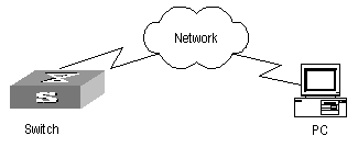
III. Configuration steps
1) Configuration on the switch
# Enable info-center
[H3C] info-center enable
# Set the host with the IP address of 202.38.1.10 as the loghost; set the severity level threshold value as informational, set the output language to English; set that the modules which are allowed to output information are ARP and IP.
[H3C] info-center loghost 202.38.1.10 facility local4 language english
[H3C] info-center source arp channel loghost log level informational
[H3C] info-center source ip channel loghost log level informational
2) Configuration on the loghost
This configuration is performed on the loghost. The following example is performed on SunOS 4.0 and the operation on Unix operation system produced by other manufactures is generally the same to the operation on SunOS 4.0.
Step 1: Perform the following command as the super user (root).
# mkdir /var/log/H3C
# touch /var/log/H3C/information
Step 2: Edit file /etc/syslog.conf as the super user (root), add the following selector/actor pairs.
# H3C configuration messages
local4.info /var/log/H3C/information
& Note:
Note the following points when editing /etc/syslog.conf:
l The note must occupy a line and start with the character #.
l There must be a tab other than a space as the separator in selector/actor pairs.
l No redundant space after file name.
l The device name and the acceptant log information level specified in /etc/syslog.conf must be consistent with info-center loghost and info-center loghost a.b.c.d facility configured on the switch. Otherwise, the log information probably cannot be output to the loghost correctly.
Step 3: After the establishment of information (log file) and the revision of /etc/syslog.conf, you should send a HUP signal to syslogd (system daemon), through the following command, to make syslogd reread its configuration file /etc/syslog.conf.
# ps -ae | grep syslogd
147
# kill -HUP 147
After the above operation, the switch system can record information in related log files.
& Note:
To configure facility, severity, filter and the file syslog.conf synthetically, you can get classification in great detail and filter the information.
4.5.11 Configuration examples of sending log to Linux loghost
I. Network requirements
The Network requirements are as follows:
l Sending the log information of the switch to LINUX loghost
l The IP address of the loghost is 202.38.1.10
l The information with the severity level above informational will be sent to the loghost
l The output language is English
l All modules are allowed to output information
II. Network diagram
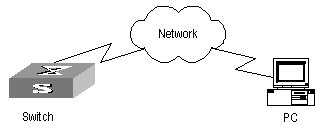
III. Configuration procedure
1) Configuration on the switch
# Enable info-center
[H3C] info-center enable
# Set the host with the IP address of 202.38.1.10 as the loghost; set the severity level threshold value as informational, set the output language to English; set all the modules are allowed output information.
[H3C] info-center loghost 202.38.1.10 facility local7 language english
[H3C] info-center source default channel loghost log level informational
2) Configuration on the loghost
This configuration is performed on the loghost.
Step 1: Perform the following command as the super user (root).
# mkdir /var/log/H3C
# touch /var/log/H3C/information
Step 2: Edit file /etc/syslog.conf as the super user (root), add the following selector/actor pairs.
# H3C configuration messages
local7.info /var/log/H3C/information
& Note:
Note the following points when editing /etc/syslog.conf:
l The note must occupy a line and start with the character #.
l There must be a tab other than a space as the separator in selector/actor pairs.
l No redundant space after file name.
l The device name and the acceptant log information level specified in /etc/syslog.conf must be consistent with info-center loghost and info-center loghost a.b.c.d facility configured on the switch. Otherwise, the log information probably cannot be output to the loghost correctly.
Step 3: After the establishment of information (log file) and the revision of /etc/syslog.conf, you should view the number of syslogd (system daemon) through the following command, kill syslogd daemon and reuse -r option the start syslogd in daemon.
# ps -ae | grep syslogd
147
# kill -9 147
# syslogd -r &
& Note:
For LINUX loghost, you must ensure that syslogd daemon is started by -r option.
After the above operation, the switch system can record information in related log files.
& Note:
To configure facility, severity, filter and the file syslog.conf synthetically, you can get classification in great detail and filter the information.
4.5.12 Configuration Examples of Sending Log to the Console Terminal
I. Network requirements
The network requirements are as follows:
l Sending the log information of the switch to console terminal
l The information with the severity level above informational will be sent to the console terminal
l The output language is English
The modules that allowed to output information are ARP and IP
II. Network diagram
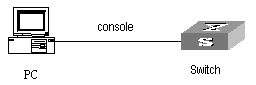
III. Configuration procedure
1) Configuration on the switch
# Enable info-center.
[H3C] info-center enable
# Configure console terminal log output; allow modules ARP and IP to output information; the severity level is restricted within the range of emergencies to informational.
[H3C] info-center console channel console
[H3C] info-center source arp channel console log level informational
[H3C] info-center source ip channel console log level informational
# Enable terminal display function.
<H3C> terminal logging
4.6 Configuring Clock Module
4.6.1 Introduction to Clock Module
The clock module is responsible for providing high-precision and high-reliability synchronous SDH link interface 38.88 MHz clock signals for all LPUs. The clock module selects an input clock source automatically, performs software phase-lock function, monitors the board status in real-time, accepts configurations delivered by the SRPU, responds to the query commands of the SRPU, and reports the card status changes and alarms.
4.6.2 Configuring Clock Module
Table 4-46 Configure clock module
|
Operation |
Command |
Description |
|
Enter system view |
system-view |
- |
|
Set the precedence of reference source |
clock { auto | manual source source } |
Optional |
|
Set SSM level |
clock ssm { dnu | lnc | prc | sets | tnc | unknown } source source |
Optional |
|
Set the time slot of Bits clock source |
clock sa-bit { sa4 | sa5 | sa6 | sa7 | sa8 } source source |
Optional |
|
Set SSM extraction flag |
clock forcessm { on | off } source source |
Optional |
|
Force the clock module to stop warming up the local oscillator |
clock stop warm-up |
Optional |
|
Set SSM to participate in control |
clock ssmcontrol { on | off } |
Optional |
|
Set the output port of line clock source |
clock lpuport slot slotid card cardid port portid |
Optional |
4.6.3 Displaying Clock Module
After the configurations above, you can use the display command in any view to view the running status of the clock module on the SRPU To verify the effect of the configuration by viewing the displayed information.
Table 4-47 Display and debug clock module on the SRPU
|
Operation |
Command |
|
Query detailed information on clock device |
display clock device |
|
Query version information of clock device |
display clock version |
|
Query D/A value of clock device |
display clock d/a |
|
Query base phase of clock device |
display clock basephase |
|
Query output port of clock source on LPU |
display clock lpuport |
|
Query the status of 18 clock sources |
display clock source |
|
Query the self test result of clock |
display clock self-test-result |
|
Query the priorities of 18 clock sources |
display clock priority |
|
Query SSM levels of 18 clock sources |
display clock ssm-level |
|
Query SSM output level of clock |
display clock ssm-output |
|
Query phase lock state of clock |
display clock phase-lock-state |
|
Query clock work mode |
display clock work-mode |
|
Query current configuration of clock module |
display clock config |
Chapter 5 SNMP Configuration
5.1 SNMP Overview
By far, the Simple Network Management Protocol (SNMP) has gained the most extensive application in the computer networks. SNMP has been put into use and widely accepted as an industry standard in practice. It is used for ensuring the transmission of the management information between any two nodes. In this way, network administrators can easily search and modify the information on any node on the network. In the meantime, they can locate faults promptly and implement the fault diagnosis, capacity planning and report generating. SNMP adopts the polling mechanism and provides the most basic function set. It is most applicable to the small-sized, fast-speed and low-cost environment. It only requires the unverified transport layer protocol UDP; and is thus widely supported by many other products.
In terms of structure, SNMP can be divided into two parts, namely, Network Management Station and Agent. Network Management Station is the workstation for running the client program. At present, the commonly used NM platforms include Sun NetManager and IBM NetView. Agent is the server software operated on network devices. Network Management Station can send GetRequest, GetNextRequest and SetRequest messages to the Agent. Upon receiving the requests from the Network Management Station, Agent will perform Read or Write operation according to the message types, generate and return the Response message to Network Management Station. On the other hand, Agent will send Trap message on its own initiative to the Network Management Station to report the events whenever the device encounters any abnormalities such as restart.
5.2 SNMP Versions and Supported MIB
To uniquely identify the management variables of a device in SNMP messages, SNMP adopts the hierarchical naming scheme to identify the managed objects. It is like a tree. A tree node represents a managed object, as shown in the figure below. Thus the object can be identified with the unique path starting from the root.
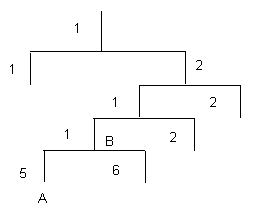
Figure 5-1 Architecture of the MIB tree
The MIB (Management Information Base) is used to describe the hierarchical architecture of the tree and it is the set defined by the standard variables of the monitored network device. In the above figure, the managed object B can be uniquely specified by a string of numbers {1.2.1.1}. The number string is the Object Identifier of the managed object.
The current SNMP Agent of Ethernet switch supports SNMP V1, V2C and V3. The MIBs supported are listed in the following table.
Table 5-1 MIBs supported by the Ethernet Switch
|
MIB attribute |
MIB content |
References |
|
Public MIB |
MIB II based on TCP/IP network device |
RFC1213 |
|
BRIDGE MIB |
RFC1493 |
|
|
RFC2675 |
||
|
RIP MIB |
RFC1724 |
|
|
RMON MIB |
RFC2819 |
|
|
Ethernet MIB |
RFC2665 |
|
|
OSPF MIB |
RFC1253 |
|
|
IF MIB |
RFC1573 |
|
|
Private MIB |
DHCP MIB |
- |
|
QACL MIB |
- |
|
|
ADBM MIB |
- |
|
|
RSTP MIB |
- |
|
|
VLAN MIB |
- |
|
|
Device management |
- |
|
|
Interface management |
- |
5.3 Configuring SNMP
The following sections describe the SNMP configuration tasks.
l Setting the System Information
l Enabling/Disabling SNMP Agent to Send Trap
l Setting the Destination Address of Trap
l Setting Lifetime of Trap Message
l Setting the Engine ID of a Local or Remote Device
l Setting/Deleting an SNMP Group
l Setting the Source Address of Trap
l Adding/Deleting a User to/from an SNMP Group
l Creating/Updating View Information or Deleting a View
l Setting the Size of the SNMP Packet Sent/Received by an Agent
5.3.1 Setting Community Names
l SNMP V1 and SNMPV2C adopt the community name authentication scheme. SNMP Community is named with a character string, which is called community name. SNMP community name defines the relationship between SNMP manager and SNMP agent. The community name functions like a password, that is, it controls the access of the SNMP manager to the SNMP agent. You can choose to specify one or more community name-related features: Define MIB views of all the accessible MIB subsets.
l Define the read-only or read-write access mode of the community name to the MIB. The community with read-only authority can only query the device information, whereas the community with read-write authority can also configure the device.
Perform the following configuration in system view.
|
Operation |
Command |
|
Set the community name and the access authority |
snmp-agent community { read | write } community-name [ [ mib-view-view-name ] [ acl acl-list ] ] |
|
Remove the community name and the access authority |
undo snmp-agent community community-name |
5.3.2 Setting the System Information
System information includes the ID and the contact method of the administrator, the location of the Ethernet switch and the version of the SNMP.
The ID and the contact method of the administrator is a character string describing the contact information used for the system maintenance. Through this information, the device maintenance staffs can obtain the manufacturer information of the device so as to contact the manufacturer in case the device is in trouble. You can use the following command to set the contact information.
The location information of the Ethernet switch is a management variable of the system group in MIB, which represents the location of the managed device.
Perform the following configuration in system view.
Table 5-3 Set the system information
|
Operation |
Command |
|
Set the system information |
snmp-agent sys-info { contact sysContact | location sysLocation | version { { v1 | v2c | v3 }* | all } } |
|
Restore the default information |
undo snmp-agent sys-info { { contact | location }* | version { { v1 | v2c | v3 }* | all } } |
By default, the contact information for system maintenance is "Hangzhou H3C Technologies Co., Ltd.", the physical location information is "Hangzhou ,China", and the version is SNMPv3
5.3.3 Enabling/Disabling SNMP Agent to Send Trap
The managed device transmits trap without request to the Network Management Station to report some critical and urgent events (such as restart).
You can use the following commands to enable or disable the managed device to send trap message.
Perform the following configuration in corresponding views.
Table 5-4 Enable/disable SNMP Agent to send Trap
By default, the current port or VLAN interface sends trap messages.
5.3.4 Setting the Destination Address of Trap
You can use the following commands to set or delete the destination address of the trap.
Perform the following configuration in system view.
Table 5-5 Set the destination address of trap
|
Operation |
Command |
|
Set the destination address of trap |
snmp-agent target-host trap address udp-domain host-addr [ udp-port udp-port-number ] params securityname securityname [ v1 | v2c | v3 [ authentication | privacy ] ] |
|
Delete the destination address of trap |
undo snmp-agent target-host host-addr securityname securityname |
5.3.5 Setting Lifetime of Trap Message
You can use the following command to set lifetime of Trap message. Trap message that exists longer than the set lifetime will be dropped.
Perform the following configuration in system view.
Table 5-6 Set the lifetime of Trap message
|
Operation |
Command |
|
Set lifetime of Trap message |
snmp-agent trap life seconds |
|
Restore lifetime of Trap message |
undo snmp-agent trap life |
By default, the lifetime of Trap message is 120 seconds.
5.3.6 Setting the Engine ID of a Local or Remote Device
You can use the following commands to set the engine ID of a local or remote device.
Perform the following configuration in system view.
Table 5-7 Set the engine ID of a local or remote device
|
Operation |
Command |
|
Set the engine ID of the device |
snmp-agent local-engineid engineid |
|
Restore the default engine ID of the device. |
undo snmp-agent local-engineid |
The engine ID of the device is in hexadecimal notation and has at least five characters, which can be IP address, MAC address or self-defined text. It defaults to the enterprise number + the device information.
5.3.7 Setting/Deleting an SNMP Group
You can use the following commands to set or delete an SNMP group.
Perform the following configuration in system view.
Table 5-8 Set/Delete an SNMP Group
|
Operation |
Command |
|
Set an SNMP group |
snmp-agent group { v1 | v2c } group-name [ read-view read-view ] [ write-view write-view ] [ notify-view notify-view ] [ acl acl-list ] snmp-agent group v3 group-name [ authentication | privacy ] [ read-view read-view ] [ write-view write-view ] [notify-view notify-view ] [ acl acl-list ] |
|
Delete an SNMP group |
undo snmp-agent group { v1 | v2c } group-name undo snmp-agent group v3 group-name [ authentication | privacy ] |
5.3.8 Setting the Source Address of Trap
You can use the following commands to set or remove the source address of the trap.
Perform the following configuration in system view.
Table 5-9 Set the source address of trap
|
Operation |
Command |
|
Set the Source Address of Trap |
snmp-agent trap source interface-type interface-number |
|
Remove the source address of trap |
undo snmp-agent trap source |
& Note:
Currently, this command takes effect only on the interfaces with vlan-interface type.
5.3.9 Adding/Deleting a User to/from an SNMP Group
You can use the following commands to add or delete a user to/from an SNMP group.
Perform the following configuration in system view.
Table 5-10 Add/Delete a user to/from an SNMP group
|
Operation |
Command |
|
Add a user to an SNMP group. |
snmp-agent usm-user { v1 | v2c } username groupname [ acl acl-list ] snmp-agent usm-user v3 username groupname [ authentication-mode { md5 | sha } authpassstring [ privacy-mode { des56 privpassstring } ] ] [ acl acl-list ] |
|
Delete a user from an SNMP group. |
undo snmp-agent usm-user { v1 | v2c } username groupname undo snmp-agent usm-user v3 username groupname { local | engineid engine-id } |
You must first configure the SNMP engine ID before configuring the remote user for an agent, because the engine ID is required during the authentication. If you forget to configure the engine ID before adding a user, the operation of adding this user will fail.
For SNMP V1 and V2c, this operation is adding a new community name, while for SNMP V3, this operation is adding a user for an SNMP group.
5.3.10 Creating/Updating View Information or Deleting a View
Perform the following configuration in system view.
Table 5-11 Create/Update view information or delete a view
|
Operation |
Command |
|
Create/Update view information |
snmp-agent mib-view { included | excluded } view-name oid-tree |
|
Delete a view |
undo snmp-agent mib-view view-name |
5.3.11 Setting the Size of the SNMP Packet Sent/Received by an Agent
You can use the following commands to set the size of SNMP packet sent/received by an agent.
Perform the following configuration in system view.
Table 5-12 Set the size of the SNMP packet sent/received by an agent
|
Operation |
Command |
|
Set the size of the SNMP packet sent/received by an agent |
snmp-agent packet max-size byte-count |
|
Restore the default size of the SNMP packet sent/received by an agent |
undo snmp-agent packet max-size |
The agent can receive/send the SNMP packets of the sizes ranging from 484 to 17940, measured in bytes. By default, the size of an SNMP packet is 1500 bytes.
5.3.12 Disabling SNMP Agent
To disable SNMP Agent, perform the following configuration in system view.
|
Operation |
Command |
|
Disable snmp agent |
undo snmp-agent |
If users disable NMP Agent, it will be enabled whatever snmp-agent command is configured thereafter.
5.4 Displaying and Debugging SNMP
After the above configuration, execute the display command in any view to display the running of the SNMP configuration, and to verify the effect of the configuration.
Table 5-14 Display and debug SNMP
|
Operation |
Command |
|
Display the statistics information about SNMP packets |
display snmp-agent statistics |
|
Display the engine ID of the active device |
display snmp-agent { local-engineid | remote-engineid } |
|
Display the group name, the security mode, the states for all types of views, and the storage mode of each group of the switch. |
display snmp-agent group [ group-name ] |
|
Display SNMP user information in the group user table |
display snmp-agent usm-user [ engineid engineid | group groupname | username username ]* |
|
Display the current community name |
display snmp-agent community [ read | write ] |
|
Display the current MIB view |
display snmp-agent mib-view [ exclude | include | { viewname mib-view } ] |
|
Display the contact character strings, location character strings, and the SNMP version of the system |
display snmp-agent sys-info [ contact | location | version ]* |
5.5 SNMP Configuration Example
I. Network requirements
Network Management Station and the Ethernet switch are connected through the Ethernet. The IP address of Network Management Station is 129.102.149.23 and that of the VLAN interface on the switch is 129.102.0.1. Perform the following configurations on the switch: setting the community name and access authority, administrator ID, contact and switch location, and enabling the switch to send trap packets.
II. Network diagram
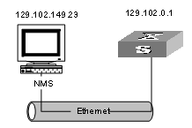
Figure 5-2 Network diagram for SNMP configuration
III. Configuration procedure
# Enter the system view.
<H3C> system-view
# Set the community name, group and user.
[H3C] snmp-agent sys-info version all
[H3C] snmp-agent community read public
[H3C] snmp-agent mib include internet 1.3.6.1
[H3C] snmp-agent group v3 managev3group write internet
[H3C] snmp-agent usm v3 managev3user managev3group
# Set the VLAN interface 2 as the interface for network management. Add port GigabitEthernet 2/1/3 to the VLAN 2. This port will be used for network management. Set the IP address of VLAN interface 2 as 129.102.0.1.
[H3C] vlan 2
[H3C-vlan2] port gigabitethernet 2/1/3
[H3C-vlan2] interface vlan 2
[H3C-Vlan-interface2] ip address 129.102.0.1 255.255.0.0
# Enable SNMP agent to send the trap to network management station whose IP address is 129.102.149.23. The SNMP community is public.
[H3C] snmp-agent trap enable standard authentication
[H3C] snmp-agent trap enable standard coldstart
[H3C] snmp-agent trap enable standard linkup
[H3C] snmp-agent trap enable standard linkdown
[H3C] snmp-agent target-host trap address udp-domain 129.102.149.23 udp-port 5000 params securityname public
IV. Configure network management system
The PC on which the network management resides requires for login configuration. As for Mib-Browser, the login configuration is as follows: SNMPV1/V2 logs in using the default community name public, and the SNMPV3 logs in using managev3user.
The Ethernet Switch supports iManager Quidview NMS. Users can query and configure the Ethernet switch through the network management system. For details, see the manuals for the network management products.
Chapter 6 RMON Configuration
6.1 RMON Overview
Remote Network Monitoring (RMON) is a type of IETF-defined MIB. It is the most important enhancement to the MIB II standard. It mainly used for monitoring the data traffic on a segment and even on a whole network. It is one of the widely used Network Management standards by far.
RMON is implemented fully based on the SNMP architecture (which is one of its outstanding advantages) and compatible with the existing SNMP framework, and therefore it is unnecessary to adjust the protocol. RMON includes NMS and the Agent running on the network devices. On the network monitor or detector, RMON Agent tracks and accounts different traffic information on the segment connected to its port, such as the total number of packets on a segment in a certain period of time or that of the correct packets sent to a host. ROMN helps the SNMP monitor the remote network device more actively and effectively, which provides a highly efficient means for the monitoring of the subnet operations. RMON can reduce the communication traffic between the NMS and the agent, thus facilitates an effective management over the large interconnected networks.
RMON allows multiple monitors. It can collect data in two ways.
l One is to collect data with a special RMON probe. NMS directly obtains the management information from the RMON probe and controls the network resource. In this way, it can obtain all the information of RMON MIB
l Another way is to implant the RMON Agent directly into the network devices (for example router, switch and HUB), so that the devices become network facilities with RMON probe function. RMON NMS uses the basic SNMP commands to exchange data information with SNMP Agent and collect NM information. However, limited by the device resources, normally, not all the data of RMON MIB can be obtained with this method. In most cases, only four groups of information can be collected. The four groups include alarm information, event information, history information and statistics information.
The Ethernet Switch implements RMON in the second method by far. With the RMON-supported SNMP Agent running on the network monitor, NMS can obtain such information as the overall traffic of the segment connected to the managed network device port, the error statistics and performance statistics, thereby implementing the management (generally remote management) over the network.
6.2 Configuring RMON
& Note:
Before configuring RMON, you must ensure that the SNMP agent is properly configured. See Chapter 8 SSH Terminal Service for the SNMP agent configuration.
The following sections describe the RMON configuration tasks.
l Adding/Deleting an Entry to/from the Event Table
l Adding/Deleting an Entry to/from the Alarm Table
l Adding/Deleting an Entry to/from the Extended RMON Alarm Table
l Adding/Deleting an Entry to/from the History Control Table
l Adding/Deleting an Entry to/from the Statistics Table
6.2.1 Adding/Deleting an Entry to/from the Event Table
RMON event management defines the event ID and the handling of the event.
You can handle the event in the following ways:
l Keeping logs
l Sending the trap messages to NMS
l Keeping logs and sending the trap messages to NMS
Perform the following configuration in system view.
Table 6-1 Add/delete an entry to/from the event table
|
Operation |
Command |
|
Add an entry to the event table |
rmon event event-entry [ description string ] { log | trap trap-community | log-trap log-trapcommunity | none } [ owner rmon-station ] |
|
Delete an entry from the event table |
undo rmon event event-entry |
6.2.2 Adding/Deleting an Entry to/from the Alarm Table
RMON alarm management can monitor the specified alarm variables such as the statistics on a port. When a value of the monitored data exceeds the defined threshold, an alarm event will be generated. And then the events are handled according to the definition, which is decided in the event management.
& Note:
Before adding an entry to the alarm table, you need to define the event referenced in the alarm table by using the rmon event command.
Perform the following configuration in system view.
Table 6-2 Add/delete an entry to/from the alarm table
|
Operation |
Command |
|
Add an entry to the alarm table |
rmon alarm entry-number alarm-variable sampling-time { delta | absolute } rising-threshold threshold-value1 event-entry1 falling-threshold threshold-value2 event-entry2 [ owner text ] |
|
Delete an entry from the alarm table |
undo rmon alarm entry-number |
After you defined the alarm entry, the system then processes the entry in the following way:
1) Sampling the defined alarm-variable according to the time interval sampling-time that you have set
2) Comparing the sampled value with the configured threshold and handling them in the way described in the following table
Table 6-3 Handling the alarm entry
|
Case |
Processing |
|
The sampled value is greater than the configured upper limit threshold-value1 |
The defined event event-entry1 is triggered |
|
The sampled value is less than the configured lower limit threshold-value2 |
The defined event event-entry2 is triggered |
6.2.3 Adding/Deleting an Entry to/from the Extended RMON Alarm Table
You can use the command to add/delete an entry to/from the extended RMON alarm table. The extended alarm entry performs mathematical operation to the sampled value of the alarm variable, and then the result will be compared with the configured threshold to implementing the alarm function.
& Note:
Before adding extended alarm entry, you need to define the referenced event in the extended alarm entry by using the rmon event command.
You can define up to 50 prialarm entries.
Perform the following configuration in system view.
Table 6-4 Add/delete an entry to/from the extended RMON alarm table
|
Operation |
Command |
|
Add an entry to the extended RMON alarm table |
rmon prialarm entry-number alarm-var [ alarm-des ] sampling-timer { delta | absolute | changeratio } rising-threshold threshold-value1 event-entry1 falling-threshold threshold-value2 event-entry2 entrytype { forever | cycle cycle-period } [ owner text ] |
|
Delete an entry from the extended RMON alarm table |
undo rmon prialarm entry-number |
After you define the extended alarm entry, the system processes the entry in the following way:
1) Sampling the defined prialarm-formula according to the time interval sampling-time that you have set
2) Performing the operation to the sampled value according to the defined formula prialarm-formula
3) Comparing the result with the configured threshold and handling them in the way described in the following table
Table 6-5 Handling the extended alarm entry
|
Case |
Processing |
|
The result is greater than the configured upper limit threshold-value1 |
The defined event event-entry1 is triggered |
|
The result is less than the configured lower limit threshold-value2 |
The defined event event-entry2 is triggered |
6.2.4 Adding/Deleting an Entry to/from the History Control Table
The history data management helps you set the history data collection, periodical data collection and storage of the specified ports. The sampling information includes the utilization ratio, error counts and total number of packets.
You can use the following commands to add/delete an entry to/from the history control table.
Perform the following configuration in Ethernet port view.
Table 6-6 Add/delete an entry to/from the history control table
|
Operation |
Command |
|
Add an entry to the history control table. |
rmon history entry-number buckets number interval sampling-interval [ owner text-string ] |
|
Delete an entry from the history control table. |
undo rmon history entry-number |
History control entry calculates various data at the sampling time interval. You can use the display rmon history command to view the information of the history control entry.
6.2.5 Adding/Deleting an Entry to/from the Statistics Table
The RMON statistics management concerns the port usage monitoring and error statistics when using the ports. The statistics include collision, CRC and queuing, undersize packets or oversize packets, timeout transmission, fragments, broadcast, multicast and unicast messages and the usage ratio of bandwidth.
You can use the following commands to add/delete an entry to/from the statistics table.
Perform the following configuration in Ethernet port view.
Table 6-7 Add/delete an entry to/from the statistics table
|
Operation |
Command |
|
Add an entry to the statistics table |
rmon statistics entry-number [ owner text-string ] |
|
Delete an entry from the statistics table |
undo rmon statistics entry-number |
6.3 Displaying and Debugging RMON
Table 6-8 Display and debug RMON
|
Operation |
Command |
|
Display the RMON statistics |
display rmon statistics [ port-num ] |
|
Display the history information of RMON |
display rmon history [ port-num ] |
|
Display the alarm information of RMON |
display rmon alarm [ alarm-table-entry ] |
|
Display the extended alarm information of RMON |
display rmon prialarm [ prialarm-table-entry ] |
|
Display the RMON event |
display rmon event [ event-table-entry ] |
|
Display the event log of RMON |
display rmon eventlog [ event-number ] |
6.4 RMON Configuration Example
I. Network requirements
Set an entry in RMON Ethernet statistics table for the Ethernet port performance, which is convenient for network administrators’ query.
II. Network diagram
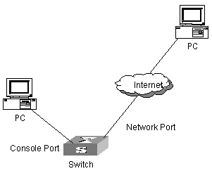
Figure 6-1 Network diagram for RMON configuration
III. Configuration procedure
# Configure RMON.
<H3C> system-view
System View: return to User View with Ctrl+Z.
[H3C]interface Ethernet 2/1/1
[H3C-Ethernet2/1/1] rmon statistics 1 owner H3C-rmon
# View the configurations in user view.
<H3C> display rmon statistics Ethernet 2/1/1
Statistics entry 1 owned by H3C-rmon is VALID.
Gathers statistics of interface Ethernet2/1/1. Received:
octets : 270149, packets : 1954
broadcast packets :1570 , multicast packets:365
undersized packets :0 , oversized packets:0
fragments packets :0 , jabbers packets :0
CRC alignment errors:0 , collisions :0
Dropped packet events (due to lack of resources):0
Packets received according to length (in octets):
64 :644 , 65-127 :518 , 128-255 :688
256-511:101 , 512-1023:3 , 1024-1518:0
# Configure an event before configuring alarm and prialarm.
[H3C]rmon event 1 log owner H3C-rmon
[H3C]display rmon event 1
Event table 1 owned by H3C-rmon is VALID.
Description: null.
Will cause log when triggered, last triggered at 1days 01h:42m:09s.
#Configure an alarm group.
[H3C]rmon alarm 1 1.3.6.1.2.1.16.1.1.1.4.1 10 delta rising_threshold 1000 1 falling_threshold 100 1 owner H3C-rmon
[H3C]dis rmon alarm 1
Alarm table 1 owned by H3C-rmon is VALID.
Samples type : delta
Variable formula : 1.3.6.1.2.1.16.1.1.1.4.1<etherStatsOctets.1>
Description : Ethernet2/1/1
Sampling interval : 10(sec)
Rising threshold : 1000(linked with event 1)
Falling threshold : 100(linked with event 1)
When startup enables : risingOrFallingAlarm
Latest value : 0
# Configure an extended alarm group.
[H3C]rmon prialarm 1 ((.1.3.6.1.4.1.2011.6.1.2.1.1.2.0-.1.3.6.1.4.1.2011.
6.1.2.1.1.3.0)*100/.1.3.6.1.4.1.2011.6.1.2.1.1.2.0) prialarm1 10 delta risi
ng_threshold 70 1 falling_threshold 50 1 entrytype forever
[H3C]display rmon prialarm 1
Prialarm table 1 owned by null is VALID.
Samples type : delta
Variable formula : ((.1.3.6.1.4.1.2011.6.1.2.1.1.2.0-.1.3.6.1.4.1.2011.6.1.2.1.1.
3.0)*100/.1.3.6.1.4.1.2011.6.1.2.1.1.2.0)
Description : prialarm1
Sampling interval : 10(sec)
Rising threshold : 70(linked with event 1)
Falling threshold : 50(linked with event 1)
When startup enables : risingOrFallingAlarm
This entry will exist : forever.
Latest value : 0
Note: The “0” in black means the memory of slot 0 is queried.
Chapter 7 NTP Configuration
7.1 Brief Introduction to NTP
7.1.1 NTP Functions
As the network topology gets more and more complex, it becomes important to synchronize the clocks of the equipment on the whole network. Network Time Protocol (NTP) is the TCP/IP that advertises the accurate time throughout the network.
NTP ensures the consistency of the following applications:
l For the increment backup between the backup server and client, NTP ensures the clock synchronization between the two systems.
l For multiple systems that coordinate to process a complex event, NTP ensures them to reference the same clock and guarantee the right order of the event.
l Guarantee the normal operation of the inter-system (Remote Procedure Call).
l Record for an application when a user logs in to a system, a file is modified, or some other operation is performed.
7.1.2 Basic Operating Principle of NTP
The following figure illustrates the basic operating principle of NTP:
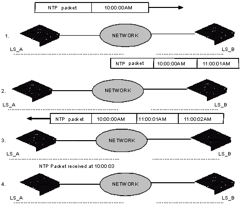
Figure 7-1 Basic operating principle of NTP
In the figure above, Ethernet Switch A and Ethernet Switch B are connected through the Ethernet port. They have independent system clocks. Before implement automatic clock synchronization on both switches, we assume that:
l Before synchronizing the system clocks on Ethernet Switch A and B, the clock on Ethernet Switch A is set to 10:00:00am, and that on B is set to 11:00:00am.
l Ethernet Switch B serves as an NTP time server. That is, Ethernet Switch A synchronizes the local clock with the clock of B.
l It takes 1 second to transmit a data packet from either A or B to the opposite end.
The system clocks are synchronized as follows:
l Ethernet Switch A sends an NTP packet to Ethernet Switch B. The packet carries the timestamp 10:00:00am (T1) that tells when it left Ethernet Switch A.
l When the NTP packet arrives at Ethernet Switch B, Ethernet Switch B adds a local timestamp 11:00:01am (T2) to it.
l When the NTP packet leaves Ethernet Switch B, Ethernet Switch B adds another local timestamp 11:00:02am (T3) to it.
l When Ethernet Switch A receives the acknowledgement packet, it adds a new timestamp 10:00:03am (T4) to it.
Now Ethernet Switch A collects enough information to calculate the following two important parameters:
l The delay for a round trip of an NTP packet traveling between the Switch A and B: Delay= (T4-T1) - (T3-T2).
l Offset of Ethernet Switch A clock relative to Ethernet Switch B clock: offset= ( (T2-T1) + (T4-T3) ) /2.
In this way, Ethernet Switch A uses the above information to set the local clock and synchronize it with the clock on Ethernet Switch B.
The operating principle of NTP is briefly introduced above. For details, refer to RFC1305.
7.2 NTP Configuration
NTP is used for time synchronization throughout a network. The following sections describe the NTP configuration tasks.
l Configuring NTP Operating Mode
l Configuring NTP ID Authentication
l Setting NTP Authentication Key
l Setting Specified Key as Reliable
l Designating an Interface to Transmit NTP Messages
l Setting Authority to Access a Local Ethernet Switch
l Setting Maximum Local Sessions
7.2.1 Configuring NTP Operating Mode
You can set the NTP operating mode of an Ethernet Switch according to its location in the network and the network structure. For example, you can set a remote server as the time server of the local equipment. In this case the local Ethernet Switch works as an NTP Client. If you set a remote server as a peer of the local Ethernet Switch, the local equipment operates in Symmetric Active mode. If you configure an interface on the local Ethernet Switch to transmit NTP broadcast packets, the local Ethernet Switch will operates in Broadcast mode. If you configure an interface on the local Ethernet Switch to receive NTP broadcast packets, the local Ethernet Switch will operates in Broadcast Client mode. If you configure an interface on the local Ethernet Switch to transmit NTP multicast packets, the local Ethernet Switch will operates in Multicast mode. Or you may also configure an interface on the local Ethernet Switch to receive NTP multicast packets, the local Ethernet Switch will operate in Multicast Client mode.
l Configure NTP server mode
l Configure NTP peer mode
l Configure NTP broadcast server mode
l Configure NTP broadcast client mode
l Configure NTP multicast server mode
l Configure NTP multicast client mode
I. Configuring NTP Server Mode
Set a remote server whose ip address is ip-address as the local time server. ip-address specifies a host address other than a broadcast, multicast or reference clock IP address. In this case, the local Ethernet Switch operates in Client mode. In this mode, only the local client synchronizes its clock with the clock of the remote server, while the reverse synchronization will not happen.
Perform the following configuration in system view.
Table 7-1 Configure NTP time server
|
Operation |
Command |
|
Configure NTP time server |
ntp-service unicast-server ip-address [ version number | authentication-keyid keyid | source-interface interface-type interface-number | priority ]* |
|
Cancel NTP server mode |
undo ntp-service unicast-server ip-address |
NTP version number number ranges from 1 to 3 and defaults to 3; the authentication key ID keyid ranges from 1 to 4294967295; interface- type interface-number specifies an interface, from which the source IP address of the NTP packets sent from the local Ethernet Switch to the time server will be taken, the interface can be VLAN interface and Loopback interface; priority indicates the time server will be the first choice.
II. Configuring NTP Peer Mode
Set a remote server whose ip address is ip-address as the peer of the local equipment. In this case, the local equipment operates in symmetric active mode. ip-address specifies a host address other than a broadcast, multicast or reference clock IP address. In this mode, both the local Ethernet Switch and the remote server can synchronize their clocks with the clock of opposite end.
Perform the following configuration in system view.
Table 7-2 Configure NTP peer mode
|
Operation |
Command |
|
Configure NTP peer mode |
ntp-service unicast-peer ip-address [ version number | authentication-key keyid | source-interface interface-type interface-number | priority ]* |
|
Cancel NTP peer mode |
undo ntp-service unicast-peer ip-address |
NTP version number number ranges from 1 to 3 and defaults to 3; the authentication key ID keyid ranges from 1 to 4294967295; interface-type interface-number specifies an interface, from which the source IP address of the NTP packets sent from the local Ethernet Switch to the peer will be taken, the interface can be VLAN interface and Loopback interface; priority indicates the peer will be the first choice for time server.
III. Configuring NTP Broadcast Server Mode
Designate an interface on the local Ethernet Switch to transmit NTP broadcast packets. In this case, the local equipment operates in broadcast mode and serves as a broadcast server to broadcast messages to its clients regularly.
Perform the following configuration in VLAN interface view.
Table 7-3 Configure NTP broadcast server mode
|
Operation |
Command |
|
Configure NTP broadcast server mode |
ntp-service broadcast-server [ authentication-keyid keyid version number ]* |
|
Cancel NTP broadcast server mode |
undo ntp-service broadcast-server |
NTP version number number ranges from 1 to 3 and defaults to 3; the authentication key ID keyid ranges from 1 to 4294967295; This command can only be configured on the interface where the NTP broadcast packets will be transmitted.
IV. Configuring NTP Broadcast Client Mode
Designate an interface on the local Ethernet Switch to receive NTP broadcast messages and operate in broadcast client mode. The local Ethernet Switch listens to the broadcast from the server. When it receives the first broadcast packets, it starts a brief client/server mode to switch messages with a remote server for estimating the network delay. Thereafter, the local Ethernet Switch enters broadcast client mode and continues listening to the broadcast and synchronizes the local clock according to the arrived broadcast message.
Perform the following configuration in VLAN interface view.
Table 7-4 Configure NTP broadcast client mode
|
Operation |
Command |
|
Configure NTP broadcast client mode |
ntp-service broadcast-client |
|
Disable NTP broadcast client mode |
undo ntp-service broadcast-client |
This command can only be configured on the interface where the NTP broadcast packets will be received.
V. Configuring NTP Multicast Server Mode
Designate an interface on the local Ethernet Switch to transmit NTP multicast packets. In this case, the local equipment operates in Multicast mode and serves as a Multicast server to multicast messages to its clients regularly.
Perform the following configuration in VLAN interface view.
Table 7-5 Configure NTP Multicast server mode
|
Operation |
Command |
|
Configure NTP Multicast server mode |
ntp-service multicast-server [ ip-address ] [ authentication-keyid keyid | ttl ttl-number | version number ]* |
|
Cancel NTP Multicast server mode |
undo ntp-service multicast-server [ ip-address ] |
NTP version number number ranges from 1 to 3 and defaults to 3; the authentication key ID keyid ranges from 1 to 4294967295; ttl-number of the multicast packets ranges from 1 to 255; And the multicast IP address defaults to 224.0.1.1. Actually, for the S9500 series, you can set 224.0.1.1 as the multicast IP address only.
This command can only be configured on the interface where the NTP multicast packet will be transmitted.
VI. Configuring NTP Multicast Client Mode
Designate an interface on the local Ethernet Switch to receive NTP multicast messages and operate in multicast client mode. The local Ethernet Switch listens to the multicast from the server. When it receives the first multicast packets, it starts a brief client/server mode to switch messages with a remote server for estimating the network delay. Thereafter, the local Ethernet Switch enters multicast client mode and continues listening to the multicast and synchronizes the local clock by the arrived multicast message.
Perform the following configuration in VLAN interface view.
Table 7-6 Configure NTP multicast client mode
|
Operation |
Command |
|
Configure NTP multicast client mode |
ntp-service multicast-client [ ip-address ] |
|
Cancel NTP multicast client mode |
undo ntp-service multicast-client |
Multicast IP address ip-address defaults to 224.0.1.1; this command can only be configured on the interface where the NTP multicast packets will be received. Actually, for the S9500 series, you can set 224.0.1.1 as the multicast IP address only.
7.2.2 Configuring NTP ID Authentication
Enable NTP authentication, set MD5 authentication key, and specify the reliable key. A Client will synchronize itself by a server only if the serve can provide a reliable key.
Perform the following configuration in system view.
Table 7-7 Configure NTP authentication
|
Operation |
Command |
|
Enable NTP authentication |
ntp-service authentication enable |
|
Disable NTP authentication |
undo ntp-service authentication enable |
7.2.3 Setting NTP Authentication Key
This configuration task is to set NTP authentication key.
Perform the following configuration in system view.
Table 7-8 Configure NTP authentication key
|
Operation |
Command |
|
Configure NTP authentication key |
ntp-service authentication-keyid number authentication-mode md5 value |
|
Remove NTP authentication key |
undo ntp-service authentication-keyid number |
Key number number ranges from 1 to 4294967295; the key value contains 1 to 32 ASCII characters.
7.2.4 Setting Specified Key as Reliable
This configuration task is to set the specified key as reliable.
Perform the following configuration in system view.
Table 7-9 Set the specified key as reliable
|
Operation |
Command |
|
Set the specified key as reliable |
ntp-service reliable authentication-keyid key-number |
|
Cancel the specified reliable key. |
undo ntp-service reliable authentication-keyid key-number |
Key number key-number ranges from 1 to 4294967295
7.2.5 Designating an Interface to Transmit NTP Messages
If the local equipment is configured to transmit all the NTP messages, these packets will have the same source IP address, which is taken from the IP address of the designated interface.
Perform the following configuration in system view.
Table 7-10 Designate an interface to transmit NTP messages
|
Operation |
Command |
|
Designate an interface to transmit NTP messages |
ntp-service source-interface interface-type interface-number |
|
Cancel the interface to transmit NTP messages |
undo ntp-service source-interface |
An interface is specified by interface- type interface-number, and the interface can be VLAN interface and Loopback interface at present. The source address of the packets will be taken from the IP address of the interface. If the ntp-service unicast-server or ntp-service unicast-peer command also designates a transmitting interface, use the one designated by them.
7.2.6 Setting NTP Master Clock
Perform the following configuration in system view.
Table 7-11 Set the external reference clock or the local clock as the NTP master clock
|
Operation |
Command |
|
Set the external reference clock or the local clock as the NTP master clock. |
ntp-service refclock-master [ ip-address ] [ stratum ] |
|
Cancel the NTP master clock settings |
undo ntp-service refclock-master [ ip-address ] |
ip-address specifies the IP address 127.127.1.u of a reference clock, in which u ranges from 0 to 3. stratum specifies how many stratums the local clock belongs to and ranges from 1 to 15.
The IP address defaults 127.127.1.0, and the stratum defaults to 8.
7.2.7 Setting Authority to Access a Local Ethernet Switch
Set authority to access the NTP services on a local Ethernet Switch. This is a basic and brief security measure, compared to authentication. An access request will be matched with peer, server, server only, and query only in an ascending order of the limitation. The first matched authority will be given.
Perform the following configuration in system view.
Table 7-12 Set authority to access a local Ethernet switch
|
Operation |
Command |
|
Set authority to access a local Ethernet switch |
ntp-service access { query | synchronization | server | peer } acl-number |
|
Cancel settings of the authority to access a local Ethernet switch |
undo ntp-service access { query | synchronization | server | peer } |
IP address ACL number is specified through the acl-number parameter and ranges from 2000 to 2999. The meanings of other authority levels are as follows:
query: Allow control query for the local NTP service only.
synchronization: Allow request for local NTP time service only.
server: Allow local NTP time service request and control query. However, the local clock will not be synchronized by a remote server.
peer: Allow local NTP time service request and control query. And the local clock will also be synchronized by a remote server.
7.2.8 Setting Maximum Local Sessions
This configuration task is to set the maximum local sessions.
Perform the following configurations in system view.
Table 7-13 Set the maximum local sessions
|
Operation |
Command |
|
Set the maximum local sessions |
ntp-service max-dynamic-sessions number |
|
Resume the maximum number of local sessions |
number specifies the maximum number of local sessions, ranges from 0 to 100, and defaults to 100.
7.3 Displaying and Debugging NTP
After completing the above configurations, you can use the display command to show how NTP runs and verify the configurations according to the outputs.
In user view, you can use the debugging command to debug NTP.
Table 7-14 Display and debug NTP
|
Operation |
Command |
|
Display the status of NTP service |
display ntp-service status |
|
Display the status of sessions maintained by NTP service |
display ntp-service sessions [ verbose ] |
|
Display the brief information about every NTP time server on the way from the local equipment to the reference clock source. |
display ntp-service trace |
|
Enable NTP debugging |
debugging ntp-service { access | adjustment | authentication | event | filter | packet | parameter | refclock | selection | synchronization | validity | all } |
7.4 NTP Configuration Example
7.4.1 Configuring a NTP Server
I. Network requirements
On H3C1, set local clock as the NTP master clock at stratum 2. On H3C2, configure H3C1 as the time server in server mode and set the local equipment as in client mode. (Note: H3C1 supports to configure the local clock as the master clock)
II. Network diagram
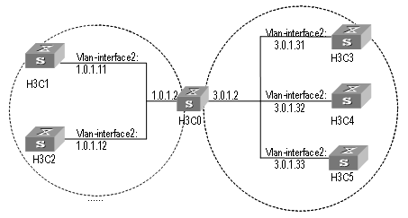
Figure 7-2 Typical NTP configuration network diagram
III. Configuration procedure
Configure Ethernet Switch H3C1:
# Enter system view.
<H3C1> system-view
# Set the local clock as the NTP master clock at stratum 2.
[H3C1] ntp-service refclock-master 2
Configure Ethernet Switch H3C2:
# Enter system view.
<H3C2> system-view
# Set H3C1 as the NTP server.
[H3C2] ntp-service unicast-server 1.0.1.11
The above examples synchronized H3C2 by H3C1. Before the synchronization, the H3C2 is shown in the following status:
[H3C2] display ntp-service status
clock status: unsynchronized
clock stratum: 16
reference clock ID: none
nominal frequency: 100.0000 Hz
actual frequency: 100.0000 Hz
clock precision: 2^17
clock offset: 0.0000 ms
root delay: 0.00 ms
root dispersion: 0.00 ms
peer dispersion: 0.00 ms
reference time: 00:00:00.000 UTC Jan 1 1900(00000000.00000000)
After the synchronization, H3C2 turns into the following status:
[H3C2] display ntp-service status
Clock status: synchronized
Clock stratum: 3
Reference clock ID: 1.0.1.11
Nominal frequency: 60.0002 Hz
Actual frequency: 60.0002 Hz
Clock precision: 2^17
Clock offset: -9.8258 ms
Root delay: 27.10 ms
Root dispersion: 49.29 ms
Peer dispersion: 10.94 ms
Reference time: 19:21:32.287 UTC Oct 24 2004(C5267F3C.49A61E0C)
By this time, H3C2 has been synchronized by H3C1 and is at stratum 3, higher than H3C1 by 1.
Display the sessions of H3C2 and you will see H3C2 has been connected with H3C1.
[H3C2] display ntp-service sessions
source reference stra reach poll now offset delay disper
********************************************************************
[12345]1.0.1.11 LOCAL(0) 3 377 64 16 -0.4 0.0 0.9
note: 1 source(master),2 source(peer),3 selected,4 candidate,5 configured
7.4.2 NTP Peer Configuration Example
I. Network requirements
On H3C3, set local clock as the NTP master clock at stratum 2. On H3C2, configure H3C1 as the time server in server mode and set the local equipment as in client mode. At the same time, H3C5 sets H3C4 as its peer. (Note: H3C3 supports to configure the local clock as the master clock)
II. Network diagram

Figure 7-3 Typical NTP configuration network diagram
III. Configuration procedure
Configure Ethernet Switch H3C3.
# Enter system view.
<H3C3> system-view
# Set the local clock as the NTP master clock at stratum 2.
[H3C3] ntp-service refclock-master 2
Configure Ethernet Switch H3C4.
# Enter system view.
<H3C4> system-view
# Set H3C1 as the NTP server at stratum 3 after synchronization.
[H3C4] ntp-service unicast-server 3.0.1.31
# Set H3C5 as peer
[H3C4] ntp-service unicast-peer 3.0.1.33
Configure Ethernet Switch H3C5.(H3C4 has been synchronized by H3C3)
# Enter system view.
<H3C5> system-view
# Set the local clock as the NTP master clock at stratum 1.
[H3C5] ntp-service refclock-master 1
# After performing local synchronization, set H3C4 as a peer.
[H3C5] ntp-service unicast-peer 3.0.1.32
The above examples configure H3C4 and H3C5 as peers and configure H3C5 as in active peer mode and H3C4 in passive peer mode. Since H3C5 is at stratum 1 and H3C4 is at stratum 3, synchronize H3C4 by H3C5.
After synchronization, H3C4 status is shown as follows:
[H3C4] display ntp-service status
Clock status: synchronized
Clock stratum: 2
Reference clock ID: 3.0.1.31
Nominal frequency: 60.0002 Hz
Actual frequency: 60.0002 Hz
Clock precision: 2^17
Clock offset: -9.8258 ms
Root delay: 27.10 ms
Root dispersion: 49.29 ms
Peer dispersion: 10.94 ms
Reference time: 19:21:32.287 UTC Oct 24 2004(C5267F3C.49A61E0C)
By this time, H3C4 has been synchronized by H3C5 and it is at stratum 2, or higher than H3C5 by 1.
Display the sessions of H3C4 and you will see H3C4 has been connected with H3C5.
[H3C4] display ntp-service sessions
source reference stra reach poll now offset delay disper
********************************************************************
[12345]3.0.1.33 LOCAL(0) 2 377 64 16 0.0 0.0 0.9
note: 1 source(master),2 source(peer),3 selected,4 candidate,5 configured
7.4.3 Configure NTP Broadcast Mode
I. Network requirements
On H3C3, set local clock as the NTP master clock at stratum 2 and configure to broadcast packets from Vlan-interface2. Configure H3C4 and H3C1 to listen to the broadcast from their Vlan-interface2 respectively. (Note: H3C3 supports to configure the local clock as the master clock)
II. Network diagram
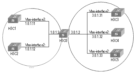
Figure 7-4 Typical NTP configuration network diagram
III. Configuration procedure
Configure Ethernet Switch H3C3:
# Enter system view.
<H3C3> system-view
# Set the local clock as the NTP master clock at stratum 2.
[H3C3] ntp-service refclock-master 2
# Enter Vlan-interface2 view.
[H3C3] interface vlan-interface 2
# Set it as broadcast server.
[H3C3-Vlan-Interface2] ntp-service broadcast-server
Configure Ethernet Switch H3C4:
# Enter system view.
<H3C4> system-view
# Enter Vlan-interface2 view.
[H3C4] interface vlan-interface 2
[H3C4-Vlan-Interface2] ntp-service broadcast-client
Configure Ethernet Switch H3C1:
# Enter system view.
<H3C1> system-view
# Enter Vlan-interface2 view.
[H3C1] interface vlan-interface 2
[H3C1-Vlan-Interface2] ntp-service broadcast-client
The above examples configured H3C4 and H3C1 to listen to the broadcast through Vlan-interface2, H3C3 to broadcast packets from Vlan-interface2. Since H3C1 and H3C3 are not located on the same segment, they cannot receive any broadcast packets from H3C3, while H3C4 is synchronized by H3C3 after receiving its broadcast packet.
After the synchronization, you can find the state of H3C4 as follows:
[H3C4] display ntp-service status
clock status: synchronized
clock stratum: 3
reference clock ID: LOCAL(0)
nominal frequency: 100.0000 Hz
actual frequency: 100.0000 Hz
clock precision: 2^17
clock offset: 0.0000 ms
root delay: 0.00 ms
root dispersion: 10.94 ms
peer dispersion: 10.00 ms
reference time: 20:54:25.156 UTC Mar 7 2002(C0325201.2811A112)
By this time, H3C4 has been synchronized by H3C3 and it is at stratum 3, higher than H3C3 by 1.
Display the status of H3C4 sessions and you will see H3C4 has been connected to H3C3.
[H3C2] display ntp-service sessions
source reference stra reach poll now offset delay disper
[12345]127.127.1.0 LOCAL(0) 7 377 64 57 0.0 0.0 1.0
[5]1.0.1.11 LOCAL(0) 3 0 64 - 0.0 0.0 0.0
[5]128.108.22.44 0.0.0.0 16 0 64 - 0.0 0.0 0.0
note: 1 source(master),2 source(peer),3 selected,4 candidate,5 configured
7.4.4 Configure NTP Multicast Mode
I. Network requirements
H3C3 sets the local clock as the master clock at stratum 2 and multicast packets from Vlan-interface2. Set H3C4 and H3C1 to receive multicast messages from their respective Vlan-interface2. (Note: H3C3 supports to configure the local clock as the master clock)
II. Network diagram
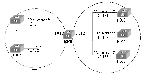
Figure 7-5 Typical NTP configuration network diagram
2) Configuration procedure
Configure Ethernet Switch H3C3:
# Enter system view.
<H3C3> system-view
# Set the local clock as a master NTP clock at stratum 2.
[H3C3] ntp-service refclock-master 2
# Enter Vlan-interface2 view.
[H3C3] interface vlan-interface 2
# Set it as a multicast server.
[H3C3-Vlan-Interface2] ntp-service multicast-server
Configure Ethernet Switch H3C4:
# Enter system view.
<H3C4> system-view
# Enter Vlan-interface2 view.
[H3C4] interface vlan-interface 2
# Enable multicast client mode.
[H3C4-Vlan-Interface2] ntp-service multicast-client
Configure Ethernet Switch H3C1:
# Enter system view.
<H3C1> system-view
# Enter Vlan-interface2 view.
[H3C1] interface vlan-interface 2
# Enable multicast client mode.
[H3C1-Vlan-Interface2] ntp-service multicast-client
The above examples configure H3C4 and H3C1 to receive multicast messages from Vlan-interface2, H3C3 multicast messages from Vlan-interface2. Since H3C1 and H3C3 are not located on the same segments, H3C1 cannot receive the multicast packets from H3C3, while H3C4 is synchronized by H3C3 after receiving the multicast packet.
7.4.5 Configure Authentication-Enabled NTP Server Mode
I. Network requirements
H3C1 sets the local clock as the NTP master clock at stratum 2. H3C2 sets H3C1 as its time server in Server mode and itself in Client mode and enables authentication. (Note: H3C1 supports to configure the local clock as the master clock)
II. Network diagram
Figure 7-6 Typical NTP configuration network diagram
III. Configuration procedure
Configure Ethernet Switch H3C1.
# Enter system view.
<H3C1> system-view
# Set the local clock as the master NTP clock at stratum 2.
[H3C1] ntp-service refclcok-master 2
Configure Ethernet Switch H3C2.
# Enter system view.
<H3C2> system-view
# Set H3C1 as time server.
[H3C2[ ntp-service unicast-server 1.0.1.11
# Enable authentication.
[H3C2] ntp-service authentication enable
# Set the key.
[H3C2] ntp-service authentication-keyid 42 authentication-mode md5 aNiceKey
# Set the key as reliable.
[H3C2] ntp-service reliable authentication-keyid 42
[H3C2] ntp-service unicast-server 1.0.1.11 authentication-keyid 42
The above examples synchronized H3C2 by H3C1. Since H3C1 has not been enabled authentication, it cannot synchronize H3C2. And now let us do the following additional configurations on H3C1.
# Enable authentication.
[H3C1] ntp-service authentication enable
# Set the key.
[H3C1] ntp-service authentication-keyid 42 authentication-mode md5 aNiceKey
# Configure the key as reliable.
[H3C1] ntp-service reliable authentication-keyid 42
Chapter 8 SSH Terminal Service
8.1 SSH Terminal Service
8.1.1 SSH Overview
This chapter introduces the secure shell (SSH) feature. When a user telnets to the switch from an insecure network, the SSH feature can provide secure information and powerful authentication functionality, thereby protecting the switch from attacks such as IP address spoofing and clear text password interception attacks.
The switch can act as either SSH server or SSH client. When used as an SSH server, the switch supports multiple connections with SSH clients; when used as an SSH client, the switch supports SSH connections with the SSH server-enabled switch, UNIX hosts, and so on.
Currently, the switch supports SSH 2.0.
Figure 8-1 and Figure 8-2 illustrate two methods for establishing an SSH channel between a client and the server:
l Connect through a LAN
l Connect through a WAN
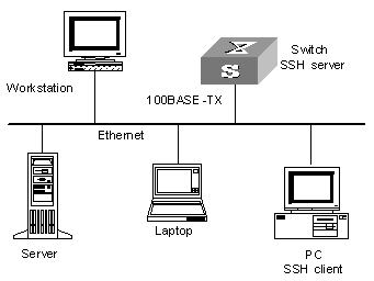
Figure 8-1 Establish an SSH channel through a LAN

Figure 8-2 Establish an SSH channel through a WAN
To establish an SSH authentication secure connection, the server and the client must go through the following five phases:
1) Version number negotiation:
l The client sends a TCP connection request.
l After the TCP connection is established, the server and the client negotiate the version number.
l If the negotiation succeeds, the key algorithm negotiation phase starts; otherwise, the server tears down the TCP connection.
2) Key algorithm negotiation:
l The server generates a RSA key pair randomly, and sends the public key in the key pair to the client.
l The client uses the public key from the server and a random number generated locally (in length of eight bytes) as parameters to calculate the session key.
l Using the public key from the server, the client encrypts the random number for calculating the session key and sends the result to the server.
l Using the local private key, the server decrypts the data sent by the client and obtains the random number used by the client.
l The server uses the public key and the random number from the client as parameters to calculate the session key with the same algorithm as on the client. The resulting key is 16 bytes long.
On completion of the above steps, the server and the client obtains the same session key. During the session, both ends use the same session key to perform encryption and decryption, thereby guaranteeing the security of data transfer.
3) Authentication mode negotiation:
l The client sends its username information to the server.
l The server initiates a procedure to authenticate the user. If the server is configured not to authenticate the user, the process proceeds to session request phase directly.
l The client employs an authentication mode to authenticate the server till the authentication succeeds or the server tears down the connection because of timeout.
& Note:
SSH provides two authentication modes: password authentication and RSA authentication.
1) Password authentication procedure:
l The client sends the username and password to the server;
l The server compares the username and password sent from the client with the local configuration. If it finds an exact match, the authentication succeeds.
2) RSA authentication procedure:
l The server configures an RSA public key for the client;
l The client sends its RSA public key member module to the server;
l The server performs validity authentication on the member module. If the authentication succeeds, the server generates a random number, encrypts it using the RSA public key from the client, and sends the encrypted information back to the client;
l Both the server and the client uses the random number and the session ID with the length of 16 characters as parameters to calculate the authentication data;
l The client sends the authentication data it generates to the server;
l The server compares the authentication data from the client with that locally calculated. If they match, the authentication succeeds.
4) Session request: If the authentication succeeds, the client sends a session request to the server. When the server has successfully processed the request, SSH enters the interactive session phase.
5) Interactive session: The client and the server exchange data till the session is over.
8.1.2 SSH Server Configuration
The following table describes the SSH server configuration tasks.
Table 8-1 SSH2.0 Configuration tasks
|
Num |
Item |
Command |
Description |
|
1 |
Entering system view |
<H3C> system-view |
- |
|
2 |
Entering VTY type of user interface view |
[H3C] user-interface vty X X |
- |
|
3 |
Configure the protocol supported by current user interface |
[H3C-ui-vtyX-X] protocol inbound { all | ssh | telnet } |
Optional |
|
4 |
Returning to system view |
[H3C-ui-vtyX-X] quit |
- |
|
5 |
Generating a local RSA key pair |
[H3C] rsa local-key-pair create |
Required |
|
Destroying a local RSA key pair |
[H3C] rsa local-key-pair destroy |
||
|
6 |
Configure the SSH user authentication mode |
[H3C] ssh user username [ authentication-type { password | rsa | password-publickey | all } ] |
Required By default, users are unable to log in. |
|
7 |
Configure default authentication type for SSH users |
[H3C]ssh authentication-type default [ password | rsa | all | password-publickey ] |
Required; By default, an users are unable to log in to the system. |
|
8 |
Configure the updating cycle of the server key |
[H3C] ssh server rekey-interval hours |
Optional By default, the system does not update the server key. |
|
9 |
Configure the SSH authentication timeout |
[H3C] ssh server timeout seconds |
Optional By default, it is 60 seconds. |
|
10 |
Configure the number of SSH authentication retries |
[H3C] ssh server authentication-retries times |
Optional By default, it is three times. |
|
11 |
Enter public key view |
[H3C] rsa peer-public-key key-name |
Required |
|
12 |
Entering public key edit view to edit the key |
[H3C-rsa-public-key] public-key-code begin |
Required |
|
13 |
Exiting public key edit view |
[H3C-rsa-public-key] public-key-code end |
Required |
|
14 |
Specifying the public key for an SSH user |
[H3C] ssh user username assign rsa-key keyname |
Required |
|
15 |
Configure first-authentication SSH server |
[H3C] ssh client first-time enable |
Optional By default, the system does not perform the first authentication. |
|
16 |
Configure the SSH compatibility mode |
[H3C] ssh server compatible_ssh1x enable |
Optional By default, the server is compatible with the SSH1.x client. |
I. Configuring the protocol the current user interface supports
Use this configuration task to specify the protocol the current user interface supports.
Perform the following configuration in VTY user interface view.
Table 8-2 Configure the protocol the current user interface supports
|
Operation |
Command |
|
Configure the protocol the current user interface supports |
protocol inbound { all | pad | ssh | telnet } |
By default, the system supports all protocols.
![]() Caution:
Caution:
l If the supported protocol configured in the user interface is SSH, make sure to configure the authentication mode for logging into the user interface to authentication-mode scheme (using AAA authentication mode).
l If the authentication mode is configured as authentication-mode password or authentication-mode none, the configuration of protocol inbound ssh will fail, and vice versa.
II. Generating or destroying an RSA key pair
Use this configuration task to generate or destroy an RSA key pair (including the host key and server key) of the server. The naming conventions for the keys are switchname + host and switchname + server respectively.
After this command is entered, the system prompts you to input the number of the key pair bits. Pay attention to the following:
l The host key and the server key must have a difference of at least 128 bits in length.
l The minimum and maximum lengths for the host key and the server key are 512 bits and 2048 bits respectively.
Perform the following configuration in system view.
Table 8-3 Generate an RSA key pair
|
Operation |
Command |
|
Generate an RSA key pair |
rsa local-key-pair create |
|
Destroy an RSA key pair |
rsa local-key-pair destroy |
![]() Caution:
Caution:
l Generating the RSA key pair of the server is the first step to perform after SSH login.
l This command needs to be performed only once; you need not re-perform it after rebooting the switch.
l If a key pair exists before the configuration, a prompt will appear asking if you want to replace it.
l When an SSH user logs in, the key generated by the server must longer than or equal to 768 bits. By default, the key generated by the server is 512 bits.
III. Configuring the user authentication mode
Use this configuration task to specify the authentication mode for an SSH user. You must specify an authentication mode for a new user; otherwise, the new user will not be able to log in.
Perform the following configuration in system view.
Table 8-4 Configure the authentication mode for an SSH user
|
Operation |
Command |
|
Configure the authentication mode for an SSH user |
ssh user username [ authentication-type { password | rsa | password-publickey | all } ] |
|
Restore the default unable-to-login mode |
undo ssh user username authentication-type |
By default, no login authentication mode is specified, that is, SSH users are unable to log in.
IV. Configuring the updating cycle of the server key
Use this configuration task to set the updating cycle of the server key to secure the SSH connection in best effort.
Perform the following configuration in system view
Table 8-5 Configure the updating cycle of the server key
|
Operation |
Command |
|
Configure the updating cycle of the server key |
ssh server rekey-interval hours |
|
Cancel the updating cycle configuration |
undo ssh server rekey-interval |
By default, the system does not update the server key.
V. Configuring the authentication timeout
Use this configuration task to set the authentication timeout of SSH connections.
Perform the following configuration in system view.
Table 8-6 Set the SSH authentication timeout
|
Operation |
Command |
|
Set the SSH authentication timeout |
ssh server timeout seconds |
|
Restore the default SSH authentication timeout |
undo ssh server timeout |
By default, the authentication timeout is 60 seconds.
VI. Configuring the number of authentication retries
Use this configuration task to set the number of authentication retries an SSH user can request for a connection, thereby preventing illegal behaviors such as malicious guessing.
Perform the following configuration in system view.
Table 8-7 Configure the number of SSH authentication retries
|
Operation |
Command |
|
Configure the number of SSH authentication retries |
ssh server authentication-retries times |
|
Restore the default number of SSH authentication retries |
undo ssh server authentication-retries |
By default, the number of authentication retries is 3.
VII. Entering the public key view
Use this configuration command to enter the public key view and specify the name of the public key of the client.
Perform the first configuration in the following table in system view.
Table 8-8 Public key configuration
|
Operation |
Command |
|
Enter the public key view |
rsa peer-public-key key-name |
|
Exit the public view and return to the system view |
peer-public-key end |
& Note:
The configuration commands are applicable to the environments where the server employs RSA authentication on SSH users. If the server adopts password authentication on SSH users, these configurations are not necessary.
VIII. Entering the public key edit view
After entering the public key view by the rsa peer-public-key command, you can use the public-key-code begin command to enter the public key edit view and input the public key of the client.
When inputting the public key, you may type spaces between the characters (the system will delete the spaces automatically), or press <Enter> and then continue to input the key. Note that the public key must be a hexadecimal string coded in the public key format.
Perform the following configuration in public key view.
Table 8-9 Enter the public key edit view
|
Operation |
Command |
|
Enter the public key edit view |
public-key-code begin |
IX. Exiting the public key edit view
Use this configuration task to return from the public key edit view to the public key view and save the input public key. Before saving the input public key, the system will check the validity of the key:
l If the public key string contains any illegal character, the configured key is invalid;
l If the configured key is valid, it will be saved to the public key list.
Perform the following configuration in public key edit view.
Table 8-10 Exit the public key edit view
|
Operation |
Command |
|
Exit the public key edit view |
public-key-code end |
X. Specifying the public key for an SSH user
Use this configuration task to specify an existing public key for an SSH user.
Perform the following configuration in system view.
Table 8-11 Specify the public key for an SSH user
|
Operation |
Command |
|
Specify the public key for an SSH user |
ssh user username assign rsa-key keyname |
|
Cancel the corresponding relationship between the user and the public key |
undo ssh user username assign rsa-key |
XI. Configuring the server compatibility mode
Use this configuration task to set whether the server should be compatible with the SSH 1.x client.
Perform the following configuration in system view.
Table 8-12 Configure the compatibility mode
|
Operation |
Command |
|
Set the server to be compatible with the SSH 1.x client |
ssh server compatible_ssh1x enable |
|
Set the server to be incompatible with the SSH 1.x client |
undo ssh server compatible_ssh1x |
By default, the server is compatible with the SSH 1.x client.
8.1.3 SSH Client Configuration
The following sections describe the SSH client configuration tasks.
l Set to perform the first-time authentication on the SSH server to be accessed
l Specifying the public key of the server
l Configuring the first-time authentication of the server
I. Starting the SSH client
Use this configuration task to enable the SSH client, establish the connection with the server, and carry out interactive session.
Perform the following configuration in system view.
Table 8-13 Start the SSH client
|
Operation |
Command |
|
Start the SSH client |
ssh2 { host-ip | host-name } [ port-num ] [ prefer_kex { dh_group1 | dh_exchange_group } ] [ prefer_ctos_cipher { des | 3des | aes128 } ] [ prefer_stoc_cipher { des | 3des | aes128 } ] [ prefer_ctos_hmac { sha1 | sha1_96 | md5 | md5_96 } ] [ prefer_stoc_hmac { sha1 | sha1_96 | md5 | md5_96 } ] |
II. Specifying the public key of the server
Use this configuration task to allocate a existent public key to the client.
Perform the following configuration in system view.
Table 8-14 Specify the public key of the server
|
Operation |
Command |
|
Specify the public key of the server |
ssh client server-ip assign rsa-key keyname |
|
Cancel the corresponding relationship between the server and the public key |
undo ssh client server-ip assign rsa-key |
III. Configuring the first-time authentication of the server
Use this configuration task to configure or cancel the first-time authentication of the server performed by the SSH client.
The first-time authentication means that when the SSH client accesses the server for the first time in the case that there is no local copy of the server’s public key, the user can choose to proceed to access the server and save a local copy of the server’s public key; when the client accesses the server next time, it uses the saved public key to authenticate the server.
Perform the following configuration in system view.
Table 8-15 Configure the first-time authentication of the server
|
Operation |
Command |
|
Configure the first-time authentication of the server |
ssh client first-time enable |
|
Cancel the first-time authentication of the server |
undo ssh client first-time |
By default, the client does not perform the first-time authentication.
8.1.4 Displaying and Debugging SSH
On completion of the above configurations, you can use the display command in any view to view the operation of the configured SSH and further verify the result of the configurations. You can also debug SSH by performing the debugging command in user view.
Table 8-16 Display information relevant to SSH
|
Operation |
Command |
|
Display the public key of the host key pair and the server key pair of the server |
display rsa local-key-pair public |
|
Display the public key of the specified RSA key pair of the client |
display rsa peer-public-key [ brief | name keyname ] |
|
Display the SSH status information and session information |
display ssh server { status | session } |
|
Display information about the SSH user |
display ssh user-information [ username ] |
|
Enable SSH debugging |
debugging ssh server { vty index | all } |
|
Disable SSH debugging |
undo debugging ssh server { vty index | all } |
8.1.5 SSH Server Configuration Example
I. Network requirements
As shown in Figure 8-3, a PC (SSH client) running SSH 2.0-enabled client software establishes a local connection with the switch (SSH server) to better guarantee the security of exchanged information.
II. Network diagram
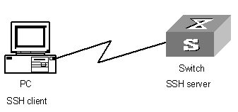
Figure 8-3 Network diagram for SSH server
III. Configuration procedure
1) Generate the RSA key.
[H3C] rsa local-key-pair create
& Note:
If the configuration for generating the local key has already been completed, skip this step.
2) Set the user login authentication mode.
The following shows the configuration methods for both password authentication and RSA public key authentication.
l Password authentication.
# Create the local user client001, and set the authentication mode of the user interface to AAA.
[H3C] user-interface vty 0 4
[H3C-ui-vty0-4] authentication-mode scheme
# Specify the login protocol for user client001 as SSH.
[H3C-ui-vty0-4] protocol inbound ssh
[H3C] local-user client001
[H3C-luser-client001] password simple H3C
[H3C] ssh user client001 authentication-type password
& Note:
You can use the default values for SSH authentication timeout and retries. After completing the above configurations, you can run the SSH 2.0-enabled client software on any other terminal connected with the switch and access the switch with the username client001 and password H3C.
l RSA public key authentication.
# Create the local user client001, and set the authentication mode of the user interface to AAA.
[H3C] user-interface vty 0 4
[H3C-ui-vty0-4] authentication-mode scheme
# Specify the login protocol for user client002 as SSH.
[H3C-ui-vty0-4] protocol inbound ssh
# Set the authentication mode for the remote user on the switch to publickey.
[H3C] ssh user client002 authentication-type publickey
# Using the SSH 2.0-enabled client software, randomly generate an RSA key pair and send the public key to the server.
Configure the public key of the client.
[H3C] rsa peer-public-key H3C002
[H3C-rsa-public-key] public-key-code begin
[H3C-rsa-key-code] 308186028180739A291ABDA704F5D93DC8FDF84C427463
[H3C-rsa-key-code] 1991C164B0DF178C55FA833591C7D47D5381D09CE82913
[H3C-rsa-key-code] D7EDF9C08511D83CA4ED2B30B809808EB0D1F52D045DE4
[H3C-rsa-key-code] 0861B74A0E135523CCD74CAC61F8E58C452B2F3F2DA0DC
[H3C-rsa-key-code] C48E3306367FE187BDD944018B3B69F3CBB0A573202C16
[H3C-rsa-key-code] BB2FC1ACF3EC8F828D55A36F1CDDC4BB45504F020125
[H3C-rsa-key-code] public-key-code end
[H3C-rsa-public-key] peer-public-key end
[H3C]
#Allocate an existent public key H3C002 to user client002.
[H3C] ssh user client002 assign rsa-key H3C002
Start the SSH client software on the terminal preserving the RSA private key, and perform the corresponding configurations to establish the SSH connection.
8.1.6 SSH Client Configuration Example
I. Network requirements
As shown in Figure 8-4:
l Switch A is used as an SSH client.
l Switch B is used as the SSH server, and the IP address is 10.165.87.136.
II. Network diagram
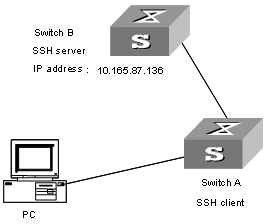
Figure 8-4 Network diagram for SSH client
III. Configuration procedure
Configure the client to perform the first-time authentication of the server.
l Employ password authentication mode, and start using the default encryption algorithm.
# Log onto the SSH2 server with IP address 10.165.87.136.
[H3C] ssh2 10.165.87.136
Please input the username:sshuser1
Trying 10.165.87.136
Press CTRL+K to abort
Connected to 10.165.87.136 ...
Enter password:
*********************************************************
* All rights reserved (1997-2004) *
* Without the owner's prior written consent, *
*no decompiling or reverse-engineering shall be allowed.*
*********************************************************
<H3C>
# Configure the client to authenticate the server for the first time.
<H3C> system-view
[H3C] ssh client first-time enable
Access the remote server and perform operations.
l Employ RSA public key authentication mode, and start using the corresponding encryption algorithm configured.
[H3C] ssh2 10.165.87.136 22 perfer_kex dh_group1 perfer_ctos_cipher des perfer_stoc_cipher 3des perfer_ctos_hmac md5 perfer_stoc_hmac md5
Please input the username: client003
Trying 10.165.87.136...
Press CTRL+K to abort
Connected to 10.165.87.136...
The Server is not autherncated. Do you continue access it?(Y/N):y
Do you want to save the server's public key?(Y/N):y
*********************************************************
* All rights reserved (1997-2004) *
* Without the owner's prior written consent, *
*no decompiling or reverse-engineering shall be allowed.*
*********************************************************
<H3C>
# Configure the client to authenticate the server for the first time.
<H3C> system-view
System View: return to User View with Ctrl+Z.
[H3C] ssh client first-time enable
Access the remote server and perform operations.
8.2 SFTP Service
8.2.1 SFTP Overview
Secure FTP is established on SSH connections, which makes remote users able to securely log in to the switch and perform file management and transfer operations such as system upgrade, and thereby providing higher security for data transfer. At the same time, since the switch can be used as a client, users can log in to remote devices to transfer files securely.
8.2.2 SFTP Server Configuration
SFTP server configuration tasks are described in this section:
l Configuring the service type to be used
l Starting the SFTP server
I. Configuring the service type to be used
Use this configuration task to set the SSH service type to be used.
Perform the following configuration in system view.
Table 8-17 Configure the service type to be used
|
Operation |
Command |
|
Configure the service type to be used |
ssh user username service-type { stelnet | sftp | all } |
|
Restore the default service type |
undo ssh user username service-type |
By default, the service type is stelnet.
II. Starting the SFTP server
Perform the following configuration in system view.
Table 8-18 Start the SFTP server
|
Operation |
Command |
|
Start the SFTP server |
sftp server enable |
|
Shut down the SFTP server |
undo sftp server enable |
By default, the SFTP server is shut down.
8.2.3 SFTP Client Configuration
The following table describes the SFTP client configuration tasks.
Table 8-19 SFTP client configuration tasks
|
Num |
Item |
Command |
Description |
|
|
1 |
Enter system view |
<H3C> system-view |
- |
|
|
2 |
Starting the SFTP client |
[H3C] sftp ipaddr [ prefer_kex { dh_group1 | dh_exchange_group } ] [ prefer_ctos_cipher { des | 3des | aes128 } ] [ prefer_stoc_cipher { des | 3des | aes128 } ] [ prefer_ctos_hmac { sha1 | sha1_96 | md5 | md5_96 } ] [ prefer_stoc_hmac { sha1 | sha1_96 | md5 | md5_96 } ] |
Required |
|
|
3 |
Shut down the SFTP client |
sftp-client> bye |
Optional |
|
|
sftp-client> exit |
||||
|
sftp-client> quit |
||||
|
4 |
SFTP directory operation |
Chang the current directory |
sftp-client> cd [remote-path ] |
- |
|
Return to the upper directory |
sftp-client> cdup |
|||
|
Display the current directory |
sftp-client> pwd |
|||
|
Display the file list in the specified directory |
sftp-client> dir [remote-path ] |
|||
|
sftp-client> ls [remote-path ] |
||||
|
Delete a directory on the server |
sftp-client> rmdir remote-path |
|||
|
5 |
SFTP file operation |
Change the name of the specified file on the server |
sftp-client> rename oldname newname |
Optional |
|
Download a file from the remote server |
sftp-client> get remote-file [ local-file ] |
|||
|
Upload a local file to the remote server |
sftp-client> put local-file [ remote-file ] |
|||
|
Display the file list in the specified directory |
sftp-client> dir [remote-path ] |
|||
|
sftp-client> ls [remote-path ] |
||||
|
Delete a file from the server |
sftp-client> remove remote-file |
|||
|
sftp-client> delete remote-file |
||||
|
6 |
Command help on the client |
sftp-client> help [ command ] |
Optional |
|
I. Starting the SFTP client
Use this configuration task to start the SFTP client program, establish a connection with the remote SFTP server, and enter the SFTP client view.
Perform the following configuration in system view.
Table 8-20 Start the SFTP client
|
Operation |
Command |
|
Start the SFTP client |
sftp ipaddr [ prefer_kex { dh_group1 | dh_exchange_group } ] [ prefer_ctos_cipher { des | 3des | aes128 } ] [ prefer_stoc_cipher { des | 3des | aes128 } ] [ prefer_ctos_hmac { sha1 | sha1_96 | md5 | md5_96 } ] [ prefer_stoc_hmac { sha1 | sha1_96 | md5 | md5_96 } ] |
II. Shutting down the SFTP client
Use this configuration task to shut down the SFTP client program.
Perform the following configuration in SFTP client view.
Table 8-21 Shut down the SFTP client
|
Operation |
Command |
|
Shut down the SFTP client |
bye |
|
exit |
|
|
quit |
& Note:
The three commands, bye, exit, and quit, have the same functionality. You can also use the quit command in port group view.
III. SFTP directory operations
As shown in Table 8-22, available SFTP directory operations include: change or display the current directory, create or delete a directory, display the specified file or directory.
Perform the following configuration in SFTP client view.
Table 8-22 SFTP directory operations
|
Operation |
Command |
|
Change the current directory |
cd remote-path |
|
Return to the upper directory |
cdup |
|
Display the current directory |
pwd |
|
Display the list of files in the specified directory |
dir [ remote-path ] |
|
ls [ remote-path ] |
|
|
Create a new directory on the server |
mkdir remote-path |
|
Delete a directory from the server |
rmdir remote-path |
& Note:
The dir command and the ls command have the same functionality.
IV. SFTP file operations
As shown in Table 8-23, available SFTP file operations include: change the name of a file, download a file, upload a file, display the list of files, and delete a file.
Perform the following configuration in SFTP user view.
Table 8-23 SFTP file operations
|
Operation |
Command |
|
Change the name of the specified file on the server |
rename old-name new-name |
|
Download a file from the remote server |
get remote-file [ local-file ] |
|
Upload a local file to the remote server |
put local-file [ remote-file ] |
|
Display the list of files in the specified directory |
dir [ remote-path ] |
|
ls [ remote-path ] |
|
|
Delete a file from the server |
delete remote-file |
|
remove remote-file |
& Note:
l The dir command and the ls command have the same functionality.
l The delete command and the remove command have the same functionality.
V. Displaying help information
Use this command to display command-relevant help information such as the format of the command, parameter configurations, and so on.
Perform the following configuration in SFTP client view.
Table 8-24 Display help information for client commands
|
Operation |
Command |
|
Display help information for client commands |
help [ command-name ] |
8.2.4 SFTP Configuration Example
I. Network requirements
As shown in Figure 8-5:
l Switch A is used as the SFTP server, and its IP address is 10.111.27.91;
l Switch B is used as the SFTP client;
l An SFTP user is configured with the username “8040” and password “H3C".
II. Network diagram
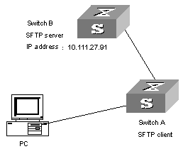
Figure 8-5 Network diagram for SFTP
III. Configuration procedure
1) Configure Switch B.
# Start the SFTP server.
[H3C] sftp-server enable
# Specify the service type as SFTP.
[H3C] ssh user 8040 service-type sftp
# Set the authentication mode to password.
[H3C] ssh user 8040 authentication-type password
2) Configure Switch A
# Configure the server with a public key whose name is the IP address of the server.
[H3C] rsa peer-public-key 10.111.27.91
[H3C-rsa-public-key] public-key-code begin
[H3C-rsa-key-code] 308186028180739A291ABDA704F5D93DC8FDF84C427463
[H3C-rsa-key-code] 1991C164B0DF178C55FA833591C7D47D5381D09CE82913
[H3C-rsa-key-code] D7EDF9C08511D83CA4ED2B30B809808EB0D1F52D045DE4
[H3C-rsa-key-code] 0861B74A0E135523CCD74CAC61F8E58C452B2F3F2DA0DC
[H3C-rsa-key-code] C48E3306367FE187BDD944018B3B69F3CBB0A573202C16
[H3C-rsa-key-code] BB2FC1ACF3EC8F828D55A36F1CDDC4BB45504F020125
[H3C-rsa-key-code] public-key-code end
[H3C-rsa-public-key] peer-public-key end
[H3C] ssh client 10.111.27.91 assign rsa-key 10.111.27.91
# Establish the SSH connection between the client and the server.
[H3C] ssh2
Please input the username:8040
Trying
Press CTRL+K to abort
Connected to 10.111.27.91 ...
Enter password:H3C
*********************************************************
* All rights reserved (1997-2004) *
* Without the owner's prior written consent, *
*no decompiling or reverse-engineering shall be allowed.*
*********************************************************
<H3C>
# Establish a connection with the remote SFTP server and enter the SFTP client view.
<H3C> system-view
[H3C] sftp 10.111.27.91
# Display the current directory of the server, delete file z, and check if the directory has been deleted successfully.
sftp-client> dir
-rwxrwxrwx 1 noone nogroup 1759 Aug 23 06:52 config.cfg
-rwxrwxrwx 1 noone nogroup 225 Aug 24 08:01 pubkey2
-rwxrwxrwx 1 noone nogroup 283 Aug 24 07:39 pubkey1
drwxrwxrwx 1 noone nogroup 0 Sep 01 06:22 new
-rwxrwxrwx 1 noone nogroup 225 Sep 01 06:55 pub
-rwxrwxrwx 1 noone nogroup 0 Sep 01 08:00 z
sftp-client> delete z
Remove this File?(Y/N)
flash:/zy
File successfully Removed
sftp-client> dir
-rwxrwxrwx 1 noone nogroup 1759 Aug 23 06:52 config.cfg
-rwxrwxrwx 1 noone nogroup 225 Aug 24 08:01 pubkey2
-rwxrwxrwx 1 noone nogroup 283 Aug 24 07:39 pubkey1
drwxrwxrwx 1 noone nogroup 0 Sep 01 06:22 new
-rwxrwxrwx 1 noone nogroup 225 Sep 01 06:55 pub
# Create a new directory new1, and check if the new directory has been created successfully.
sftp-client> mkdir new1
New path created
sftp-client> dir
-rwxrwxrwx 1 noone nogroup 1759 Aug 23 06:52 config.cfg
-rwxrwxrwx 1 noone nogroup 225 Aug 24 08:01 pubkey2
-rwxrwxrwx 1 noone nogroup 283 Aug 24 07:39 pubkey1
drwxrwxrwx 1 noone nogroup 0 Sep 01 06:22 new
-rwxrwxrwx 1 noone nogroup 225 Sep 01 06:55 pub
drwxrwxrwx 1 noone nogroup 0 Sep 02 06:30 new1
# Change the directory name new1 to new2, and check if the directory name has been changed successfully.
sftp-client> rename new1 new2
sftp-client> dir
-rwxrwxrwx 1 noone nogroup 1759 Aug 23 06:52 config.cfg
-rwxrwxrwx 1 noone nogroup 225 Aug 24 08:01 pubkey2
-rwxrwxrwx 1 noone nogroup 283 Aug 24 07:39 pubkey1
drwxrwxrwx 1 noone nogroup 0 Sep 01 06:22 new
-rwxrwxrwx 1 noone nogroup 225 Sep 01 06:55 pub
drwxrwxrwx 1 noone nogroup 0 Sep 02 06:33 new2
# Download file pubkey2 from the server to a local device, and change the file name to pu.
sftp-client> get pubkey2 pu
Downloading file successfully ended
# Upload local file pu to the server, change the file name to puk, and check if the operations are successful.
sftp-client> put pu puk
Uploading file successfully ended
sftp-client> dir
-rwxrwxrwx 1 noone nogroup 1759 Aug 23 06:52 config.cfg
-rwxrwxrwx 1 noone nogroup 225 Aug 24 08:01 pubkey2
-rwxrwxrwx 1 noone nogroup 283 Aug 24 07:39 pubkey1
drwxrwxrwx 1 noone nogroup 0 Sep 01 06:22 new
drwxrwxrwx 1 noone nogroup 0 Sep 02 06:33 new2
-rwxrwxrwx 1 noone nogroup 283 Sep 02 06:35 pu
-rwxrwxrwx 1 noone nogroup 283 Sep 02 06:36 puk
sftp-client>
# Exit SFTP.
sftp-client> quit
Bye
<H3C>
