- Table of Contents
-
- 17-High Availability Configuration Guide
- 00-Preface
- 01-Ethernet OAM configuration
- 02-CFD configuration
- 03-DLDP configuration
- 04-ERPS configuration
- 05-Smart Link configuration
- 06-Monitor Link configuration
- 07-S-Trunk configuration
- 08-Error code detection configuration
- 09-VRRP configuration
- 10-BFD configuration
- 11-Track configuration
- 12-Process placement configuration
- 13-Interface collaboration configuration
- Related Documents
-
| Title | Size | Download |
|---|---|---|
| 10-BFD configuration | 487.73 KB |
Contents
Single-hop detection and multihop detection
Restrictions and guidelines: BFD configuration
Configuring BFD sessions in echo packet mode
About BFD session creation methods
Configuring detection time settings
Configuring BFD sessions in control packet mode
About BFD session creation methods
Configuring the session establishment mode
Configuring the detection mode
Configuring a static BFD session
Configuring detection time settings
Configuring the authentication mode
Configuring the destination port number for multihop BFD control packets
Configuring the notification delay timer for session establishment failures
Associating the interface state with BFD
Configuring BFD session flapping suppression
Configuring BFD session local discriminators reserved for third-party containers
Enabling SNMP notifications for BFD
Delaying session negotiation for down BFD and SBFD sessions
Restrictions and guidelines: SBFD configuration
Configuring the initiator for LDP LSP detection
Configuring the initiator for MPLS TE tunnel detection
Configuring the initiator for SR-MPLS TE policy detection
Configuring the initiator for SRv6 locator detection
Configuring the initiator for SRv6 TE policy detection
Delaying session negotiation for down SBFD sessions
Configuring BFD
About BFD
Bidirectional forwarding detection (BFD) provides a general-purpose, standard, medium- and protocol-independent fast failure detection mechanism. It can detect and monitor the connectivity of forwarding paths to detect communication failures quickly so that measures can be taken to ensure service continuity and enhance network availability.
BFD can uniformly and quickly detect the failures of the bidirectional forwarding paths between two devices for upper-layer protocols such as routing protocols. The hello mechanism used by upper-layer protocols needs seconds to detect a link failure, while BFD can provide detection measured in milliseconds.
Mechanism
BFD establishes a session between two network devices to detect failures on the bidirectional forwarding paths between the devices and provide services for upper-layer protocols. BFD provides no neighbor discovery mechanism. Protocols that BFD services notify BFD of devices to which it needs to establish sessions. After a session is established, if no BFD control packet is received from the peer within the negotiated BFD interval, BFD notifies a failure to the protocol, which then takes appropriate measures.
Figure 1 describes the operation of BFD for OSPF.
1. OSPF discovers neighbors by sending Hello packets and establishes neighbor relationships.
2. After establishing neighbor relationships, OSPF notifies BFD of the neighbor information, including destination and source addresses.
3. BFD uses the information to establish BFD sessions.
Figure 1 BFD session establishment
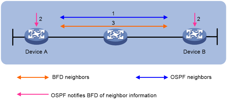
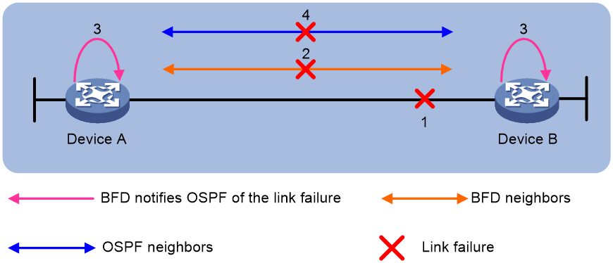
Figure 2 describes the BFD fault detection process.
1. BFD detects a link failure and tears down the session.
2. BFD notifies the neighbor unreachability to OSPF.
3. OSPF terminates the neighbor relationship on the link.
Single-hop detection and multihop detection
BFD can be used for single-hop and multihop detections.
· Single-hop detection—Detects the IP connectivity between two directly connected systems, for example, Device A and Device B as shown in Figure 3.

· Multihop detection—Detects any of the paths between two systems, for example, Device A and Device B as shown in Figure 4. These paths have multiple hops, and might overlap.

BFD session modes
BFD session modes include echo mode (using echo packets) and control mode (using control packets).
Echo mode
Echo packets are encapsulated into UDP packets. The packet contains destination port 3785, a destination IP address (transmitting interface's IP address), and a source IP address (transmitting interface's IP address).
The local end of the link sends echo packets to establish BFD sessions and monitor link status. The peer end does not establish BFD sessions and only forwards the packets back to the originating end. If the local end does not receive echo packets from the peer end within the detection time, it considers the session to be down.
BFD sessions in echo packet mode do not require both ends to support BFD. Upon receiving BFD echo packets, the peer end loops back the packets for detection purposes.
An echo-mode BFD session supports only single-hop detection and is independent of the operating mode.
Control mode
Control packets are encapsulated into UDP packets with port number 3784 for single-hop detection or port number 4784 for multihop detection.
The two ends of the link negotiate the establishment of BFD sessions by using the session parameters carried in control packets. Session parameters include session discriminators, desired minimum packet sending and receiving intervals, and local BFD session state.
Supported features
Table 1 shows the features supported by BFD.
Table 1 Features supported by BFD
|
Feature |
Reference |
|
Link aggregation |
Ethernet link aggregation in Layer 2—LAN Switching Configuration Guide |
|
IPv4 static routing |
Static routing in Layer 3—IP Routing Configuration Guide |
|
IPv6 static routing |
IPv6 static routing in Layer 3—IP Routing Configuration Guide |
|
RIP |
RIP in Layer 3—IP Routing Configuration Guide |
|
OSPF |
OSPF in Layer 3—IP Routing Configuration Guide |
|
OSPFv3 |
OSPFv3 in Layer 3—IP Routing Configuration Guide |
|
IS-IS |
IS-IS in Layer 3—IP Routing Configuration Guide |
|
BGP |
BGP in Layer 3—IP Routing Configuration Guide |
|
MPLS |
MPLS OAM in IP Multicast Configuration Guide |
|
RSVP |
RSVP in MPLS Configuration Guide |
|
SR-MPLS TE policy |
SR-MPLS TE policy in Segment Routing Configuration Guide |
|
Track |
"Configuring Track" |
|
S-Trunk |
"Configuring S-Trunk" |
|
SDWAN |
SDWAN in SDWAN Configuration Guide |
Protocols and standards
· RFC 5880, Bidirectional Forwarding Detection (BFD)
· RFC 5881, Bidirectional Forwarding Detection (BFD) for IPv4 and IPv6 (Single Hop)
· RFC 5882, Generic Application of Bidirectional Forwarding Detection (BFD)
· RFC 5883, Bidirectional Forwarding Detection (BFD) for Multihop Paths
· RFC 5884, Bidirectional Forwarding Detection (BFD) for MPLS Label Switched Paths (LSPs)
· RFC 5885, Bidirectional Forwarding Detection (BFD) for the Pseudowire Virtual Circuit Connectivity Verification (VCCV)
· RFC 7130, Bidirectional Forwarding Detection (BFD) on Link Aggregation Group (LAG) Interfaces
BFD tasks at a glance
1. Configuring BFD sessions in echo packet mode
¡ Creating a static BFD session
¡ Configuring detection time settings
2. Configuring BFD sessions in control packet mode
¡ Configuring a static BFD session
¡ Configuring detection time settings
¡ Configuring the authentication mode
¡ Configuring the destination port number for multihop BFD control packets
¡ Configuring the notification delay timer for session establishment failures
¡ Associating the interface state with BFD
3. Configuring BFD session flapping suppression
5. Configuring BFD session local discriminators reserved for third-party containers
6. Enabling SNMP notifications for BFD
7. Configuring BFD optimization
8. Delaying session negotiation for down BFD and SBFD sessions
Restrictions and guidelines: BFD configuration
· BFD session flapping might occur on an aggregate interface with member ports on different cards. When the card that receives and sends BFD packets is removed or restarted, the backup card might not immediately take over. For example, the backup card will not take over when the card has a short detection time or a large number of BFD sessions.
· By default, the device runs BFD version 1 and is compatible with BFD version 0. You cannot change the BFD version to 0 through commands. When the peer device runs BFD version 0, the local device automatically switches to BFD version 0.
· After a BFD session is established, the two ends negotiate BFD parameters, including minimum sending interval, minimum receiving interval, initialization mode, and packet authentication, by exchanging negotiation packets. They use the negotiated parameters without affecting the session status.
Configuring BFD sessions in echo packet mode
About BFD session creation methods
A BFD session can be created manually by using the bfd static command or created dynamically when an application module collaborates with BFD.
Restrictions and guidelines
As a best practice, execute the bfd echo-source-ip or bfd echo-source-ipv6 command only one end, and do not configure the source IPv4 or IPv6 address to be on the same network segment as any local interface's IPv4 or IPv6 address. If you configure such a source IPv4 or IPv6 address, a large number of ICMP redirect packets might be sent from the peer, resulting in link congestion.
Creating a static BFD session
About this task
A static BFD session in echo packet mode can be used to perform single-hop detection or multihop detection.
Restrictions and guidelines
You need to create a static BFD session in echo packet mode on only the local device to perform detection.
When creating a static BFD session, you must specify a peer IPv4 or IPv6 address. The system checks only the format of the IP address but not its correctness. If the peer IPv4 or IPv6 address is incorrect, the static BFD session cannot be established.
Different static BFD sessions cannot have the same local discriminator.
As a best practice, specify the source IP address for echo packets when creating a static BFD session. If you do not specify the source IP address, the device uses the IP address specified in the bfd echo-source-ip or bfd echo-source-ipv6 command as the source IP address of echo packets. If you do not specify the source IP address by using either method, the device uses the IP address specified in the destination-ip or destination-ipv6 command as the source IP address of echo packets.
Creating a static BFD session for single-hop detection
1. Enter system view.
system-view
2. (Optional.) Configure the source IP address of echo packets.
¡ Configure the source IP address of echo packets.
bfd echo-source-ip ip-address
By default, no source IPv4 address is configured for echo packets.
¡ Configure the source IPv6 address of echo packets.
bfd echo-source-ipv6 ipv6-address
By default, no source IPv6 address is configured for echo packets.
The source IPv6 address of echo packets can only be a global unicast address.
3. Create a static BFD session and enter static BFD session view.
IPv4:
bfd static session-name [ peer-ip ipv4-address interface interface-type interface-number destination-ip ipv4-address [ source-ip ipv4-address ] one-arm-echo [ discriminator auto ] ]
IPv6:
bfd static session-name [ peer-ipv6 ipv6-address interface interface-type interface-number destination-ipv6 ipv6-address [ source-ipv6 ipv6-address ] one-arm-echo [ discriminator auto ] ]
4. (Optional.) Specify a local discriminator for the static BFD session.
discriminator local local-value
By default, no local discriminator is specified.
You can use this command only if you do not specify a local discriminator when creating a static BFD session.
Creating a static BFD session for multihop detection
1. Enter system view.
system-view
2. (Optional.) Configure the source IP address of echo packets.
¡ Configure the source IPv4 address of echo packets.
bfd echo-source-ip ip-address
By default, no source IPv4 address is configured for echo packets.
¡ Configure the source IPv6 address of echo packets.
bfd echo-source-ipv6 ipv6-address
By default, no source IPv6 address is configured for echo packets.
The source IPv6 address of echo packets can only be a global unicast address.
3. Create a static BFD session and enter static BFD session view.
IPv4:
bfd static session-name [ peer-ip ipv4-address [ vpn-instance vpn-instance-name ] destination-ip ipv4-address [ source-ip ipv4-address ] one-arm-echo [ discriminator auto ] ]
IPv6:
bfd static session-name [ peer-ipv6 ipv6-address interface interface-type interface-number destination-ipv6 ipv6-address [ source-ipv6 ipv6-address ] one-arm-echo [ discriminator auto ] ]
4. (Optional.) Specify a local discriminator for the static BFD session.
discriminator local local-value
By default, no local discriminator is specified.
You can use this command only if you do not specify a local discriminator when creating a static BFD session.
Configuring detection time settings
About this task
When creating a BFD session in echo packet mode, you can configure the minimum interval for receiving BFD echo packets and the detection time multiplier for the device.
Restrictions and guidelines
When a BFD session is associated with only one upper layer application, BFD selects the detection time settings for the BFD session as follows:
1. Settings configured in static BFD session view.
2. Settings configured in the BFD template specified by the upper layer application.
3. Settings configured by the upper layer application.
4. Settings configured in interface view or system view.
5. Default settings.
When the same BFD session (with the same source IP address, destination IP address, interface, VPN, and destination port number) is associated with multiple upper layer applications, BFD selects the detection time settings for the BFD session as follows:
1. Settings configured in static BFD session view.
2. Settings configured in the BFD template specified by the upper layer application or configured by the upper layer application:
a. If a BFD template is specified for only one upper layer application, BFD selects the settings configured in the BFD template.
b. If BFD templates are specified for multiple upper layer applications, BFD selects the minimum values of the settings configured in the BFD templates.
c. If BFD templates are specified for one or multiple upper layer applications and the detection time settings are configured, BFD selects the minimum values of the settings.
d. If detection time settings are configured for only one upper layer application, BFD selects the configured settings.
e. If detection time settings are configured for multiple upper layer applications, BFD selects the minimum values of the configured settings.
3. Settings configured in interface view or system view.
4. Default settings.
Configure detection time settings for single-hop BFD detection
1. Enter system view.
system-view
2. Enter interface view or static BFD session view.
¡ Enter interface view.
interface interface-type interface-number
¡ Enter static BFD session view.
bfd static session-name
The static BFD session must already exist.
To configure parameters for a static BFD session, you must enter its view.
3. Set the minimum interval for receiving BFD echo packets.
bfd min-echo-receive-interval interval
The default setting is 400 milliseconds.
4. Set the detection time multiplier.
bfd detect-multiplier value
The default setting is 5.
Configure detection time settings for multihop BFD detection
1. Enter system view.
system-view
2. (Optional.) Enter static BFD session view.
bfd static session-name
The static BFD session must already exist.
To configure parameters for a static BFD session, you must enter its view.
3. Set the minimum interval for receiving BFD echo packets.
bfd multi-hop min-echo-receive-interval interval
The default setting is 400 milliseconds.
4. Set the detection time multiplier.
bfd multi-hop detect-multiplier value
The default setting is 5.
Configuring BFD sessions in control packet mode
About BFD session creation methods
BFD sessions in control packet mode can be created statically or established dynamically.
BFD sessions are distinguished by the local discriminator and remote discriminator in control packets. The main difference between a statically created session and a dynamically established session is that they obtain the local discriminator and remote discriminator in different ways.
· The local discriminator and remote discriminator of a static BFD session are specified manually in the bfd static command or in the commands that associate specific applications with BFD. For example, to use a static BFD session to detect MPLS LSPs, you must manually specify the local discriminator and remote discriminator. For more information, see MPLS OAM in MPLS Configuration Guide.
· The local discriminator of a dynamic BFD session is assigned by the device, and the remote discriminator is obtained during BFD session negotiation. A created session without manually specified local and remote discriminators is a dynamic BFD session.
Restrictions and guidelines
BFD version 0 does not support the following commands:
· bfd authentication-mode
· bfd demand enable
· bfd echo enable
· bfd session init-mode
When a BFD session is associated with only one upper layer application, BFD selects the detection time settings for the BFD session as follows:
1. Settings configured in static BFD session view.
2. Settings configured in the BFD template specified by the upper layer application.
3. Settings configured by the upper layer application.
4. Settings configured in system view.
5. Default settings.
When the same BFD session (with the same source IP address, destination IP address, interface, VPN, and destination port number) is associated with multiple upper layer applications, BFD selects the detection time settings for the BFD session as follows:
1. Settings configured in static BFD session view.
2. Settings configured in the BFD template specified by the upper layer application or configured by the upper layer application:
a. If a BFD template is specified for only one upper layer application, BFD selects the settings configured in the BFD template.
b. If BFD templates are specified for multiple upper layer applications, BFD selects the minimum values of the settings configured in the BFD templates.
c. If BFD templates are specified for one or multiple upper layer applications and the detection time settings are configured, BFD selects the minimum values of the settings.
d. If detection time settings are configured for only one upper layer application, BFD selects the configured settings.
e. If detection time settings are configured for multiple upper layer applications, BFD selects the minimum values of the configured settings.
3. Settings configured in system view.
4. Default settings.
Configuring the session establishment mode
About this task
BFD can use the following operating modes to establish a session:
· Active mode—BFD actively sends BFD control packets regardless of whether any BFD control packet is received from the peer.
· Passive mode—BFD does not send control packets until a BFD control packet is received from the peer.
At least one end must operate in active mode for a BFD session to be established.
Procedure
1. Enter system view.
system-view
2. Configure the BFD session establishment mode.
bfd session init-mode { active | passive }
By default, BFD uses the active mode to establish a session.
Configuring the detection mode
About this task
After a BFD session is established, the two ends can operate in the following modes:
· Asynchronous mode—The device periodically sends BFD control packets. The device considers that the session is down if it does not receive any BFD control packets within the detection interval. By default, BFD sessions operate in Asynchronous mode.
· Demand mode—The Demand mode can be used to reduce the overhead when a large number of BFD sessions exist.
¡ If the peer end is operating in Asynchronous mode (default), the peer end stops sending BFD control packets after receiving control packets with the D bit set. In this scenario, BFD detects only the link between the local end and the peer end. The device considers that the session is down if it does not receive any BFD control packets within the detection interval.
¡ If the peer end is operating in Demand mode, both ends stop sending BFD control packets. In this scenario, the system uses features other than BFD, such as Hello packets and hardware CC, to verify the connectivity to another system.
Procedure
1. Enter system view.
system-view
2. Enter interface view.
interface interface-type interface-number
3. Specify the Demand mode for the BFD session.
bfd demand enable
By default, a BFD session is in Asynchronous mode.
Configuring a static BFD session
About this task
A static BFD session can be used for single-hop detection and multihop detection. By working with Track, a static BFD session can provide fast failure detection. For more information about Track association with BFD, see "Configuring Track."
A static BFD session can detect the path types in Table 2. This section describes only static BFD sessions for detecting IP paths.
|
Task |
Reference |
|
IP paths. |
|
|
MPLS TE tunnels |
MPLS OAM in MPLS Configuration Guide |
|
MPLS PWs |
MPLS OAM in MPLS Configuration Guide |
Restrictions and guidelines for static BFD session configuration
If a static BFD session is created on the remote end, the static BFD session must be created on the local end.
When creating a static BFD session, you must specify a peer IPv4 or IPv6 address. The system checks only the format of the IP address but not its correctness. If the peer IPv4 or IPv6 address is incorrect, the static BFD session cannot be established.
Different static BFD sessions cannot have the same local discriminator.
Creating a static BFD session for single-hop detection of network layer connectivity
1. Enter system view.
system-view
2. Create a static BFD session and enter static BFD session view.
IPv4:
bfd static session-name [ peer-ip ipv4-address interface interface-type interface-number source-ip ipv4-address ]
For a static BFD session to be established, specify the IPv4 address of the peer interface where the static BFD session resides for the peer-ip ipv4-address option. Specify the IPv4 address of the local interface where the static BFD session resides for the source-ip ipv4-address option.
IPv6:
bfd static session-name [ peer-ipv6 ipv6-address interface interface-type interface-number source-ipv6 ipv6-address ]
For a static BFD session to be established, specify the IPv6 address of the peer interface where the static BFD session resides for the peer-ipv6 ipv6-address option. Specify the IPv6 address of the local interface where the static BFD session resides for the source-ipv6 ipv6-address option.
3. (Optional.) Specify the local and remote discriminators for the static BFD session.
discriminator { local local-value | remote remote-value }
By default, no local discriminator or remote discriminator is specified for a static BFD session.
Use this command only if you do not specify the local or remote discriminator when creating a static BFD session.
Creating a static BFD session for single-hop detection of data link layer connectivity
1. Enter system view.
system-view
2. Create a static BFD session and enter static BFD session view.
bfd static session-name peer-ip default-ip interface interface-type interface-number source-ip ip-address
For a static BFD session to be established, specify the IPv6 address of the local interface where the static BFD session resides for the source-ip ip-address option.
3. (Optional.) Associate the interface state with the static BFD session.
process-interface-status
By default, the state of a static BFD session does not affect the state of the data link layer of the interface.
4. (Optional.) Configure the timer that delays reporting the first static BFD session establishment failure to the data link layer.
first-fail-timer seconds
By default, the first static BFD session establishment failure is not reported to the data link layer.
This command takes effect only after you configure the process-interface-status command.
5. (Optional.) Enable special processing for the static BFD session.
special-processing [ admin-down | authentication-change | session-up ] *
By default, all types of special processing are disabled for a static BFD session.
Create a static BFD session for multihop detection
1. Enter system view.
system-view
2. Create a static BFD session and enter static BFD session view.
IPv4:
bfd static session-name [ peer-ip ipv4-address [ vpn-instance vpn-instance-name ] source-ip ipv4-address [ track-interface interface-type interface-number ] ]
IPv6:
bfd static session-name [ peer-ipv6 ipv6-address [ vpn-instance vpn-instance-name ] source-ipv6 ipv6-address [ track-interface interface-type interface-number ] ]
3. (Optional.) Specify the local and remote discriminators for the static BFD session.
discriminator { local local-value | remote remote-value }
By default, no local discriminator or remote discriminator is specified for a static BFD session.
Use this command only if you do not specify the local or remote discriminator when creating a static BFD session.
Configuring detection time settings
About this task
When creating a BFD session in control packet mode, you can configure the minimum interval for receiving and transmitting BFD control packets and the detection time multiplier for the device.
Restrictions and guidelines
When a BFD session is associated with only one upper layer application, BFD selects the detection time settings for the BFD session as follows:
1. Settings configured in static BFD session view.
2. Settings configured in the BFD template specified by the upper layer application.
3. Settings configured by the upper layer application.
4. Settings configured in interface view or system view.
5. Default settings.
When the same BFD session (with the same source IP address, destination IP address, interface, VPN, and destination port number) is associated with multiple upper layer applications, BFD selects the detection time settings for the BFD session as follows:
1. Settings configured in static BFD session view.
2. Settings configured in the BFD template specified by the upper layer application or configured by the upper layer application:
a. If a BFD template is specified for only one upper layer application, BFD selects the settings configured in the BFD template.
b. If BFD templates are specified for multiple upper layer applications, BFD selects the minimum values of the settings configured in the BFD templates.
c. If BFD templates are specified for one or multiple upper layer applications and the detection time settings are configured, BFD selects the minimum values of the settings.
d. If detection time settings are configured for only one upper layer application, BFD selects the configured settings.
e. If detection time settings are configured for multiple upper layer applications, BFD selects the minimum values of the configured settings.
3. Settings configured in interface view or system view.
4. Default settings.
Configure detection time settings for single-hop BFD detection
1. Enter system view.
system-view
2. Enter interface view or static BFD session view.
¡ Enter interface view.
interface interface-type interface-number
¡ Enter static BFD session view.
bfd static session-name
The static BFD session must already exist.
To configure parameters for a static BFD session, you must enter its view.
3. Set the minimum interval for transmitting single-hop BFD control packets.
bfd min-transmit-interval interval
The default setting is 400 milliseconds.
4. Set the minimum interval for receiving single-hop BFD control packets.
bfd min-receive-interval interval
The default setting is 400 milliseconds.
5. Set the single-hop detection time multiplier.
bfd detect-multiplier value
The default setting is 5.
Configure detection time settings for multihop BFD detection
1. Enter system view.
system-view
2. (Optional.) Enter static BFD session view.
bfd static session-name
The static BFD session must already exist.
To configure parameters for a static BFD session, you must enter its view.
3. Set the multihop detection time multiplier.
bfd multi-hop detect-multiplier value
The default setting is 5.
4. Set the minimum interval for receiving multihop BFD control packets.
bfd multi-hop min-receive-interval interval
The default setting is 400 milliseconds.
5. Set the minimum interval for transmitting multihop BFD control packets.
bfd multi-hop min-transmit-interval interval
The default setting is 400 milliseconds.
Configuring the authentication mode
About this task
You can configure authentication settings, including algorithm and key, to enhance BFD session security.
Configure the authentication mode for a single-hop BFD session
1. Enter system view.
system-view
2. Enter interface view or static BFD session view.
¡ Enter interface view.
interface interface-type interface-number
¡ Enter static BFD session view.
bfd static session-name
The static BFD session must already exist.
To configure parameters for a static BFD session, you must enter its view.
3. Configure the authentication mode for single-hop control packets.
bfd authentication-mode { hmac-md5 | hmac-mmd5 | hmac-msha1 | hmac-sha1 | m-md5 | m-sha1 | md5 | sha1 | simple } key-id { cipher cipher-string | plain plain-string }
By default, no authentication mode is configured for single-hop control packets.
Configure the authentication mode for a multihop BFD session
1. Enter system view.
system-view
2. (Optional.) Enter static BFD session view.
bfd static session-name
The static BFD session must already exist.
To configure parameters for a static BFD session, you must enter its view.
3. Configure the authentication mode for multihop BFD control packets.
bfd multi-hop authentication-mode { hmac-md5 | hmac-mmd5 | hmac-msha1 | hmac-sha1 | m-md5 | m-sha1 | md5 | sha1 | simple } key-id { cipher cipher-string | plain plain-string }
By default, no authentication mode is configured for multihop BFD control packets.
Configuring the destination port number for multihop BFD control packets
About this task
IANA assigned port number 4784 to BFD for multihop BFD detection in control packet mode. By default, H3C devices use 4784 as the destination port number for multihop BFD control packets, while devices from other vendors might use 3784. To avoid BFD session establishment failures, make sure the devices on both ends of the BFD session use the same destination port number for multihop BFD control packets.
Restrictions and guidelines
This command applies to only new multihop BFD sessions in control packet mode.
Procedure
1. Enter system view.
system-view
2. Configure the destination port number for multihop BFD control packets.
bfd multi-hop destination-port port-number
The default setting is 4784.
Configuring the notification delay timer for session establishment failures
About this task
By default, BFD does not notify upper-layer protocols of session establishment failures. The notification is required in some scenarios. For example, upon a session establishment failure in an aggregate link, the aggregate link can place the associated member port in Unselected state based on the failure notification. You can configure the delay timer for BFD to notify upper-layer protocols of session establishment failures.
Restrictions and guidelines
This feature does not apply to BFD sessions in echo packet mode.
Procedure
1. Enter system view.
system-view
2. Set the delay timer for BFD to notify upper-layer protocols of session establishment failures.
bfd init-fail-timer seconds
By default, BFD does not notify upper-layer protocols of session establishment failures.
|
|
CAUTION: For session establishment failures caused by configuration mismatches at the two ends, this command can cause the upper-layer protocol to act incorrectly. Therefore, use this command with caution. BFD status mismatch and BFD authentication configuration mismatch are examples of configuration mismatches. |
Enabling the echo function
About this task
When you use Asynchronous mode BFD to detect the connectivity between directly connected devices, you can enable the echo function. This function enables the local system to periodically send echo packets to the remote system and reduces the control packet receiving rate to save bandwidth usage. The remote system loops back the echo packets to the local system without processing them. If the local system does not receive echo packets looped back from the remote system in a consecutive number of times, the local system declares the BFD session down.
This function is supported only for single-hop detection.
Restrictions and guidelines
This function does not take effect on BFD sessions associated with interface states.
Procedure
1. Enter system view.
system-view
2. Enter interface view or static BFD session view.
¡ Enter interface view.
interface interface-type interface-number
¡ Enter static BFD session view.
bfd static session-name
The static BFD session must already exist.
3. Enable the echo function.
bfd echo [ receive | send ] enable
By default, the echo function is disabled.
Associating the interface state with BFD
About this task
By creating a BFD session for single-hop detection through exchange of BFD control packets, this feature implements fast link detection. When BFD detects a link fault, it sets the link layer protocol state to DOWN(BFD). This behavior helps applications relying on the link layer protocol state achieve fast convergence. The source IP address of control packets is specified manually, and the destination IP address is fixed at 224.0.0.184. As a best practice, specify the IP address of the interface as the source IP address. If the interface does not have an IP address, specify a unicast IP address other than 0.0.0.0 as the source IP address.
You can associate the state of the following interfaces with BFD:
· Layer 2 Ethernet interfaces.
· Member ports in a Layer 2 aggregation group.
· Layer 3 Ethernet interfaces.
· Member ports in a Layer 3 aggregation group.
· Layer 3 Ethernet subinterfaces.
· VLAN interfaces.
· Layer 2 aggregate interfaces
· Layer 3 aggregate interfaces
· Layer 3 aggregate subinterfaces
· Serial interfaces, POS interfaces, serial interfaces created for E1/E3/T1/T3 channels, MP-group interfaces, member ports of an MP-group interface, HDLC link bundle interfaces, and member ports of an HDLC link bundle interface.
If the link layer protocol of an interface is modified by using the link-protocol command, the association between the interface state and BFD is automatically cancelled. When associating the state of a member interface of an MP-group interface or of an HDLC link bundle interface, you must specify the discriminator parameter.
Restrictions and guidelines
The echo function does not take effect on BFD sessions associated with interface states.
Procedure
1. Enter system view.
system-view
2. Enter interface view or.
interface interface-type interface-number
3. Associate the interface state with BFD.
bfd detect-interface source-ip ip-address [ discriminator local local-value remote remote-value ] [ template template-name ]
If the peer device does not support obtaining BFD session discriminators through autonegotiation, you must specify the discriminators on both the local and peer devices. Without the discriminators, the BFD session cannot come up.
4. (Optional.) Configure the timer that delays reporting the first BFD session establishment failure to the data link layer.
bfd detect-interface first-fail-timer seconds
By default, the first BFD session establishment failure is not reported to the data link layer.
5. (Optional.) Enable special processing for BFD sessions.
bfd detect-interface special-processing [ admin-down | authentication-change | session-up ] *
By default, all types of special processing are disabled for BFD sessions.
Configuring BFD session flapping suppression
About this task
When BFD detects a link failure, it tears down the BFD session and notifies the upper-layer protocol of the failure. When the upper-layer protocol re-establishes a neighbor relationship, the BFD session comes up again. BFD session flaps occur when a link fails and recovers repeatedly, which consumes significant system resources and causes network instability.
This feature allows you to suppress BFD session flapping by using the initial-interval, secondary-interval, and maximum-interval arguments.
· A BFD session is suppressed within the specified interval. The suppression time does not exceed the maximum-interval.
· After a BFD session goes down for the second time, it cannot be re-established within the initial-interval.
· After a BFD session goes down for the third time, it cannot be re-established within the secondary-interval.
· After a BFD session goes down for the fourth time and at any later time, the following rules apply:
¡ If secondary-interval × 2n-3 is smaller than or equal to the maximum-interval, the BFD session cannot be re-established within the secondary-interval × 2n-3.
¡ If secondary-interval × 2n-3 is greater than the maximum-interval, the BFD session cannot be re-established within the maximum-interval.
The letter n, starting from 4, is the number of times the BFD session flaps.
Procedure
1. Enter system view.
system-view
2. Configure BFD session flapping suppression.
bfd dampening [ maximum maximum-interval initial initial-interval secondary secondary-interval ]
By default, BFD sessions are not suppressed.
The value for the initial-interval or secondary-interval argument cannot be greater than or equal to the value for the maximum-interval argument.
Configuring a BFD template
About this task
Perform this task to specify BFD parameters in a template for sessions without next hops. You can configure BFD parameters for LSPs and PWs through a BFD template.
Procedure
1. Enter system view.
system-view
2. Create a BFD template and enter BFD template view.
bfd template template-name
3. Configure the authentication mode for BFD control packets.
bfd authentication-mode { hmac-md5 | hmac-mmd5 | hmac-msha1 | hmac-sha1 | m-md5 | m-sha1 | md5 | sha1 | simple } key-id { cipher cipher-string | plain plain-string }
By default, no authentication is performed.
BFD version 0 does not support this command.
4. Set the detection time multiplier.
bfd detect-multiplier value
The default setting is 5.
5. Set the minimum interval for receiving BFD echo packets.
bfd min-echo-receive-interval interval
The default setting is 400 milliseconds.
6. Set the minimum interval for receiving BFD control packets.
bfd min-receive-interval interval
The default setting is 400 milliseconds.
7. Set the minimum interval for transmitting BFD control packets.
bfd min-transmit-interval interval
The default setting is 400 milliseconds.
Configuring BFD session local discriminators reserved for third-party containers
About this task
Comware 9 supports deploying Guest Shell containers, Docker containers, Comware-based RPM applications, Guest Shell container-based applications, and Docker container-based applications on H3C physical devices. When BFD operates in third-party containers deployed on H3C physical devices, BFD packets might be dropped. Use this command to solve the issue. For more information about containers, see common container and open application configuration in Application Hosting Configuration Guide.
For BFD to operate in a third-party container deployed on an H3C physical device, the container must receive and transmit BFD packets. When the destination IP address of BFD packets is the IP address of the H3C physical device, these packets are managed by Comware and cannot be sent to the container.
After you execute this command, the H3C physical device reserves BFD session local discriminators for the container. When the Your Discriminator field value in a BFD packet received by the H3C physical device is a reserved BFD session discriminator, Comware does not process the packet. Instead, Comware delivers the packet to the kernel, which then forwards the packet to the third-party container.
Restrictions and guidelines
This command cannot resolve the issue that a BFD session between two containers cannot come up.
This feature is supported only in R5212P01 and later versions.
Procedure
1. Enter system view.
system-view
2. Configure BFD session local discriminators reserved for third-party containers.
bfd container reserve local-discriminator discr-value1 [ to discr-value2 ]
By default, no BFD session local discriminators are reserved for third-party containers.
If you execute this command multiple times, the most recent configuration takes effect.
Enabling SNMP notifications for BFD
About this task
To report critical BFD events to an NMS, enable SNMP notifications for BFD. For BFD event notifications to be sent correctly, you must also configure SNMP as described in Network Management and Monitoring Configuration Guide.
Procedure
1. Enter system view.
system-view
2. Enable SNMP notifications for BFD.
snmp-agent trap enable bfd
By default, SNMP notifications are enabled for BFD.
Configuring BFD optimization
About this task
Perform this task to enable or disable BFD optimization. BFD optimization can avoid incorrect BFD reports caused by local BFD packet congestion.
Procedure
1. Enter system view.
system-view
2. Enable or disable BFD optimization.
hardware-resource bfd_enhance { enable | disable }
By default, BFD optimization is enabled.
Display and maintenance
To display BFD optimization status, execute the following command in any view:
display hardware-resource [ bfd_enhance ]
Delaying session negotiation for down BFD and SBFD sessions
About this task
If an upper-layer protocol uses BFD or SBFD to detect the active path, an active/standby path switchover is triggered after the active path goes down. If the BFD or SBFD session comes up before the active path recovers, the traffic on the standby path will be switched over to the active path. In this case, traffic loss will occur.
The session negotiation delay function starts a delay timer for each BFD and SBFD session when it changes from up to down state and each newly created session. Before the timer expires, the device does not perform session negotiation for the session. The delay timer allows the active path to recover completely before the BFD or SBFD session comes up again.
Restrictions and guidelines
This feature is supported only in R5212 and later versions.
Procedure
1. Enter system view.
system-view
2. Enable session negotiation delay for down BFD and SBFD sessions and set a delay timer.
bfd session-negotiation delay-upon-down interval
By default, session negotiation delay is disabled for down BFD and SBFD sessions.
Verifying and maintaining BFD
To display BFD session information, execute the following command in any view:
display bfd session [ discriminator local-value | discriminator local local-value | static name session-name | verbose ]
display bfd session [ [ dynamic ] [ control | echo ] [ ip ] [ state { admin-down | down | init | up } ] [ discriminator remote remote-value ] [ peer-ip { ipv4-address | default-ip } [ vpn-instance vpn-instance-name ] ] [ verbose ] ]
display bfd session [ [ dynamic ] [ control | echo ] [ ipv6 ] [ state { admin-down | down | init | up } ] [ discriminator remote remote-value ] [ peer-ipv6 ipv6-address [ vpn-instance vpn-instance-name ] ] [ verbose ] ]
display bfd session [ [ dynamic ] [ control | echo ] [ lsp | te | pw | srv6-policy ] [ state { admin-down | down | init | up } ] [ discriminator remote remote-value ] [ [ peer-ip ipv4-address [ vpn-instance vpn-instance-name ] ] | [ peer-ipv6 ipv6-address [ vpn-instance vpn-instance-name ] ] ] [ verbose ] ]
display bfd session [ [ static ] [ ip ] [ state { admin-down | down | init | up } ] [ discriminator remote remote-value ] [ peer-ip { ipv4-address | default-ip } [ vpn-instance vpn-instance-name ] ] [ verbose ]
display bfd session [ [ static ] [ ipv6 ] [ state { admin-down | down | init | up } ] [ discriminator remote remote-value ] [ peer-ipv6 ipv6-address [ vpn-instance vpn-instance-name ] ] [ verbose ]
To clear BFD session statistics, execute the following command in user view:
reset bfd session statistics
Configuring SBFD
About SBFD
Seamless BFD (SBFD) is a unidirectional failure detection mechanism that simplifies the BFD state machine and shortens the session negotiation time to provide shorter detection time than BFD. SBFD is used in scenarios where only one end of a link requires failure detection.
An SBFD session involves the following roles:
· Initiator—Initiates and maintains an SBFD session by periodically sends SBFD echo packets or SBFD control packets.
· Reflector—Listens for incoming SBFD control packets and replies with response SBFD control packets. The reflector does not maintain the SBFD session state.
SBFD session modes
SBFD sessions use echo packets and control packets.
Echo packet mode
The echo packet mode requires configuration only on the initiator. You do not need to configure the reflector.
The SBFD detection mechanism in echo packet mode is as follows:
1. The initiator sends SBFD echo packets to establish an SBFD session for link detection.
2. Upon receiving the SBFD packets, the peer end returns the packets to the local end.
The peer end does not require SBFD settings, and it will not establish an SBFD session.
3. If the initiator receives the SBFD echo packets before the detection time expires, it considers the link available. Otherwise, it considers the link unavailable.
Control packet mode
The SBFD detection mechanism in control packet mode is as follows:
1. The initiator periodically sends SBFD control packets to the reflector.
2. After receiving an SBFD control packet, the reflector checks whether the remote discriminator carried in the packet is the same as the locally configured one. If they are the same, the reflector sends a response SBFD control packet to the initiator. If they are different, the reflector drops the SBFD control packet.
3. If the initiator receives the response SBFD control packet before the detection time expires, it considers the link available. Otherwise, it considers the link unavailable.
Restrictions and guidelines: SBFD configuration
A node can act as the initiator of one session and the reflector of another session at the same time.
An SBFD session can only be established statically. You must manually specify the remote discriminator for an SBFD session.
SBFD tasks at a glance
To configure SBFD, perform the following tasks:
¡ Configuring the initiator for LDP LSP detection
¡ Configuring the initiator for MPLS TE tunnel detection
¡ Configuring the initiator for SR-MPLS TE policy detection
¡ Configuring the initiator for SRv6 locator detection
¡ Configuring the initiator for SRv6 TE policy detection
Configuring the initiator
Restrictions and guidelines
For SBFD in control packet mode, the remote discriminator in SBFD control packets sent by the initiator must be specified in the sbfd local-discriminator command on the reflector. If the discriminator is not specified on the reflector, the reflector does not reply with response SBFD control packets.
Configuring the initiator for LDP LSP detection
About this task
SBFD detects the connectivity of an LDP LSP in the following process:
1. The initiator injects SBFD control packets into an LDP LSP. The ingress node of the LDP LSP is used as the initiator.
2. After receiving an SBFD control packet, the reflector checks whether the remote discriminator carried in the packet is the same as the local discriminator. If they are the same, the reflector sends a response SBFD control packet to the initiator according to the routing table. The egress node of the LDP LSP is used as the reflector.
3. If the initiator receives the response SBFD control packet before the detection time expires, it considers the LDP LSP available.
For more information about using LDP to dynamically establishing an LSP, see LDP in MPLS Configuration Guide.
Restrictions and guidelines
When informing SBFD to establish an SBFD session, the LDP LSP sends the source and destination IP addresses of the packet to SBFD. The source IP address is the MPLS LSR ID of the local device. To configure LDP LSP detection, you must first configure an MPLS LSR ID on the local device and make sure the remote device has a route to the MPLS LSR ID.
Procedure
1. Enter system view.
system-view
2. (Optional.) Associate the destination IPv4 address of the detected path with the remote discriminator of the SBFD session for the initiator.
sbfd destination ipv4 destination-ipv4-address remote-discriminator { ipv4-address | integer-value }
By default, the destination IPv4 address of the detected path is not associated with the remote discriminator of the SBFD session for the initiator.
Configure this command if you want to specify the remote discriminator for establishing SBFD sessions.
3. Enable BFD for MPLS.
mpls bfd enable
By default, BFD for MPLS is disabled.
For more information about this command, see MPLS OAM commands in MPLS Command Reference.
4. (Optional.) Set the detection time multiplier.
bfd multi-hop detect-multiplier value
The default setting is 5.
5. (Optional.) Set the minimum interval for sending SBFD control packets.
bfd multi-hop min-transmit-interval interval
The default setting is 400 milliseconds.
6. Configure SBFD to verify LSP connectivity for an FEC.
mpls sbfd dest-addr mask-length [ nexthop nexthop-address ] [ remote remote-id ] [ template template-name ] [ source-ip ipv4-address ]
By default, SBFD is not configured to verify LSP connectivity for an FEC.
For more information about this command, see MPLS OAM commands in MPLS Command Reference.
Configuring the initiator for MPLS TE tunnel detection
About this task
SBFD detects the connectivity of an SR-MPLS-based MPLS TE tunnel in the following process:
1. The initiator injects SBFD packets into an SRLSP. The ingress node of the MPLS TE tunnel is used as the initiator.
2. After receiving an SBFD packet, the reflector checks whether the remote discriminator carried in the packet is the same as the local discriminator. If they are the same, the reflector sends a response SBFD packet to the initiator according to the IP routing table. The egress node of the MPLS TE tunnel is used as the reflector.
3. If the initiator receives the response SBFD packet before the detection time expires, it considers the SRLSP available.
For more information about SRLSPs, see SR-MPLS in Segment Routing Configuration Guide.
Restrictions and guidelines
When informing SBFD to establish an SBFD session, the MPLS TE tunnel sends the source and destination IP addresses of the packet to SBFD. The source IP address is the MPLS LSR ID of the local device. To configure MPLS TE tunnel detection, you must first configure an MPLS LSR ID on the local device and make sure the reflector has a route to the MPLS LSR ID.
Procedure
1. Enter system view.
system-view
2. (Optional.) Associate the destination IPv4 address of the detected path with the remote discriminator of the SBFD session for the initiator.
sbfd destination ipv4 destination-ipv4-address remote-discriminator { ipv4-address | integer-value }
By default, the destination IPv4 address of the detected path is not associated with the remote discriminator of the SBFD session for the initiator.
Configure this command if you want to specify the remote discriminator for establishing SBFD sessions.
3. Enable BFD for MPLS.
mpls bfd enable
By default, BFD for MPLS is disabled.
For more information about this command, see MPLS OAM commands in MPLS Command Reference.
4. (Optional.) Set the detection time multiplier.
bfd multi-hop detect-multiplier value
The default setting is 5.
5. (Optional.) Set the minimum interval for sending SBFD control packets.
bfd multi-hop min-transmit-interval interval
The default setting is 400 milliseconds.
6. Enter the view of an MPLS TE tunnel interface.
interface tunnel number [ mode mpls-te ]
7. Enable SBFD to verify MPLS TE tunnel connectivity.
mpls sbfd [ remote remote-id ] [ template template-name ] [ backup-path template template-name ] [ source-ip ipv4-address ]
By default, SBFD is not enabled for an MPLS TE tunnel.
For more information about this command, see MPLS OAM commands in MPLS Command Reference.
Configuring the initiator for SR-MPLS TE policy detection
About this task
SBFD can detect the connectivity of an SR-MPLS TE policy and provides millisecond-level fault detection and fast fault switchover. By default, SBFD detects the SID lists for only the candidate path of the highest preference in an SR-MPLS TE policy. If all the SID lists for the candidate path are invalid, another candidate path takes over.
Figure 5 SR-MPLS TE policy association with SBFD
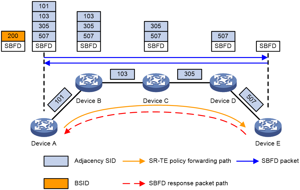
As shown in Figure 5, the SR-MPLS TE policy uses control-packet-mode SBFD to detect the forwarding paths as follows:
1. The source node (Device A) sends an SBFD control packet that encapsulates the candidate path of the highest preference of the SR-MPLS TE policy. If the candidate path of the highest preference in the SR-MPLS TE policy has multiple SID lists, multiple SBFD sessions are established to detect the forwarding path for each SID list.
2. Upon receiving the SBFD packet, the destination node (Device E, the reflector) checks whether the remote discriminator carried the packet is the same as the local discriminator. If they are the same, the reflector sends the response SBFD control packet to the initiator according to the IPv6 routing table. If they are different, the reflector drops the SBFD control packet.
3. Upon receiving the SBFD response, Device A determines that the forwarding path for the SID list is available. If no response is received, Device A determines that the forwarding path is faulty. If all SID lists for the current candidate path are faulty, another candidate path takes over.
The SR-MPLS TE policy uses echo-packet-mode SBFD to detect the forwarding paths as follows:
1. The source node (Device A) sends an SBFD echo packet that encapsulates the candidate path of the highest preference of the SR-MPLS TE policy. If the candidate path of the highest preference in the SR-MPLS TE policy has multiple SID lists, multiple SBFD sessions are established to detect the forwarding path for each SID list.
2. Upon receiving the SBFD echo packet, the destination node (Device E) sends the packet back along the shortest path obtained through routing table lookup.
3. Upon receiving the SBFD echo packet from Device E before the detection timer expires, Device A determines that the forwarding path for the SID list is available. If no response is received, Device A determines that the forwarding path is faulty. If all SID lists for the current candidate path are faulty, another candidate path takes over.
Restrictions and guidelines
You can enable SBFD for all SR-MPLS TE policies globally in SR TE view or for a specific SR-MPLS TE policy in SR-MPLS TE policy view. The policy-specific configuration takes precedence over the global configuration. An SR-MPLS TE policy uses the global configuration only when it has no policy-specific configuration.
Because SBFD response packets are forwarded according to routing table lookup, all SBFD sessions for the SR-MPLS TE policies that have the same source and destination nodes use the same path to send responses. A failure of the SBFD response path will cause all the SBFD sessions to be down and consequentially all the SR-MPLS TE policies go down.
You cannot enable echo SBFD for SR-MPLS TE policies with endpoint IPv6 addresses.
If both SBFD and echo BFD are enabled for an SR-MPLS TE policy, the device first establishes the SBFD session.
If both echo SBFD and echo BFD are enabled for an SR-MPLS TE policy, the device first establishes the echo SBFD session.
When informing SBFD to establish an SBFD session, the SR-MPLS TE policy sends the source and destination IP addresses of the packet to SBFD. The SR-MPLS TE policy selects the source IP address as follows:
1. The source IP address specified by the source-address command.
2. The source IP address specified by the mpls lsr-id or sbfd source-ipv6 command.
To configure SR-MPLS TE policy detection, make sure the reflector has a route to the source IP address of the SBFD packets sent by the initiator.
For more information about the commands configured in segment routing view, see SR-MPLS TE policy commands in Segment Routing Command Reference.
Prerequisites
Before configuring the initiator for SR-MPLS TE policy detection, you must first use the mpls bfd enable command to enable BFD for MPLS. For more information about the mpls bfd enable command, see MPLS OAM commands in MPLS Command Reference.
Configuring control-packet-mode SBFD to detect SR-MPLS TE policies (with IPv4 endpoints)
1. Enter system view.
system-view
2. (Optional.) Associate the destination IPv4 address of the detected path with the remote discriminator of the SBFD session for the initiator.
sbfd destination ipv4 destination-ipv4-address remote-discriminator { ipv4-address | integer-value }
By default, the destination IPv4 address of the detected path is not associated with the remote discriminator of the SBFD session for the initiator.
Configure this command if you want to specify the remote discriminator for establishing SBFD sessions.
3. Enter segment routing view.
segment-routing
4. Enter SR TE view.
traffic-engineering
5. Enable SBFD for all SR-MPLS TE policies.
sr-policy sbfd enable [ proxy-reflector ] [ remote remote-id ] [ template template-name ] [ backup-template backup-template-name ]
By default, SBFD is disabled for all SR-MPLS TE policies.
6. (Optional.) Configure SBFD detection timer parameters.
sr-policy sbfd timer { detect-multiplier multiplier-value | min-tx-interval transmit-interval }
By default, no SBFD detection timer parameters are configured.
7. Enter SR-MPLS TE policy view.
policy policy-name
8. (Optional.) Configure the source IP address for SBFD packets to detect the SR-MPLS TE policy.
source-address ipv4 ipv4-address
By default, no source IP address is configured for SBFD packets to detect an SR-MPLS TE policy.
If you do not configure this command, SBFD uses the IP address specified by the mpls lsr-id command as the source IP address for SBFD packets to detect the SR-MPLS TE policy.
9. Configure SBFD for the SR-MPLS TE policy.
sbfd { disable | enable [ proxy-reflector [ disable ] ] [ remote remote-id ] [ template template-name ] [ backup-template backup-template-name ] }
By default, SBFD is not configured for an SR-MPLS TE policy, and the configuration in SR TE view takes effect.
Configuring control-packet-mode SBFD to detect SR-MPLS TE policies (with IPv6 endpoints and IPv4 encapsulation for SBFD packets)
1. Enter system view.
system-view
2. Enter segment routing view.
segment-routing
3. Enter SR TE view.
traffic-engineering
4. Enable SBFD for all SR-MPLS TE policies.
sr-policy sbfd enable encapsulation-mode ipv4 [ proxy-reflector ] [ remote remote-id ] [ template template-name ] [ backup-template backup-template-name ]
By default, SBFD is disabled for all SR-MPLS TE policies.
5. (Optional.) Configure SBFD detection timer parameters.
sr-policy sbfd timer { detect-multiplier multiplier-value | min-tx-interval transmit-interval }
By default, no SBFD detection timer parameters are configured.
6. Enter SR-MPLS TE policy view.
policy policy-name
7. (Optional.) Configure the source IP address for SBFD packets to detect the SR-MPLS TE policy.
source-address ipv4 ipv4-address
By default, no source IP address is configured for SBFD packets to detect an SR-MPLS TE policy.
If you do not configure this command, SBFD uses the IP address specified by the mpls lsr-id command as the source IP address for SBFD packets to detect the SR-MPLS TE policy.
8. Configure SBFD for the SR-MPLS TE policy.
sbfd { disable | enable [ encapsulation-mode ipv4 ] [ proxy-reflector [ disable ] ] [ remote remote-id ] [ template template-name ] [ backup-template backup-template-name ] }
By default, SBFD is not configured for an SR-MPLS TE policy, and the configuration in SR TE view takes effect.
Configuring control-packet-mode SBFD to detect SR-MPLS TE policies (with IPv6 endpoint and IPv6 encapsulation for SBFD packets)
1. Enter system view.
system-view
2. Specify the source IPv6 address used by the initiator to send SBFD control packets.
sbfd source-ipv6 ipv6-address
By default, no source IPv6 address is specified for SBFD control packets.
3. Enter segment routing view.
segment-routing
4. Enter SR TE view.
traffic-engineering
5. Enable SBFD for all SR-MPLS TE policies.
sr-policy sbfd enable [ encapsulation-mode ipv6 ] [ proxy-reflector ] [ remote remote-id ] [ template template-name ] [ backup-template backup-template-name ]
By default, SBFD is disabled for all SR-MPLS TE policies.
6. (Optional.) Configure SBFD detection timer parameters.
sr-policy sbfd timer { detect-multiplier multiplier-value | min-tx-interval transmit-interval }
By default, no SBFD detection timer parameters are configured.
7. Enter SR-MPLS TE policy view.
policy policy-name
8. (Optional.) Configure the source IP address for SBFD packets to detect the SR-MPLS TE policy.
source-address ipv6 ipv6-address
By default, no source IP address is configured for SBFD packets to detect an SR-MPLS TE policy.
9. Configure SBFD for the SR-MPLS TE policy.
sbfd { disable | enable [ encapsulation-mode ipv6 ] [ proxy-reflector [ disable ] ] [ remote remote-id ] [ template template-name ] [ backup-template backup-template-name ] }
By default, SBFD is not configured for an SR-MPLS TE policy, and the configuration in SR TE view takes effect.
Configuring echo-packet-mode SBFD to detect SR-MPLS TE policies (with IPv4 endpoints)
1. Enter system view.
system-view
2. Enter segment routing view.
segment-routing
3. Enter SR TE view.
traffic-engineering
4. Enable SBFD for all SR-MPLS TE policies.
sr-policy sbfd echo enable [ template template-name ] [ backup-template backup-template-name ]
By default, SBFD is disabled for all SR-MPLS TE policies.
5. (Optional.) Configure SBFD detection timer parameters.
sr-policy sbfd timer { detect-multiplier multiplier-value | min-tx-interval transmit-interval }
By default, no SBFD detection timer parameters are configured.
6. Enter SR-MPLS TE policy view.
policy policy-name
7. (Optional.) Configure the source IP address for SBFD packets to detect the SR-MPLS TE policy.
source-address ipv4 ipv4-address
By default, no source IP address is configured for SBFD packets to detect an SR-MPLS TE policy.
If you do not configure this command, SBFD uses the IP address specified by the mpls lsr-id command as the source IP address for SBFD packets to detect the SR-MPLS TE policy.
8. Configure SBFD for the SR-MPLS TE policy.
sbfd echo { disable | enable [ template template-name ] [ backup-template backup-template-name ] }
By default, SBFD is not configured for an SR-MPLS TE policy, and the configuration in SR TE view takes effect.
Configuring the initiator for SRv6 locator detection
About this task
When the peer CE is dual-homed to two PEs in public network IP over SRv6 BE, IP L3VPN over SRv6 BE, or EVPN L3VPN over SRv6 BE, the local PE generates a primary path and a backup path after you enable FRR on it. To quickly detect failures and forward traffic through the backup path when the primary path fails, you can configure SBFD to detect the SRv6 locator routes advertised through BGP by the peer PE.
SBFD detects the connectivity of the SRv6 locator network segment advertised through BGP in the following process:
1. The local PE (the initiator) sends a SBFD packet. The source IP address is the IP address specified by the sbfd source-ipv6 command and the destination IP address is the SRv6 locator.
2. Upon receiving the SBFD packet, the peer PE (the reflector) checks whether the remote discriminator carried in the packet is the same as the local discriminator. If they are the same, the reflector sends the response SBFD control packet to the initiator according to the IPv6 routing table. If they are different, the reflector drops the SBFD control packet.
3. If the initiator receives the SBFD response packet before the detection time expires, it considers the SRv6 locator available. Otherwise, the backup path takes over.
Restrictions and guidelines
For this function to take effect, perform the following tasks:
· Execute the sbfd destination ipv6 remote-discriminator command on the local PE to specify the remote discriminator for an SBFD session to detect the SRv6 locator.
· Execute the sbfd local-discriminator command on the peer PE of the primary path to specify the local discriminator for the reflector.
· Make sure the remote discriminator on the local PE is consistent with the local discriminator on the peer PE.
For more information about commands in SRv6 view, see SRv6 commands in Segment Routing Command Reference.
Procedure
1. Enter system view.
system-view
2. Specify the source IPv6 address used by the initiator to send SBFD control packets.
sbfd source-ipv6 ipv6-address
By default, no source IPv6 address is specified for SBFD control packets.
3. Enter SRv6 view.
segment-routing ipv6
4. Configure SBFD for SRv6 locators.
locator-sbfd enable [ template template-name ] [ prefix-list prefix-list-name ]
By default, SBFD is not configured for SRv6 locators.
Configuring the initiator for SRv6 TE policy detection
About this task
SBFD can detect the connectivity of an SRv6 TE policy and provide millisecond-level fault detection and fast fault switchover. In an SRv6 TE policy, the candidate path with the greatest preference value acts as the primary path and that with the second greatest preference value acts as the backup path. SBFD detects both primary and backup paths and all SID lists of each path. If all the SID lists for the primary path are faulty, SBFD triggers a primary-to-back path switchover.
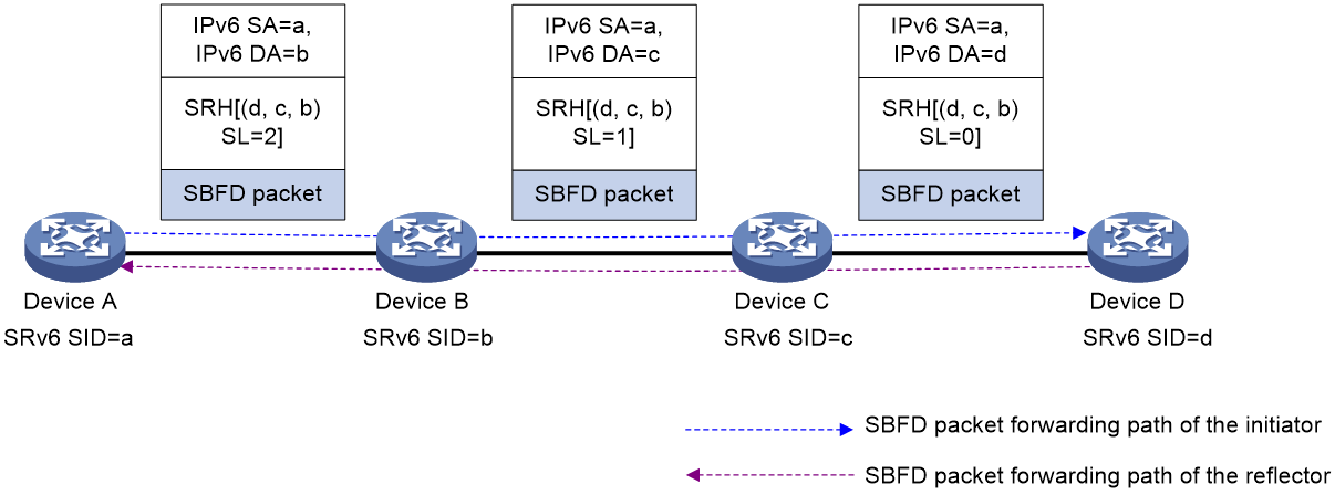
As shown in Figure 6, configure an SRv6 TE policy on Device A and use SBFD to detect the SRv6 TE policy. The detection process is as follows:
1. The source node (Device A, the initiator) sends SBFD control packets that encapsulate the SID lists of the primary and backup candidate paths of the SRv6 TE policy.
2. After the destination node (Device D, the reflector) receives an SBFD control packet, it checks whether the remote discriminator carried the packet is the same as the local discriminator. If they are the same, the reflector sends the response SBFD control packet to the initiator according to the IPv6 routing table. If they are different, the reflector drops the SBFD control packet.
3. If the source node receives the response SBFD control packet before the detection time expires, it considers the corresponding SID list (forwarding path) of the SRv6 TE policy available. Otherwise, the device considers the SID list faulty. If all the SID lists for the primary path are faulty, SBFD triggers a primary-to-back path switchover.
Figure 6 SRv6 TE policy association with SBFD
Restrictions and guidelines
You can enable SBFD for all SRv6 TE policies globally in SRv6 TE view or for a specific SRv6 TE policy in SRv6 TE policy view. The policy-specific configuration takes precedence over the global configuration. An SRv6 TE policy uses the global configuration only when it has no policy-specific configuration.
When informing SBFD to establish an SBFD session, the SRv6 TE policy sends the source and destination IP addresses of the packet to SBFD. The SRv6 TE policy selects the source IP address as follows:
1. The source IP address specified by the source-address command.
2. The source IP address specified by the sbfd source-ipv6 or sbfd source-ipv4 command.
To configure SRv6 TE policy detection, make sure the reflector has a route to the source IP address of the SBFD packets sent by the initiator.
For more information about the commands configured in SRv6 view, see SRv6 TE policy commands in Segment Routing Command Reference.
Procedure
1. Enter system view.
system-view
2. (Optional.) Associate the destination IPv6 address of the detected path with the remote discriminator of the SBFD session for the initiator.
sbfd destination ipv4 destination-ipv4-address remote-discriminator { ipv4-address | integer-value }
By default, the destination IPv6 address of the detected path is not associated with the remote discriminator of the SBFD session for the initiator.
If you do not specify the remote discriminator for the SBFD session with the sbfd or srv6-policy sbfd command, you must configure the sbfd destination ipv6 remote-discriminator command. Without the configuration, the SBFD session cannot come up.
3. (Optional.) Set the detection time multiplier.
bfd multi-hop detect-multiplier value
The default setting is 5.
4. (Optional.) Set the minimum interval for sending SBFD control packets.
bfd multi-hop min-transmit-interval interval
The default setting is 400 milliseconds.
5. Specify the source IPv6 address used by the initiator to send SBFD packets.
sbfd source-ipv6 ipv6-address
By default, no source IPv6 address is specified for the initiator to send SBFD packets.
6. Specify the source IPv4 address used by the initiator to send SBFD packets (when the endpoint of the SRv6 TE policy has an IPv4 address).
sbfd source-ipv4 ipv4-address
By default, no source IPv4 address is specified for the initiator to send SBFD packets.
7. Enter SRv6 view.
segment-routing ipv6
8. Enter SRv6 TE view.
traffic-engineering
9. Enable SBFD for all SRv6 TE policies and configure the SBFD session parameters.
srv6-policy sbfd [ remote remote-id ] [ template template-name ] [ backup-template backup-template-name ]
By default, SBFD is disabled for all SRv6 TE policies.
10. Enter SRv6 TE policy view.
policy policy-name
11. (Optional.) Configure the source IP address for SBFD packets to detect the SRv6 TE policy.
source-address { ip ipv4-address | ipv6 ipv6-address }
By default, no source IP address is configured for SBFD packets to detect an SRv6 TE policy.
12. Configure SBFD for the SRv6 TE policy.
sbfd { disable | enable [ remote remote-id ] [ template template-name ] [ backup-template backup-template-name ] [ oam-sid sid ] [ encaps | insert [ no-endpoint ] ] }
By default, SBFD is not configured for an SRv6 TE policy.
For more information about this command, see SRv6 TE policy commands in Segment Routing Command Reference.
Configuring the reflector
Restrictions and guidelines
If you configure an IPv4 address as the local discriminator, the device automatically converts it to an integer. Configure an IPv4 address local discriminator only when it is required for interoperation with a third-party device.
The reflector replies with a response SBFD control packet only when the remote discriminator in the SBFD control packet sent from the initiator is specified in the sbfd local-discriminator command.
Procedure
1. Enter system view.
system-view
2. Configure a local discriminator.
sbfd local-discriminator { ipv4-address | integer-value }
By default, no local discriminator is configured.
You can execute this command multiple times to configure multiple local discriminators.
Configuring a BFD template
About this task
You can configure SBFD parameters for the following paths through a BFD template:
· LDP LSPs.
· MPLS TE tunnels.
· SR-MPLS TE policies.
· SRv6 TE policies.
Procedure
1. Enter system view.
system-view
2. Create a BFD template and enter BFD template view.
bfd template template-name
3. Set the detection time multiplier.
bfd detect-multiplier value
The default setting is 5.
4. Set the minimum interval for sending SBFD control packets.
bfd min-transmit-interval interval
The default setting is 400 milliseconds.
Delaying session negotiation for down SBFD sessions
About this task
If an upper-layer protocol uses SBFD to detect the active path, an active/standby path switchover is triggered after the active path goes down. If the SBFD session comes up before the active path recovers, the traffic on the standby path will be switched over to the active path. In this case, traffic loss will occur.
The session negotiation delay function starts a delay timer for each SBFD session when it changes from up to down state and each newly created session. Before the timer expires, the device does not perform session negotiation for the session. The delay timer allows the active path to recover completely before the SBFD session comes up again.
Restrictions and guidelines
This feature is supported only in R5212 and later versions.
Procedure
1. Enter system view.
system-view
2. Enable session negotiation delay for down SBFD sessions and set a delay timer.
bfd session-negotiation delay-upon-down interval
By default, session negotiation delay is disabled for down SBFD sessions.
Dynamically modifying the port number of BFD packets
About this task
When you use BFD to detect link connectivity between two devices that have multiple available paths (for example, ECMP or aggregate links) between them, the device selects the path for forwarding BFD packets based on the UDP port number. By default, for a specific BFD session, the source port number of BFD packets is randomly generated upon session startup and then keeps unchanged. The destination port number is determined based on the session type, and keeps unchanged during the session.
As a result, the device always uses the same path to forward BFD packets. When the path fails, the BFD session goes down. The network redundancy capabilities are not fully utilized, which might affect the accuracy of link connectivity detection and stability of the network. You can use this feature to resolve the previous issues.
When you use BFD to detect link connectivity between two devices, configure the command based on the session mode as follows:
· For a BFD session in control packet mode, configure this command on both devices.
· For a BFD session in echo packet mode, configure this command on only the device that sends echo packets.
This command enables the device to modify the port number of BFD packets. The device can then select different paths to forward BFD packets, avoiding the BFD session down issue upon a single link failure. The device modifies the port number as follows:
· For BFD packets, the device modifies the source port number of the packets.
· For SBFD packets, the initiator modifies the source port number of the packets, and the reflector modifies the destination port number of the packets.
Restrictions and guidelines
This feature is a proprietary implementation by H3C. As a best practice, do not use this feature in the scenarios where H3C devices collaborate with devices from other vendors. If you do so, BFD session flapping might occur.
This command takes effect only on hardware BFD sessions. This command takes effect on both existing BFD sessions and newly created BFD sessions.
This command takes effect on both BFD and SBFD packets.
Procedure
1. Enter system view.
system-view
2. Enable dynamic modification for the port number of BFD packets.
bfd dynamic-udp-port enable
By default, dynamic modification for the port number of BFD packets is disabled.
Verifying and maintaining SBFD
To display SBFD session information, execute the following command in any view:
display sbfd session { initiator [ discriminator value | [ ipv6 [ peer-ipv6 ipv6-address ] | srv6-policy ] [ verbose ] | verbose ] | reflector [ discriminator value | verbose ] }
