- Table of Contents
-
- 17-High Availability Configuration Guide
- 00-Preface
- 01-Ethernet OAM configuration
- 02-CFD configuration
- 03-DLDP configuration
- 04-ERPS configuration
- 05-Smart Link configuration
- 06-Monitor Link configuration
- 07-S-Trunk configuration
- 08-Error code detection configuration
- 09-VRRP configuration
- 10-BFD configuration
- 11-Track configuration
- 12-Process placement configuration
- 13-Interface collaboration configuration
- Related Documents
-
| Title | Size | Download |
|---|---|---|
| 09-VRRP configuration | 719.45 KB |
Virtual IP address and IP address owner
Router priority in a VRRP group
Virtual MAC address assignment
Restrictions and guidelines: IPv4 VRRP configuration
Specifying an IPv4 VRRP operating mode
Specifying the IPv4 VRRP version
Configuring an IPv4 VRRP group
Configuring a subordinate IPv4 VRRP group to follow a master IPv4 VRRP group
Associating an IPv4 VRRP group with a track entry
Enabling the preemptive mode for the router in a VRRP group and setting the preemption delay timer
Specifying an IPv4 VRRP control VLAN
Configuring IPv4 VRRP packet attributes
Setting the packet sending mode for IPv4 VRRPv3
Enabling periodic sending of gratuitous ARP packets for IPv4 VRRP
Setting the state transition delay timer for an IPv4 VRRP group
Enabling an IPv4 VRRP group to ignore interface down events
Enabling SNMP notifications for VRRP
Enabling the isolation mode for IPv4 VRRP
Verifying and maintaining IPv4 VRRP
Restrictions and guidelines: IPv6 VRRP configuration
Specifying an IPv6 VRRP operating mode
Configuring an IPv6 VRRP group
Configuring a subordinate IPv6 VRRP group to follow a master IPv6 VRRP group
Associating an IPv6 VRRP group with a track entry
Specifying an IPv6 VRRP control VLAN
Configuring IPv6 VRRP packet attributes
Enabling periodic sending of ND packets for IPv6 VRRP
Setting the state transition delay timer for an IPv6 VRRP group
Enabling an IPv6 VRRP group to ignore interface down events
Enabling the isolation mode for IPv6 VRRP
Verifying and maintaining IPv6 VRRP
IPv4 VRRP configuration examples
Example: Configuring a single VRRP group
Example: Configuring multiple VRRP groups
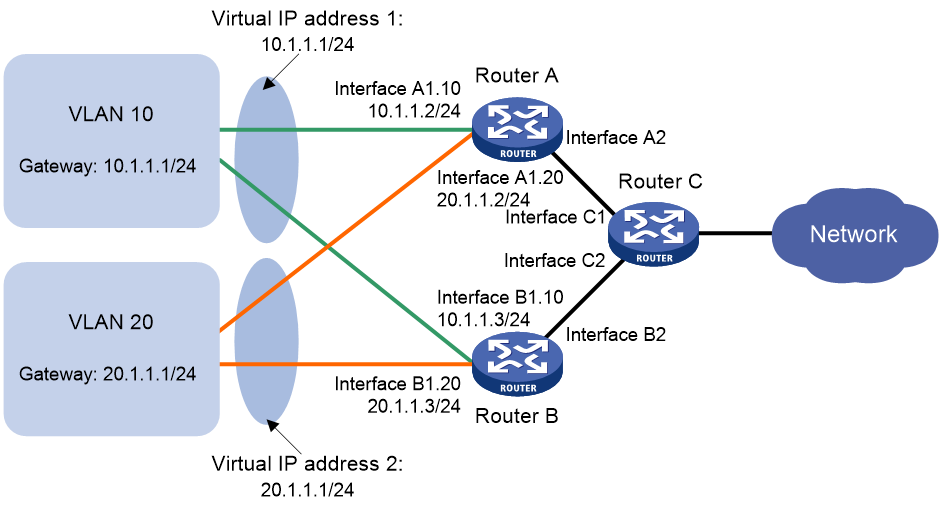
Example: Configuring VRRP load balancing
IPv6 VRRP configuration examples
Example: Configuring a single VRRP group
Example: Configuring multiple VRRP groups
Example: Configuring VRRP load balancing
Configuring VRRP
About VRRP
Typically, you can configure a default gateway for every host on a LAN. All packets destined for other networks are sent through the default gateway. As shown in Figure 1, when the default gateway fails, no hosts can communicate with external networks.
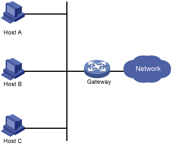
Using a default gateway facilitates your configuration but requires high availability. Using more egress gateways improves link availability but introduces the problem of routing among the egresses.
Virtual Router Redundancy Protocol (VRRP) is designed to address this issue. VRRP adds a group of network gateways to a VRRP group called a virtual router. The VRRP group has one master and multiple backups, and provides a virtual IP address. The hosts on the subnet use the virtual IP address as their default network gateway to communicate with external networks.
VRRP avoids single points of failure and simplifies the configuration on hosts. When the master in the VRRP group on a multicast or broadcast LAN (for example, an Ethernet network) fails, another router in the VRRP group takes over. The switchover is complete without causing dynamic route recalculation, route re-discovery, gateway reconfiguration on the hosts, or traffic interruption.
VRRP operates in either of the following modes:
· Standard mode—Implemented based on RFCs. For more information, see "VRRP standard mode."
· Load balancing mode—Extends the VRRP standard mode to distribute load across VRRP group members. For more information, see "VRRP load balancing mode."
VRRP has two versions: VRRPv2 and VRRPv3. VRRPv2 supports IPv4 VRRP. VRRPv3 supports IPv4 VRRP and IPv6 VRRP.
VRRP standard mode
VRRP networking
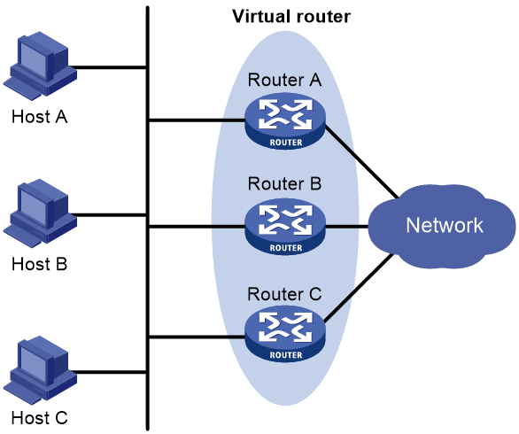
As shown in Figure 2, Router A, Router B, and Router C form a virtual router, which has its own IP address. Hosts on the subnet use the virtual router as the default gateway.
The router with the highest priority among the three routers is elected as the master, and the other two are backups. Only the master in the VRRP group can provide gateway service. When the master fails, the backup routers elect a new master to take over for nonstop gateway service.
Virtual IP address and IP address owner
The virtual IP address of the virtual router can be either of the following IP addresses:
· Unused IP address on the subnet where the VRRP group resides.
· IP address of an interface on a router in the VRRP group.
In the latter case, the router is called the IP address owner. A VRRP group can have only one IP address owner.
Router priority in a VRRP group
VRRP determines the role (master or backup) of each router in a VRRP group by priority. A router with higher priority is more likely to become the master.
A VRRP priority can be in the range of 0 to 255, and a greater number represents a higher priority. Priorities 1 to 254 are configurable. Priority 0 is reserved for special uses, and priority 255 is for the IP address owner. The IP address owner in a VRRP group always has a running priority of 255 and acts as the master as long as it operates correctly.
Preemption
A router in a VRRP group operates in either non-preemptive mode or preemptive mode.
· Non-preemptive mode—The master router acts as the master as long as it operates correctly, even if a backup router is later assigned a higher priority. Non-preemptive mode helps avoid frequent switchover between the master and backup routers.
· Preemptive mode—A backup starts a new master election and takes over as master when it detects that it has a higher priority than the current master. Preemptive mode ensures that the router with the highest priority in a VRRP group always acts as the master.
Authentication method
To avoid attacks from unauthorized users, VRRP member routers add authentication keys in VRRP packets to authenticate one another. VRRP provides the following authentication methods:
· Simple authentication
The sender fills an authentication key into the VRRP packet, and the receiver compares the received authentication key with its local authentication key. If the two authentication keys match, the received VRRP packet is legitimate. Otherwise, the received packet is illegitimate and gets discarded.
· MD5 authentication
The sender computes a digest for the VRRP packet by using the authentication key and MD5 algorithm, and saves the result to the packet. The receiver performs the same operation with the authentication key and MD5 algorithm, and compares the result with the content in the authentication header. If the results match, the received VRRP packet is legitimate. Otherwise, the received packet is illegitimate and gets discarded.
On a secure network, you can choose to not authenticate VRRP packets.
|
|
NOTE: IPv4 VRRPv3 and IPv6 VRRPv3 do not support VRRP packet authentication. |
VRRP timers
Skew_Time
Skew_Time helps avoid the situation that multiple backups in a VRRP group become the master when the master in the VRRP group fails.
Skew_Time is not configurable; its value depends on the VRRP version.
· In VRRPv2 (described in RFC 3768), Skew_Time is (256 – Router priority)/256.
· In VRRPv3 (described in RFC 5798), Skew_Time is ((256 – Router priority) × VRRP advertisement interval)/256.
VRRP advertisement interval
The master in a VRRP group periodically sends VRRP advertisements to declare its presence.
You can configure the interval at which the master sends VRRP advertisements. If a backup does not receive any VRRP advertisement when the timer (3 × VRRP advertisement interval + Skew_Time) expires, it takes over as the master.
VRRP preemption delay timer
You can configure the VRRP preemption delay timer for the following purposes:
· Avoid frequent state changes among members in a VRRP group.
· Provide the backups with enough time to collect information (such as routing information).
In preempt mode, a backup does not immediately become the master after it receives an advertisement with lower priority than the local priority. Instead, it waits for a period of time (preemption delay time + Skew_Time) before taking over as the master.
Master election
Routers in a VRRP group determine their roles by priority. When a router joins a VRRP group, it has a backup role. The router role changes according to the following situations:
· If the backup does not receive any VRRP advertisement when the timer (3 × advertisement interval + Skew_Time) expires, it becomes the master.
· If the backup receives a VRRP advertisement with the same or greater priority within the timer (3 × advertisement interval + Skew_Time), it remains a backup.
· If the backup receives a VRRP advertisement with a smaller priority within the timer (3 × advertisement interval + Skew_Time), the following results apply:
¡ It remains a backup when operating in non-preemptive mode.
¡ It becomes the master when operating in preemptive mode.
The elected master starts a VRRP advertisement interval to periodically send VRRP advertisements to notify the backups that it is operating correctly. Each of the backups starts a timer to wait for advertisements from the master.
When multiple routers in a VRRP group declare that they are the master because of network problems, the one with the highest priority becomes the master. If two routers have the same priority, the one with the highest IP address becomes the master.
VRRP tracking
The VRRP tracking function uses network quality analyzer (NQA) or bidirectional forwarding detection (BFD) to monitor the state of the master or the upstream link. The collaboration between VRRP and NQA or BFD through a track entry implements the following functions:
· Monitors the upstream link and changes the priority of the router according to the state of the link. If the upstream link fails, the hosts on the subnet cannot access external networks through the router and the state of the track entry becomes Negative. The priority of the master decreases by a specified value, and a router with a higher priority in the VRRP group becomes the master. The switchover ensures uninterrupted communication between the hosts on the subnet and external networks.
· Monitors the state of the master on the backups. When the master fails, a backup immediately takes over to ensure uninterrupted communication.
When the track entry changes from Negative to Positive or Notready, the router automatically restores its priority. For more information about track entries, see "Configuring Track."
To enable VRRP tracking, configure the routers in the VRRP group to operate in preemptive mode first. This configuration ensures that only the router with the highest priority operates as the master.
VRRP application
Master/backup
In master/backup mode, only the master forwards packets, as shown in Figure 3. When the master fails, a new master is elected from among the backups. This mode requires only one VRRP group, and each router in the group has a different priority. The one with the highest priority becomes the master.
Figure 3 VRRP in master/backup mode
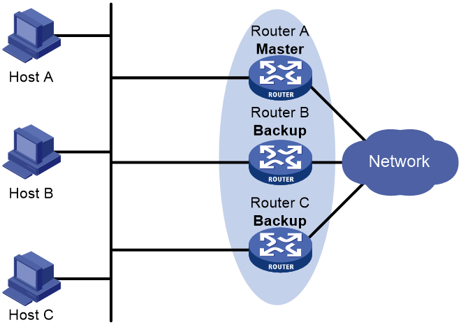
Assume that Router A is acting as the master to forward packets to external networks, and Router B and Router C are backups in listening state. When Router A fails, Router B and Router C elect a new master to forward packets for hosts on the subnet.
Load sharing
A router can join multiple VRRP groups. With different priorities in different VRRP groups, the router can act as the master in one VRRP group and a backup in another.
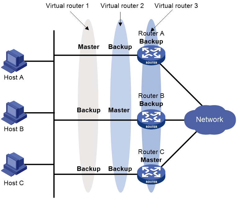
In load sharing mode, multiple VRRP groups provide gateway services. This mode requires a minimum of two VRRP groups, and each group has one master and multiple backups. The master roles in the VRRP groups are assumed by different routers, as shown in Figure 4.
A router can be in multiple VRRP groups and have a different priority in each group.
As shown in Figure 4, the following VRRP groups exist:
· VRRP group 1—Router A is the master. Router B and Router C are the backups.
· VRRP group 2—Router B is the master. Router A and Router C are the backups.
· VRRP group 3—Router C is the master. Router A and Router B are the backups.
To implement load sharing among Router A, Router B, and Router C, perform the following tasks:
· Configure the virtual IP addresses of VRRP group 1, 2, and 3 as default gateway IP addresses for hosts on the subnet.
· Assign the highest priority to Router A, B, and C in VRRP group 1, 2, and 3, respectively.
VRRP load balancing mode
In a standard-mode VRRP group, only the master can forward packets and backups are in listening state. You can create multiple VRRP groups to share traffic, but you must configure different gateways for hosts on the subnet.
In load balancing mode, a VRRP group maps its virtual IP address to multiple virtual MAC addresses, assigning one virtual MAC address to each member router. Every router in this VRRP group can forward traffic and respond to IPv4 ARP requests or IPv6 ND requests from hosts. Because their virtual MAC addresses are different, traffic from hosts is distributed across the VRRP group members. Load balancing mode simplifies configuration and improves forwarding efficiency.
VRRP load balancing mode uses the same master election, preemption, and tracking mechanisms as the standard mode. New mechanisms have been introduced to VRRP load balancing mode, as described in the following sections.
Virtual MAC address assignment
In load balancing mode, the master assigns virtual MAC addresses to routers in the VRRP group. The master uses different MAC addresses to respond to ARP requests or ND requests from different hosts. The backup routers, however, do not answer ARP requests or ND requests from hosts.
In an IPv4 network, a load balanced VRRP group works as follows:
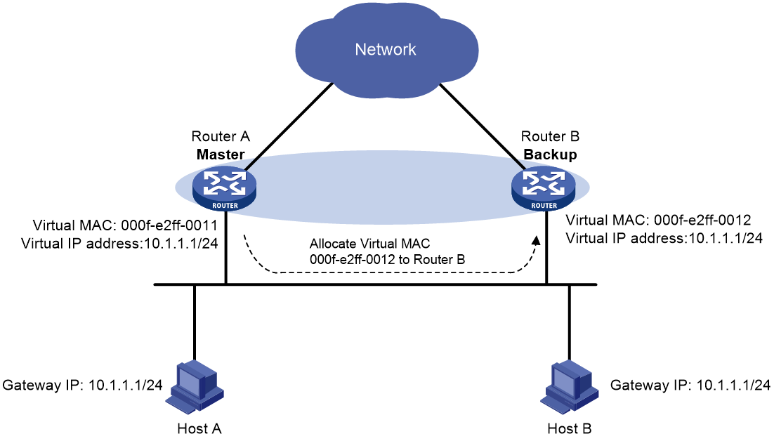
1. The master assigns virtual MAC addresses to all member routers, including itself. This example assumes that the virtual IP address of the VRRP group is 10.1.1.1/24, Router A is the master, and Router B is the backup. Router A assigns 000f-e2ff-0011 for itself and 000f-e2ff-0012 for Router B. See Figure 5.
Figure 5 Virtual MAC address assignment
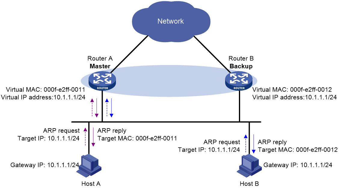
2. When an ARP request arrives, the master (Router A) selects a virtual MAC address based on the load balancing algorithm to answer the ARP request. In this example, Router A returns the virtual MAC address of itself in response to the ARP request from Host A. Router A returns the virtual MAC address of Router B in response to the ARP request from Host B. See Figure 6.
Figure 6 Answering ARP requests
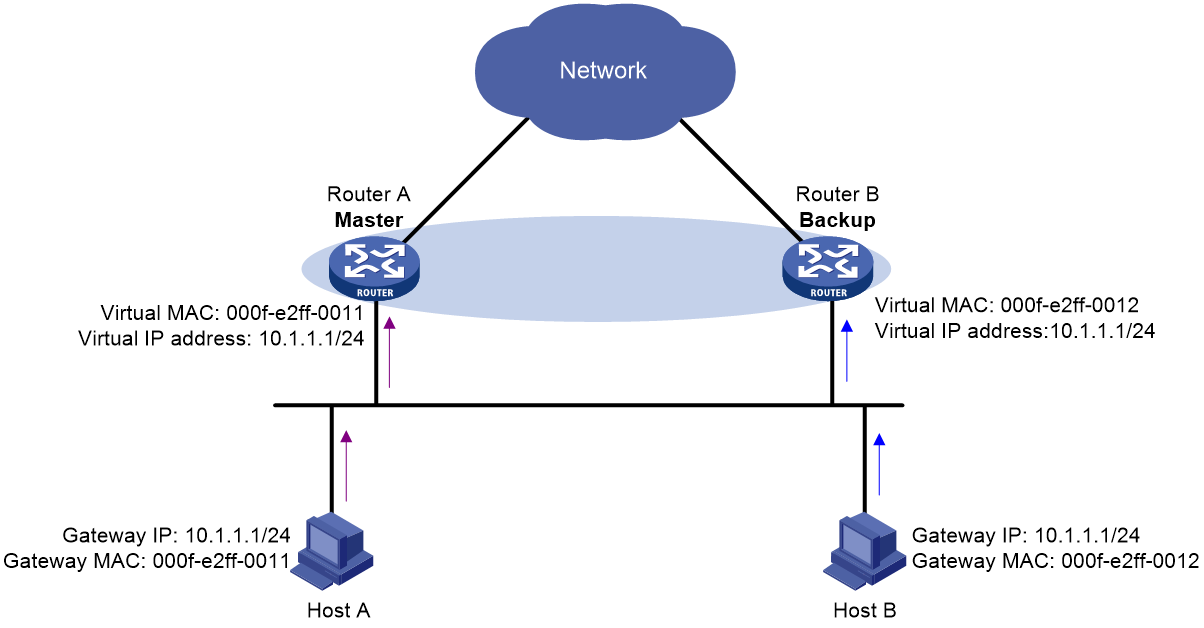
3. Each host sends packets to the returned MAC address. As shown in Figure 7, Host A sends packets to Router A and Host B sends packets to Router B.
Figure 7 Sending packets to different routers for forwarding
In the ARP reply sent by the master, the source MAC address in the Ethernet header is different from the sender MAC address in the message body. For the Layer 2 device to forward the ARP packet, follow these configuration guidelines on the Layer 2 device:
· Do not enable ARP packet source MAC address consistency check.
· Do not specify the src-mac keyword when you enable ARP packet validity check for ARP detection.
For more information about ARP packet source MAC address consistency check and ARP detection, see Security Configuration Guide.
Virtual forwarder
Virtual forwarder creation
Virtual MAC addresses enable traffic distribution across routers in a VRRP group. To enable routers in the VRRP group to forward packets, VFs must be created on them. Each VF is associated with a virtual MAC address in the VRRP group and forwards packets that are sent to this virtual MAC address.
VFs are created on routers in a VRRP group, as follows:
1. The master assigns virtual MAC addresses to all routers in the VRRP group. Each member router creates a VF for this MAC address and becomes the owner of this VF.
2. Each VF owner advertises its VF information to the other member routers.
3. After receiving the VF advertisement, each of the other routers creates the advertised VF.
Eventually, every member router maintains one VF for each virtual MAC address in the VRRP group.
VF weight and priority
The weight of a VF indicates the forwarding capability of a VF. A higher weight means higher forwarding capability. When the weight is lower than the lower limit of failure, the VF cannot forward packets.
The priority of a VF determines the VF state. Among the VFs created on different member routers for the same virtual MAC address, the VF with the highest priority is in active state. This VF, known as the active virtual forwarder (AVF), forwards packets. All other VFs listen to the state of the AVF and are known as the listening virtual forwarders (LVFs). VF priority is in the range of 0 to 255, where 255 is reserved for the VF owner. When the weight of a VF owner is higher than or equal to the lower limit of failure, the priority of the VF owner is 255.
The priority of a VF is calculated based on its weight.
· If the VF weight is higher than or equal to the lower limit of failure, the following VF priorities apply:
¡ On a VF owner, the VF priority is 255.
¡ On a non-VF owner, the VF priority is calculated as weight/(number of local AVFs + 1).
· If the VF weight is lower than the lower limit of failure, the VF priority is 0.
VF backup
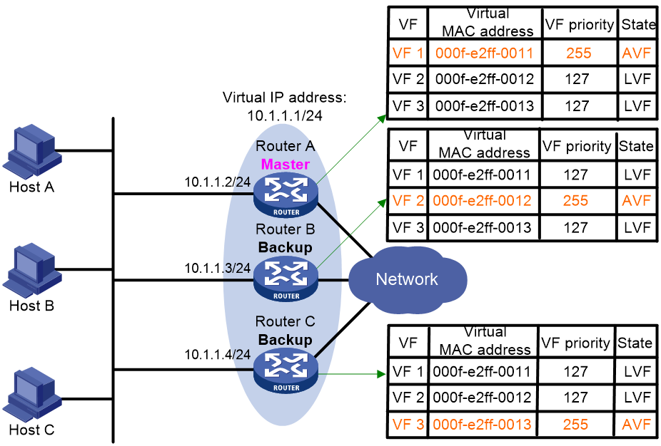
Figure 8 shows the VF table on each router in the VRRP group and how the VFs back up one another. The master, Router A, assigns virtual MAC addresses 000f-e2ff-0011, 000f-e2ff-0012, and 000f-e2ff-0013 to itself, Router B, and Router C, respectively. Each router creates VF 1, VF 2, and VF 3 for virtual MAC addresses 000f-e2ff-0011, 000f-e2ff-0012, and 000f-e2ff-0013, respectively. The VFs for the same virtual MAC address on different routers back up one another. For example, the VF 1 instances on Router A, Router B, and Router C back up one another.
· The VF 1 instances on Router B and Router C have a priority of 255/(1 + 1), or 127. Because their priorities are lower than the priority of the VF 1 instance on Router A, they act as LVFs. These LVFs listen to the state of the VF 1 instance on Router A.
· When the VF 1 instance on Router A fails, the VF 1 instances on Router B and Router C elect the one with higher priority as the new AVF. This AVF forwards packets destined for virtual MAC address 000f-e2ff-0011. If the two LVFs' priorities are the same, the LVF with a greater device MAC address becomes the new AVF.
A VF always operates in preemptive mode. When an LVF finds its priority value higher than the one advertised by the AVF, the LVF declares itself as the AVF.
VF timers
When the AVF on a router fails, the new AVF on another router creates the following timers for the failed AVF:
· Redirect timer—Before this timer expires, the master still uses the virtual MAC address corresponding to the failed AVF to respond to ARP/ND requests from hosts. The VF owner can share traffic load if the VF owner resumes normal operation within this time. When this timer expires, the master stops using the virtual MAC address corresponding to the failed AVF to respond to ARP/ND requests from hosts.
· Timeout timer—The duration after which the new AVF takes over responsibilities of the failed VF owner. Before this timer expires, all routers in the VRRP group keep the VFs that correspond to the failed AVF. The new AVF forwards packets destined for the virtual MAC address of the failed AVF. When this timer expires, all routers in the VRRP group remove the VFs that correspond to the failed AVF, including the new AVF. Packets destined for the virtual MAC address of the failed AVF are not forwarded any longer.
VF tracking
An AVF forwards packets destined for the MAC address of the AVF. If the AVF's upstream link fails but no LVF takes over, the hosts that use the AVF's MAC address as their gateway MAC address cannot access the external network.
The VF tracking function can solve this problem. You can use NQA or BFD to monitor the upstream link state of the VF owner, and associate the VFs with NQA or BFD through the tracking function. This enables the collaboration between VRRP and NQA or BFD through the Track module. When the upstream link fails, the state of the track entry changes to Negative. The weights of the VFs (including the AVF) on the router decrease by a specific value. The corresponding LVF with a higher priority on another router becomes the AVF and forwards packets.
Protocols and standards
· RFC 3768, Virtual Router Redundancy Protocol (VRRP)
· RFC 5798, Virtual Router Redundancy Protocol (VRRP) Version 3 for IPv4 and IPv6
Configuring IPv4 VRRP
Restrictions and guidelines: IPv4 VRRP configuration
· IPv4 VRRP does not take effect on member ports of aggregation groups.
· Configuration on the routers in an IPv4 VRRP group must be consistent.
IPv4 VRRP tasks at a glance
To configure IPv4 VRRP, perform the following tasks:
1. Specifying an IPv4 VRRP operating mode
2. (Optional.) Specifying the IPv4 VRRP version
3. Configuring an IPv4 VRRP group
4. (Optional.) Configuring a subordinate IPv4 VRRP group to follow a master IPv4 VRRP group
5. (Optional.) Associating an IPv4 VRRP group with a track entry
This configuration takes effect only in VRRP load balancing mode.
6. (Optional.) Enabling the preemptive mode for the router in a VRRP group and setting the preemption delay timer
7. (Optional.) Configuring IPv4 VRRP packet attributes
8. (Optional.) Setting the packet sending mode for IPv4 VRRPv3
9. (Optional.) Enabling periodic sending of gratuitous ARP packets for IPv4 VRRP
10. (Optional.) Setting the state transition delay timer for an IPv4 VRRP group
11. (Optional.) Enabling an IPv4 VRRP group to ignore interface down events
12. (Optional.) Enabling SNMP notifications for VRRP
13. (Optional.) Enabling the isolation mode for IPv4 VRRP
14. (Optional.) Disabling an IPv4 VRRP group
Specifying an IPv4 VRRP operating mode
Restrictions and guidelines
After an IPv4 VRRP operating mode is configured on a router, all IPv4 VRRP groups on the router operate in the specified operating mode.
Procedure
1. Enter system view.
system-view
2. Specify an IPv4 VRRP operating mode.
¡ Specify the standard mode.
undo vrrp mode
¡ Specify the load balancing mode.
vrrp mode load-balance [ version-8 ]
By default, VRRP operates in standard mode.
Specifying the IPv4 VRRP version
About this task
IPv4 VRRP can use VRRPv2 and VRRPv3.
Restrictions and guidelines
For an IPv4 VRRP group to operate correctly, make sure the same VRRP version is used on all routers in the IPv4 VRRP group.
Procedure
1. Enter system view.
system-view
2. Enter interface view.
interface interface-type interface-number
3. Specify the version of VRRP.
vrrp version version-number
By default, VRRPv3 is used.
Configuring an IPv4 VRRP group
About this task
A VRRP group can operate correctly after you create it and assign a minimum of one virtual IP address to it. You can configure multiple virtual IP addresses for the VRRP group on an interface that connects to multiple subnets for router backup on different subnets.
If you disable an IPv4 VRRP group, the VRRP group enters Initialize state, and the existing configuration on the VRRP group remains unchanged. You can modify the configuration of the VRRP group. The modification takes effect when you enable the VRRP group again.
Restrictions and guidelines
|
Item |
Remarks |
|
VLAN interface |
Do not create a VRRP group on the VLAN interface of a super VLAN because network performance might be adversely affected. For information about the super VLAN feature, see Layer 2—LAN Switching Configuration Guide. |
|
Maximum number of VRRP groups and virtual IP addresses |
In VRRP load balancing mode, the device supports a maximum of MaxVRNum/N VRRP groups. MaxVRNum refers to the maximum number of VRRP groups supported by the device in VRRP standard mode. N refers to the number of devices in the VRRP group. |
|
Virtual IP address |
When VRRP is operating in standard mode, the virtual IP address of a VRRP group can be either of the following addresses: · Unused IP address on the subnet where the VRRP group resides. · IP address of an interface on a router in the VRRP group. In load balancing mode, the virtual IP address of a VRRP group can be any unassigned IP address of the subnet where the VRRP group resides. It cannot be the IP address of any interfaces in the VRRP group. No IP address owner can exist in a VRRP group. An IPv4 VRRP group without virtual IP addresses configured can exist on a device provided that other settings (for example, priority and preemption mode) are available. Such a VRRP group stays in inactive state and does not function. For hosts in the subnet to access external networks, as a best practice, configure the following addresses in the same subnet: · Virtual IP address of an IPv4 VRRP group. · Downlink interface IP addresses of the VRRP group members. |
|
IP address owner |
On an IP address owner, as a best practice, do not use the network command to enable OSPF on the interface owning the virtual IP address of the VRRP group. For more information about the network command, see Layer 3—IP Routing Command Reference. After you remove the VRRP group on an IP address owner, a backup in the VRRP group takes over as the master. The actual IP address of the interface on the IP address owner will conflict with the virtual IP address of the new master. To avoid the conflict, change the IP address of the interface on the IP address owner before you remove the VRRP group from the interface. The running priority of an IP address owner is always 255, and you do not need to configure it. An IP address owner always operates in preemptive mode. If you configure the vrrp vrid track priority reduced or vrrp vrid track switchover command on an IP address owner, the configuration does not take effect until the router becomes a non-IP address owner. |
Creating a VRRP group and assigning a virtual IP address
1. Enter system view.
system-view
2. Enter interface view.
interface interface-type interface-number
3. Create a VRRP group and assign a virtual IP address.
vrrp vrid virtual-router-id virtual-ip virtual-address
4. Set the priority of the router in the VRRP group.
vrrp vrid virtual-router-id priority priority-value
The default setting is 100.
Configuring a subordinate IPv4 VRRP group to follow a master IPv4 VRRP group
About this task
Each VRRP group determines the device role (master or backup) by exchanging VRRP packets among member devices, which might consume excessive bandwidth and CPU resources. To reduce the number of VRRP packets in the network, you can configure a subordinate VRRP group to follow a master VRRP group.
A master VRRP group determines the device role through exchanging VRRP packets among member devices. A VRRP group that follows a master group, called a subordinate VRRP group, does not exchange VRRP packets among its member devices. The state of the subordinate VRRP group follows the state of the master group.
Restrictions and guidelines
· To ensure the master router election, configure the settings such as the router priority, preemptive mode, and tracking function for the master IPv4 VRRP group. The settings are not required for subordinate IPv4 VRRP groups.
· You can configure a subordinate VRRP group to follow a master VRRP group in both VRRP standard and load balancing modes. The configuration takes effect only in VRRP standard mode.
· An IPv4 VRRP group cannot be both a master group and a subordinate group.
· An IPv4 VRRP group stays in Inactive state if it is configured to follow a nonexistent master group.
· If an IPv4 VRRP group in Inactive or Initialize state follows a master group that is not in Inactive state, the state of the VRRP group does not change.
· A subordinate IPv4 VRRP group does not exchange VRRP packets, which might cause the MAC address entry for its virtual MAC address not to be updated on downstream devices. As a best practice, enable periodic sending of gratuitous ARP packets for IPv4 VRRP by using the vrrp send-gratuitous-arp command.
· You can associate a VRRP group with a maximum of one of the following objects:
¡ Master VRRP group.
¡ Track.
¡ HA group.
¡ Cluster traffic group.
Procedure
1. Enter system view.
system-view
2. Enter interface view.
interface interface-type interface-number
3. Configure an IPv4 VRRP group as a master group and assign a name to it.
vrrp vrid virtual-router-id name name
By default, an IPv4 VRRP group does not act as a master group.
4. Return to system view.
quit
5. Enter interface view.
interface interface-type interface-number
6. Configure an IPv4 VRRP group to follow a master group.
vrrp vrid virtual-router-id follow name
By default, an IPv4 VRRP group does not follow a master VRRP group.
Associating an IPv4 VRRP group with a track entry
About this task
You can configure this function in both standard mode and load balancing mode, but the function takes effect only in load balancing mode.
In load balancing mode, you can establish the collaboration between the VFs and NQA or BFD through the tracking function. When the state of the track entry transits to Negative, the weights of all VFs in the VRRP group on the router decrease by a specific value. When the state of the track entry transits to Positive or Notready, the original weight values of the VFs restore.
Restrictions and guidelines
· By default, the weight of a VF is 255, and its lower limit of failure is 10.
· When the weight of a VF owner is higher than or equal to the lower limit of failure, its priority is always 255. The priority does not change with the weight. When the upstream link of the VF owner fails, an LVF must take over as the AVF. The switchover happens when the weight of the VF owner drops below the lower limit of failure. This requires that the reduced weight for the VF owner be higher than 245.
· You can associate a VRRP group with a maximum of one of the following objects:
¡ Master VRRP group.
¡ Track.
¡ HA group.
¡ Cluster traffic group.
Procedure
1. Enter system view.
system-view
2. Enter interface view.
interface interface-type interface-number
3. Associate an IPv4 VRRP group or the VFs in an IPv4 VRRP group with a track entry.
vrrp vrid virtual-router-id track track-entry-number { forwarder-switchover member-ip ip-address | priority reduced [ priority-reduced ] | switchover | weight reduced [ weight-reduced ] }
By default, an IPv4 VRRP group is not associated with any track entries.
Enabling the preemptive mode for the router in a VRRP group and setting the preemption delay timer
About this task
In preemptive mode, a backup sends VRRP advertisements when it detects that it has a higher priority than the master. Then the backup takes over as the master and the previous master becomes a backup.
Procedure
1. Enter system view.
system-view
2. Enter interface view.
interface interface-type interface-number
3. Enable the preemptive mode for the router in a VRRP group and set the preemption delay timer.
vrrp vrid virtual-router-id preempt-mode [ delay delay-value ]
By default, the router in a VRRP group operates in preemptive mode and the preemption delay time is 0 centiseconds.
Specifying an IPv4 VRRP control VLAN
About this task
As shown in Figure 9, ambiguous VLAN termination is configured for VLAN 10 and VLAN 20 on the Layer 3 Ethernet subinterfaces on routers. To allow the master to regularly send VRRP advertisements in multicast to the backups, enable the VLAN termination-enabled subinterfaces to transmit broadcast packets and multicast packets. Then, the master can send VRRP advertisements within all VLANs whose VLAN packets are configured to be terminated by the subinterfaces. If ambiguous VLAN termination is configured on the Layer 3 Ethernet subinterfaces for a large range of VLANs, the VRRP advertisements might overload the subinterfaces. This adversely affects the performance of the routers.
To resolve this problem, you can disable the VLAN termination-enabled subinterfaces from transmitting broadcast packets and multicast packets and configure a VRRP control VLAN. The master sends VRRP advertisements only within the control VLAN.
Specify VRRP control VLANs according to the VLAN termination type.
· For ambiguous Dot1q termination, specify one control VLAN by the outermost layer of VLAN tag.
· For ambiguous QinQ termination, specify two control VLANs by the outermost two layers of VLAN tags.
For more information about VLAN termination, see Layer 2—LAN Switching Configuration Guide.
Restrictions and guidelines
· When VRRP is operating in load balancing mode, you cannot specify the VRRP control VLAN.
· As a best practice, configure the arp send-gratuitous-arp command on the routers in a VRRP group after you specify a VRRP control VLAN. This command enables the routers to periodically send gratuitous ARP packets. The devices in the VLAN terminated ambiguously can then update MAC address entries after a master switchover. For more information about the arp send-gratuitous-arp command, see Layer 3—IP Services Command Reference.
Procedure
1. Enter system view.
system-view
2. Enter Layer 3 Ethernet subinterface view or Layer 3 RPR logical interface view.
interface interface-type interface-number
3. Specify VRRP control VLANs.
¡ Specify a VRRP control VLAN for the ambiguous Dot1q termination-enabled subinterface.
vrrp dot1q vid vlan-id
¡ Specify VRRP control VLANs for the ambiguous QinQ termination-enabled subinterface.
vrrp dot1q vid vlan-id secondary-dot1q secondary-vlan-id
By default, no VRRP control VLAN is specified. The master sends VRRP advertisements within all VLANs whose VLAN packets are configured to be terminated by the subinterface.
Configuring IPv4 VRRP packet attributes
Restrictions and guidelines
· You can configure different authentication modes and authentication keys for VRRP groups on an interface. However, members of the same VRRP group must use the same authentication mode and authentication key.
· In VRRPv3, authentication mode and authentication key settings do not take effect.
· In a VRRPv2 group, the VRRP advertisement intervals on all routers must be either greater than 1 second or no greater than 1 second.
¡ If the VRRP advertisement intervals are greater than 1 second, the routers in the VRRP group must have the same VRRP advertisement interval. The master re-election delay timer for the backups is 3 × advertisement interval of the master + Skew_Time.
¡ If the VRRP advertisement intervals are no greater than 1 second, the routers in the VRRP group can have different VRRP advertisement intervals. The VRRP advertisement interval for the master must be smaller than the master re-election delay timer for any backups. The master re-election timer for a backup is 3 × advertisement interval for the backup + Skew_Time. As a best practice, configure the same VRRP advertisement interval for all routers in the VRRP group.
Procedure
1. Enter system view.
system-view
2. Enter interface view.
interface interface-type interface-number
3. Configure the authentication mode and authentication key for an IPv4 VRRP group to send and receive VRRP packets.
vrrp vrid virtual-router-id authentication-mode { md5 | simple } { cipher | plain } string
By default, authentication is disabled.
4. Set the interval at which the master in an IPv4 VRRP group sends VRRP advertisements.
vrrp vrid virtual-router-id timer advertise { adver-interval | msec milliseconds-adver-interval }
The default setting is 100 centiseconds.
The msec milliseconds-adver-interval option takes effect only for VRRPv2. For VRRPv3, the default interval (1 second) applies regardless of the value configured for this option.
5. Specify the source interface for receiving and sending VRRP packets.
vrrp vrid virtual-router-id source-interface interface-type interface-number
By default, the source interface for receiving and sending VRRP packets is not specified. The interface where the VRRP group resides sends and receives VRRP packets.
6. Enable TTL check for IPv4 VRRP packets.
vrrp check-ttl enable
By default, TTL check for IPv4 VRRP packets is enabled.
7. Return to system view.
quit
8. Set a DSCP value for VRRP packets.
vrrp dscp dscp-value
By default, the DSCP value for VRRP packets is 48.
The DSCP value identifies the packet priority during transmission.
Setting the packet sending mode for IPv4 VRRPv3
About this task
A router configured with VRRPv3 can process incoming VRRPv2 packets, but a router configured with VRRPv2 cannot process incoming VRRPv3 packets. When the VRRP version of the routers in a VRRP group is changed from VRRPv2 to VRRPv3, multiple masters might be elected in the VRRP group. To resolve the problem, you can set the packet sending mode for IPv4 VRRPv3. This task enables a router configured with VRRPv3 to send VRRPv2 packets and communicate with routers configured with VRRPv2.
Restrictions and guidelines
· The packet sending mode for IPv4 VRRPv3 takes effect only on outgoing VRRP packets. A router configured with VRRPv3 can process incoming VRRPv2 and VRRPv3 packets.
· If you set the packet sending mode for IPv4 VRRPv3 and configure VRRP packet authentication, authentication information will be carried in outgoing VRRPv2 packets but not in outgoing VRRPv3 packets.
· The VRRP advertisement interval is set in centiseconds by using the vrrp vrid timer advertise command. The VRRP advertisement interval carried in VRRPv2 packets sent from routers configured with VRRPv3 might be different from the configured value. For information about the VRRP advertisement interval, see the vrrp vrid timer advertise command in High Availability Command Reference.
Procedure
1. Enter system view.
system-view
2. Enter interface view.
interface interface-type interface-number
3. Set the packet sending mode for IPv4 VRRPv3.
vrrp vrid virtual-router-id vrrpv3-send-packet { v2-only | v2v3-both }
By default, a router configured with VRRPv3 sends only VRRPv3 packets.
Enabling periodic sending of gratuitous ARP packets for IPv4 VRRP
About this task
This feature enables the master router in a VRRP group to periodically send gratuitous ARP packets. Then the downstream devices can update the MAC address entry for the virtual MAC address of the VRRP group in a timely manner.
Restrictions and guidelines
· This feature takes effect only in VRRP standard mode.
· If you change the sending interval for gratuitous ARP packets, the configuration takes effect at the next sending interval.
· The master sends the first gratuitous ARP packet at a random time in the second half of the set interval after you execute the vrrp send-gratuitous-arp command. This prevents too many gratuitous ARP packets from being sent at the same time.
· The sending interval for gratuitous ARP packets might be much longer than the set interval when the following conditions are met:
¡ Multiple VRRP groups exist on the device.
¡ A short sending interval is set.
Procedure
1. Enter system view.
system-view
2. Enable periodic sending of gratuitous ARP packets for IPv4 VRRP.
vrrp send-gratuitous-arp [ interval interval ]
By default, periodic sending of gratuitous ARP packets is disabled for IPv4 VRRP.
Setting the state transition delay timer for an IPv4 VRRP group
About this task
Typically, an IPv4 VRRP group immediately transitions from Initialize to Master or Backup state when the interface where the IPv4 VRRP group resides comes up. If the device restarts or the interface state changes frequently, the IPv4 VRRP group state might be unstable, and the VRRP group operation might be affected.This task allows you to solve this issue.
Restrictions and guidelines
The delay time for an IPv4 VRRP group to transition from Initialize to Master or Backup state is in the range of 0 to 60 seconds.
Procedure
1. Enter system view.
system-view
2. Enter interface view.
interface interface-type interface-number
3. Set the state transition delay timer for the IPv4 VRRP group.
vrrp state-transition-delay delay-value
By default, the delay time is 0 seconds for the IPv4 VRRP group to transition from Initialize to Master or Backup state.
Enabling an IPv4 VRRP group to ignore interface down events
About this task
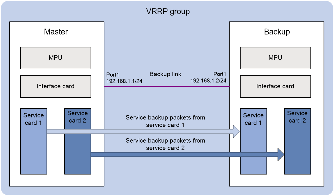
Some high availability services(such as failover group and subordinate VRRP group) determine the device roles based on the device states in the associated VRRP group. The master device corresponds to the master in the VRRP group and is used to forward traffic. The backup device corresponds to the backup in the VRRP group and is used to monitor the state of the master device. If the VRRP group is configured on the interfaces of a direct link connecting two devices, an interface or link failure can cause a state transition. The master and backup in the VRRP group transition to Initialize state. Consequently, the master and backup devices for the associated high availability service transition to the initialized state, and the master device stops processing service data. To prevent interruption of high availability services, perform this task on the two devices in the VRRP group. The VRRP group will keep the state of master and backup unchanged when a hosting interface is physically down.
As shown in Figure 10, in the network where a failover group is bound with a VRRP group, a direct link exists between the two devices. The VRRP group is configured on the interfaces at the two ends of the direct link. The failover group determines the primary node and secondary node based on the device states (master and backup) in the VRRP group. If an interface or link failure occurs, the peer interface physically goes down, and the master and backup in the VRRP group transition to Initialize state. As a result, the primary node in the failover group stops process service data, and a service interruption occurs. To avoid this issue, perform this task to keep the state of master and backup unchanged in the VRRP group upon an interface or link failure.
Figure 10 Networking of a failover group bound with a VRRP group
For more information about master and subordinate IPv4 VRRP groups, see "Configuring a subordinate IPv4 VRRP group to follow a master IPv4 VRRP group."
Procedure
1. Enter system view.
system-view
2. Enter interface view.
interface interface-type interface-number
3. Enable an IPv4 VRRP group to ignore interface down events.
vrrp vrid virtual-router-id ignore-interface-down
By default, an IPv4 VRRP group is disabled from ignoring interface down events.
Enabling SNMP notifications for VRRP
About this task
To report critical VRRP events to an NMS, enable SNMP notifications for VRRP. For VRRP event notifications to be sent correctly, you must also configure SNMP on the device. For more information about SNMP configuration, see the network management and monitoring configuration guide for the device.
Procedure
1. Enter system view.
system-view
2. Enable SNMP notifications for VRRP.
snmp-agent trap enable vrrp [ auth-failure | new-master ]
By default, SNMP notifications for VRRP are enabled.
Enabling the isolation mode for IPv4 VRRP
About this task
To maintain the master in an IPv4 VRRP group, use this feature to perform a master/backup switchover. In isolation mode, the maintenance operation on the device is performed after a master/backup switchover and does not affect services.
Enabling the isolation mode sets the priority of the device to 0 in the IPv4 VRRP group.
Restrictions and guidelines
If you set the priority with the vrrp vrid priority command for a device in isolation mode, the setting does not take effect until the isolation mode is disabled.
Procedure
1. Enter system view.
system-view
2. Enable the isolation mode for IPv4 VRRP.
vrrp isolate enable
By default, the isolation mode is disabled for IPv4 VRRP.
Disabling an IPv4 VRRP group
1. Enter system view.
system-view
2. Enter interface view.
interface interface-type interface-number
3. Disable a VRRP group.
vrrp vrid virtual-router-id shutdown
By default, an IPv4 VRRP group is enabled.
|
|
CAUTION: You can use this command to temporarily disable an IPv4 VRRP group. After you execute this command, packets sent to the IPv4 VRRP group might be discarded. |
Verifying and maintaining IPv4 VRRP
Verifying IPv4 VRRP group configuration and running status
Perform display tasks in any view.
· Display states of IPv4 VRRP groups.
display vrrp [ interface interface-type interface-number [ vrid virtual-router-id ] ] [ verbose ]
· Display master-to-subordinate IPv4 VRRP group bindings.
display vrrp binding [ interface interface-type interface-number [ vrid virtual-router-id ] | name name ]
Displaying and clearing IPv4 VRRP group statistics
To display statistics for IPv4 VRRP groups, execute the following command in any view:
display vrrp statistics [ interface interface-type interface-number [ vrid virtual-router-id ] ]
To clear statistics for IPv4 VRRP groups, execute the following command in user view:
reset vrrp statistics [ interface interface-type interface-number [ vrid virtual-router-id ] ]
Configuring IPv6 VRRP
Restrictions and guidelines: IPv6 VRRP configuration
· IPv6 VRRP does not take effect on member ports of aggregation groups.
· Configuration on the routers in an IPv6 VRRP group must be consistent.
IPv6 VRRP tasks at a glance
To configure IPv6 VRRP, perform the following tasks:
1. Specifying an IPv6 VRRP operating mode
2. Configuring an IPv6 VRRP group
3. (Optional.) Configuring a subordinate IPv6 VRRP group to follow a master IPv6 VRRP group
4. (Optional.) Associating an IPv6 VRRP group with a track entry
This configuration takes effect only in VRRP load balancing mode.
5. (Optional.) Enabling the preemptive mode for the router in an IPv6 VRRP group and setting the preemption delay timer
6. (Optional.) Configuring IPv6 VRRP packet attributes
7. (Optional.) Enabling periodic sending of ND packets for IPv6 VRRP
8. (Optional.) Setting the state transition delay timer for an IPv6 VRRP group
9. (Optional.) Enabling an IPv6 VRRP group to ignore interface down events
10. (Optional.) Enabling the isolation mode for IPv6 VRRP
11. (Optional.) Disabling an IPv6 VRRP group
Specifying an IPv6 VRRP operating mode
Restrictions and guidelines
After the IPv6 VRRP operating mode is specified on a router, all IPv6 VRRP groups on the router operate in the specified operating mode.
Procedure
1. Enter system view.
system-view
2. Specify an IPv6 VRRP operating mode.
¡ Specify the standard mode.
undo vrrp ipv6 mode
¡ Specify the load balancing mode.
vrrp ipv6 mode load-balance
By default, VRRP operates in standard mode.
Configuring an IPv6 VRRP group
About this task
A VRRP group can work correctly after you create it and assign a minimum of one virtual IPv6 address for it. You can configure multiple virtual IPv6 addresses for the VRRP group on an interface that connects to multiple subnets for router backup.
If you disable an IPv6 VRRP group, the VRRP group enters Initialize state, and the existing configuration on the VRRP group remains unchanged. You can modify the configuration of the VRRP group. The modification takes effect when you enable the VRRP group again.
Restrictions and guidelines
|
Item |
Remarks |
|
VLAN interface |
Do not create VRRP groups on the VLAN interface of a super VLAN. Otherwise, network performance might be adversely affected. For information about the super VLAN feature, see Layer 2—LAN Switching Configuration Guide. |
|
Maximum number of VRRP groups and virtual IPv6 addresses |
In VRRP load balancing mode, the device supports a maximum of MaxVRNum/N VRRP groups. MaxVRNum refers to the maximum number of VRRP groups supported by the device in VRRP standard mode. N refers to the number of devices in the VRRP group. |
|
Virtual IPv6 address |
In load balancing mode, the virtual IPv6 address of a VRRP group cannot be the same as the IPv6 address of any interfaces in the VRRP group. No IP address owner can exist in a VRRP group. An IPv6 VRRP group without virtual IPv6 addresses configured can exist on a device provided that other settings (for example, priority and preemption mode) are available. Such a VRRP group stays in inactive state and does not function. For hosts in the subnet to access external networks, as a best practice, configure the following addresses in the same subnet: · Virtual IPv6 address of an IPv6 VRRP group. · Downlink interface IPv6 addresses of the VRRP group members. |
|
IP address owner |
On an IP address owner, as a best practice, do not use the ospfv3 area command to enable OSPF on the interface owning the virtual IPv6 address of the VRRP group. For more information about the ospfv3 area command, see Layer 3—IP Routing Command Reference. After you remove the IPv6 VRRP group on an IP address owner, a backup in the IPv6 VRRP group takes over as the master. The actual IPv6 address of the interface on the IP address owner will conflict with the virtual IPv6 address of the new master. To avoid the conflict, change the IPv6 address of the interface on the IP address owner before you remove the IPv6 VRRP group from the interface. The running priority of an IP address owner is always 255, and you do not need to configure it. An IP address owner always operates in preemptive mode. If you configure the vrrp ipv6 vrid track priority reduced or vrrp ipv6 vrid track switchover command on an IP address owner, the configuration does not take effect until the router becomes a non-IP address owner. On an IP address owner, disable Duplicate Address Detection (DAD) on the interface configured with VRRP. To disable DAD, set the interval argument to 0 for the ipv6 nd dad attempts command. For more information about the command, see IPv6 basics commands in Layer 3—IP Services Command Reference. |
Creating a VRRP group and assign a virtual IPv6 address
1. Enter system view.
system-view
2. Enter interface view.
interface interface-type interface-number
3. Create a VRRP group and assign a virtual IPv6 address, which is a link-local address.
vrrp ipv6 vrid virtual-router-id virtual-ip virtual-address link-local
The first virtual IPv6 address that you assign to an IPv6 VRRP group must be a link-local address. It must be the last address you remove. Only one link-local address is allowed in a VRRP group.
4. Assign a virtual IPv6 address, which is a global unicast address.
vrrp ipv6 vrid virtual-router-id virtual-ip virtual-address
By default, no global unicast address is assigned to an IPv6 VRRP group.
5. Set the priority of the router in the VRRP group.
vrrp ipv6 vrid virtual-router-id priority priority-value
The default setting is 100.
Configuring a subordinate IPv6 VRRP group to follow a master IPv6 VRRP group
About this task
Each IPv6 VRRP group determines the device role (master or backup) by exchanging VRRP packets among member devices, which might consume excessive bandwidth and CPU resources. To reduce the number of VRRP packets in the network, you can configure a subordinate IPv6 VRRP group to follow a master IPv6 VRRP group.
A master IPv6 VRRP group determines the device role through exchanging VRRP packets among member devices. An IPv6 VRRP group that follows a master group, called a subordinate VRRP group, does not exchange VRRP packets among its member devices. The state of the subordinate VRRP group follows the state of the master group.
Restrictions and guidelines
· To ensure the master router election, configure the settings such as the router priority, preemptive mode, and tracking function for the master IPv6 VRRP group. The settings are not required for subordinate IPv6 VRRP groups.
· You can configure a subordinate IPv6 VRRP group to follow a master IPv6 VRRP group in both VRRP standard and load balancing modes. The configuration takes effect only in VRRP standard mode.
· An IPv6 VRRP group cannot be both a master group and a subordinate group.
· An IPv6 VRRP group stays in Inactive state if it is configured to follow a nonexistent master IPv6 VRRP group.
· If an IPv6 VRRP group in Inactive or Initialize state follows a master group that is not in Inactive state, the state of the VRRP group does not change.
· A subordinate IPv6 VRRP group does not exchange VRRP packets, which might cause the MAC address entry for its virtual MAC address not to be updated on downstream devices. As a best practice, enable periodic sending of ND packets for IPv6 VRRP by using the vrrp ipv6 send-nd command.
· You can associate an IPv6 VRRP group with a maximum of one of the following objects:
¡ Master VRRP group.
¡ Track.
¡ HA group.
¡ Cluster traffic group.
Procedure
1. Enter system view.
system-view
2. Enter interface view.
interface interface-type interface-number
3. Configure an IPv6 VRRP group as a master group and assign a name to it.
vrrp ipv6 vrid virtual-router-id name name
By default, an IPv6 VRRP group does not act as a master group.
4. Return to system view.
quit
5. Enter interface view.
interface interface-type interface-number
6. Configure an IPv6 VRRP group to follow a master group.
vrrp ipv6 vrid virtual-router-id follow name
By default, an IPv6 VRRP group does not follow a master VRRP group.
Associating an IPv6 VRRP group with a track entry
About this task
You can configure this function in both standard mode and load balancing mode, but the function takes effect only in load balancing mode.
In load balancing mode, you can configure the VFs in a VRRP group to monitor a track entry. When the state of the track entry transits to Negative, the weights of all VFs in the VRRP group on the router decrease by a specific value. When the state of the track entry transits to Positive or Notready, the original weights of the VFs restore.
Restrictions and guidelines
· By default, the weight of a VF is 255, and its lower limit of failure is 10.
· When the weight of a VF owner is higher than or equal to the lower limit of failure, its priority is always 255. The priority does not change with the weight. When the upstream link of the VF owner fails, an LVF must take over as the AVF. The switchover happens when the weight of the VF owner drops below the lower limit of failure. This requires that the reduced weight for the VF owner be higher than 245.
· You can associate an IPv6 VRRP group with a maximum of one of the following objects:
¡ Master VRRP group.
¡ Track.
¡ HA group.
¡ Cluster traffic group.
Procedure
1. Enter system view.
system-view
2. Enter interface view.
interface interface-type interface-number
3. Associate an IPv6 VRRP group or the VFs in an IPv6 VRRP group with a track entry.
vrrp ipv6 vrid virtual-router-id track track-entry-number { forwarder-switchover member-ip ipv6-address | priority reduced [ priority-reduced ] | switchover | weight reduced [ weight-reduced ] }
By default, an IPv6 VRRP group is not associated with any track entries.
Enabling the preemptive mode for the router in an IPv6 VRRP group and setting the preemption delay timer
About this task
In preemptive mode, a backup sends VRRP advertisements when it detects that it has a higher priority than the master. Then the backup takes over as the master and the previous master becomes a backup.
Procedure
1. Enter system view.
system-view
2. Enter interface view.
interface interface-type interface-number
3. Enable the preemptive mode for the router in an IPv6 VRRP group and set the preemption delay timer.
vrrp ipv6 vrid virtual-router-id preempt-mode [ delay delay-value ]
By default, the router in an IPv6 VRRP group operates in preemptive mode and the preemption delay time is 0 centiseconds.
Specifying an IPv6 VRRP control VLAN
About this task
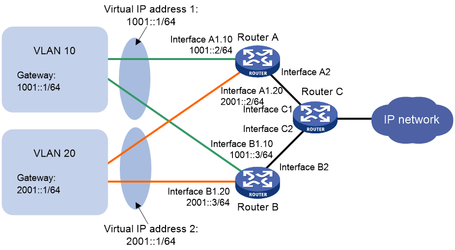
As shown in Figure 11, ambiguous VLAN termination is configured for VLAN 10 and VLAN 20 on the Layer 3 Ethernet subinterfaces on routers. To allow the master to regularly send IPv6 VRRP advertisements in multicast to the backups, enable the VLAN termination-enabled subinterfaces to transmit broadcast packets and multicast packets. Then, the master can send IPv6 VRRP advertisements within all VLANs whose VLAN packets are configured to be terminated by the subinterfaces. If ambiguous VLAN termination is configured on the Layer 3 Ethernet subinterfaces for a large range of VLANs, the IPv6 VRRP advertisements might overload the subinterfaces. This adversely affects the performance of the routers.
To resolve this problem, you can disable the VLAN termination-enabled subinterfaces from transmitting broadcast packets and multicast packets and configure an IPv6 VRRP control VLAN. The master sends IPv6 VRRP advertisements only within the control VLAN.
Figure 11 IPv6 VRRP control VLAN
Specify IPv6 VRRP control VLANs according to the VLAN termination type.
· For ambiguous Dot1q termination, specify one control VLAN by the outermost layer of VLAN tag.
· For ambiguous QinQ termination, specify two control VLANs by the outermost two layers of VLAN tags.
For more information about VLAN termination, see Layer 2—LAN Switching Configuration Guide.
Restrictions and guidelines
When IPv6 VRRP is operating in load balancing mode, you cannot specify the IPv6 VRRP control VLAN.
Procedure
1. Enter system view.
system-view
2. Enter Layer 3 Ethernet subinterface view or Layer 3 RPR logical interface view.
interface interface-type interface-number
3. Specify IPv6 VRRP control VLANs.
¡ Specify an IPv6 VRRP control VLAN for the ambiguous Dot1q termination-enabled subinterface.
vrrp ipv6 dot1q vid vlan-id
¡ Specify IPv6 VRRP control VLANs for the ambiguous QinQ termination-enabled subinterface.
vrrp ipv6 dot1q vid vlan-id secondary-dot1q secondary-vlan-id
By default, no IPv6 VRRP control VLAN is specified. The master sends IPv6 VRRP advertisements within all VLANs whose VLAN packets are configured to be terminated by the subinterface.
Configuring IPv6 VRRP packet attributes
Restrictions and guidelines
· The routers in an IPv6 VRRP group can have different intervals for sending VRRP advertisements. The master in the VRRP group sends VRRP advertisements at the specified interval and carries the interval attribute in the advertisements. After a backup receives the advertisement, it records the interval in the advertisement. If the backup does not receive a VRRP advertisement before the timer (3 x recorded interval + Skew_Time) expires, it regards the master as failed and takes over.
· A high volume of network traffic might cause a backup to fail to receive VRRP advertisements from the master within the specified time. As a result, an unexpected master switchover occurs. To solve this problem, configure a larger interval.
Procedure
1. Enter system view.
system-view
2. Enter interface view.
interface interface-type interface-number
3. Set the IPv6 VRRP advertisement interval.
vrrp ipv6 vrid virtual-router-id timer advertise adver-interval
The default setting is 100 centiseconds.
As a best practice to maintain system stability, set the VRRP advertisement interval to be greater than 100 centiseconds.
4. Return to system view.
quit
5. Set a DSCP value for IPv6 VRRP packets.
vrrp ipv6 dscp dscp-value
By default, the DSCP value for IPv6 VRRP packets is 56.
The DSCP value identifies the packet priority during transmission.
Enabling periodic sending of ND packets for IPv6 VRRP
About this task
This feature enables the master router in an IPv6 VRRP group to periodically send ND packets. Then the downstream devices can update the MAC address entry for the virtual MAC address of the IPv6 VRRP group in a timely manner.
Restrictions and guidelines
· This feature takes effect only in VRRP standard mode.
· If you change the sending interval for ND packets, the configuration takes effect at the next sending interval.
· The master sends the first ND packet at a random time in the second half of the set interval after you execute the vrrp ipv6 send-nd command. This prevents too many ND packets from being sent at the same time.
· The sending interval for ND packets might be much longer than the set interval when the following conditions are met:
¡ Multiple IPv6 VRRP groups exist on the device.
¡ A short sending interval is set.
Procedure
1. Enter system view.
system-view
2. Enable periodic sending of ND packets for IPv6 VRRP.
vrrp ipv6 send-nd [ interval interval ]
By default, periodic sending of ND packets is disabled for IPv6 VRRP.
Setting the state transition delay timer for an IPv6 VRRP group
About this task
Typically, an IPv6 VRRP group immediately transitions from Initialize to Master or Backup state when the interface where the IPv6 VRRP group resides comes up. If the device restarts or the interface state changes frequently, the IPv6 VRRP group state might be unstable, and the VRRP group operation might be affected.This task allows you to solve this issue.
Restrictions and guidelines
The delay time for an IPv6 VRRP group to transition from Initialize to Master or Backup state is in the range of 0 to 60 seconds.
Procedure
1. Enter system view.
system-view
2. Enter interface view.
interface interface-type interface-number
3. Set the state transition delay timer for the IPv6 VRRP group.
vrrp ipv6 state-transition-delay delay-value
By default, the delay time is 0 seconds for the IPv6 VRRP group to transition from Initialize to Master or Backup state.
Enabling an IPv6 VRRP group to ignore interface down events
About this task
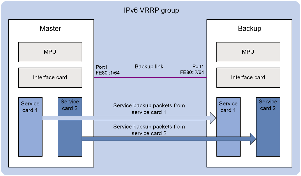
Some high availability services (such as failover group and subordinate IPv6 VRRP group) determine the device roles based on the device states in the associated IPv6 VRRP group. The master device corresponds to the master in the IPv6 VRRP group and is used to forward traffic. The backup device corresponds to the backup in the IPv6 VRRP group and is used to monitor the state of the master device. If the IPv6 VRRP group is configured on the interfaces of a direct link connecting two devices, an interface or link failure can cause a state transition. The master and backup in the IPv6 VRRP group transition to Initialize state. Consequently, the master and backup devices for the associated high availability service transition to the initialized state, and the master device stops processing service data. To prevent interruption of high availability services, perform this task on the two devices in the IPv6 VRRP group. The IPv6 VRRP group will keep the state of master and backup unchanged when a hosting interface is physically down.
As shown in Figure 12, in the network where a failover group is bound with an IPv6 VRRP group, a direct link exists between the two devices. The IPv6 VRRP group is configured on the interfaces at the two ends of the direct link. The failover group determines the primary node and secondary node based on the device states (master and backup) in the IPv6 VRRP group. If an interface or link failure occurs, the peer interface physically goes down, and the master and backup in the IPv6 VRRP group transition to Initialize state. As a result, the primary node in the failover group stops process service data, and a service interruption occurs. To avoid this issue, perform this task to keep the state of master and backup unchanged in the IPv6 VRRP group upon an interface or link failure.
Figure 12 Networking of a failover group bound with an IPv6 VRRP group
For more information about master and subordinate IPv6 VRRP groups, see "Configuring a subordinate IPv6 VRRP group to follow a master IPv6 VRRP group."
Procedure
1. Enter system view.
system-view
2. Enter interface view.
interface interface-type interface-number
3. Enable an IPv6 VRRP group to ignore interface down events.
vrrp ipv6 vrid virtual-router-id ignore-interface-down
By default, an IPv6 VRRP group is disabled from ignoring interface down events.
Enabling the isolation mode for IPv6 VRRP
About this task
To maintain the master in an IPv6 VRRP group, use this feature to perform a master/backup switchover. In isolation mode, the maintenance operation on the device is performed after a master/backup switchover and does not affect services.
Enabling the isolation mode sets the priority of the device to 0 in the IPv6 VRRP group.
Restrictions and guidelines
If you set the priority with the vrrp ipv6 vrid priority command for a device in isolation mode, the setting does not take effect until the isolation mode is disabled.
Procedure
1. Enter system view.
system-view
2. Enable the isolation mode for IPv6 VRRP.
vrrp ipv6 isolate enable
By default, the isolation mode is disabled for IPv6 VRRP.
Disabling an IPv6 VRRP group
1. Enter system view.
system-view
2. Enter interface view.
interface interface-type interface-number
3. Disable an IPv6 VRRP group.
vrrp ipv6 vrid virtual-router-id shutdown
By default, an IPv6 VRRP group is enabled.
|
|
CAUTION: You can use this command to temporarily disable an IPv6 VRRP group. After you execute this command, packets sent to the IPv6 VRRP group might be discarded. |
Verifying and maintaining IPv6 VRRP
Verifying IPv6 VRRP group configuration and running status
Perform display tasks in any view.
· Display the states of IPv6 VRRP groups.
display vrrp ipv6 [ interface interface-type interface-number [ vrid virtual-router-id ] ] [ verbose ]
· Display master-to-subordinate IPv6 VRRP group bindings.
display vrrp ipv6 binding [ interface interface-type interface-number [ vrid virtual-router-id ] | name name ]
Displaying and clearing IPv6 VRRP group statistics
To display statistics for IPv6 VRRP groups, execute the following command in any view:
display vrrp ipv6 statistics [ interface interface-type interface-number [ vrid virtual-router-id ] ]
To clear statistics for IPv6 VRRP groups, execute the following command in user view:
reset vrrp ipv6 statistics [ interface interface-type interface-number [ vrid virtual-router-id ] ]
IPv4 VRRP configuration examples
Example: Configuring a single VRRP group
Network configuration
As shown in Figure 13, Router A and Router B form a VRRP group. They use the virtual IP address 10.1.1.111/24 to provide gateway service for the subnet where Host A resides.
Router A operates as the master to forward packets from Host A to Host B. When Router A fails, Router B takes over to forward packets for Host A.
Configure Router A to operate in preempt mode so Router A can forward traffic as long as Router A operates correctly. Set the preemption delay to 5000 centiseconds to avoid frequent status change.

Prerequisites
By default, interfaces on the device are disabled (in ADM or Administratively Down state). To have an interface operate, you must use the undo shutdown command to enable that interface.
Procedure
1. Configure Router A:
# Specify an IP address for Router A.
<RouterA> system-view
[RouterA] interface hundredgige 1/0/1
[RouterA-HundredGigE1/0/1] ip address 10.1.1.1 255.255.255.0
# Create VRRP group 1 on GigabitEthernet 1/0/1 and set its virtual IP address to 10.1.1.111.
[RouterA-HundredGigE1/0/1] vrrp vrid 1 virtual-ip 10.1.1.111
# Assign Router A a higher priority than Router B in VRRP group 1, so Router A can become the master.
[RouterA-HundredGigE1/0/1] vrrp vrid 1 priority 110
# Configure Router A to operate in preemptive mode, so it can become the master whenever it operates correctly. Set the preemption delay to 5000 centiseconds to avoid frequent status switchover.
[RouterA-HundredGigE1/0/1] vrrp vrid 1 preempt-mode delay 5000
2. Configure Router B:
# Specify an IP address for Router A.
<RouterB> system-view
[RouterB] interface hundredgige 1/0/1
[RouterB-HundredGigE1/0/1] ip address 10.1.1.2 255.255.255.0
# Create VRRP group 1 on GigabitEthernet 1/0/1 and set its virtual IP address to 10.1.1.111.
[RouterB-HundredGigE1/0/1] vrrp vrid 1 virtual-ip 10.1.1.111
# Set the priority of Router B to 100 in VRRP group 1.
[RouterB-HundredGigE1/0/1] vrrp vrid 1 priority 100
# Configure Router B to operate in preemptive mode, and set the preemption delay to 5000 centiseconds.
[RouterB-HundredGigE1/0/1] vrrp vrid 1 preempt-mode delay 5000
Verifying the configuration
# Ping Host B from Host A. (Details not shown.)
# Display detailed information about VRRP group 1 on Router A.
[RouterA-HundredGigE1/0/1] display vrrp verbose
IPv4 virtual router information:
Running mode : Standard
Total number of virtual routers : 1
Interface HundredGigE1/0/1
VRID : 1 Adver timer : 100 centiseconds
Admin status : Up State : Master
Config pri : 110 Running pri : 110
Preempt mode : Yes Delay time : 5000 centiseconds
Auth type : Not supported
Version : 3
Virtual IP : 10.1.1.111
Virtual MAC : 0000-5e00-0101
Master IP : 10.1.1.1
# Display detailed information about VRRP group 1 on Router B.
[RouterB-HundredGigE1/0/1] display vrrp verbose
IPv4 virtual router information:
Running mode : Standard
Total number of virtual routers : 1
Interface HundredGigE1/0/1
VRID : 1 Adver timer : 100 centiseconds
Admin status : Up State : Backup
Config pri : 100 Running pri : 100
Preempt mode : Yes Delay time : 5000 centiseconds
Become master : 412 milliseconds left
Auth type : Not supported
Version : 3
Virtual IP : 10.1.1.111
Master IP : 10.1.1.1
The output shows that Router A is operating as the master in VRRP group 1 to forward packets from Host A to Host B.
# Disconnect the link between Host A and Router A, and verify that Host A can still ping Host B. (Details not shown.)
# Display detailed information about VRRP group 1 on Router B.
[RouterB-HundredGigE1/0/1] display vrrp verbose
IPv4 virtual router information:
Running mode : Standard
Total number of virtual routers : 1
Interface HundredGigE1/0/1
VRID : 1 Adver timer : 100 centiseconds
Admin status : Up State : Master
Config pri : 100 Running pri : 100
Preempt mode : Yes Delay time : 5000 centiseconds
Auth type : Not supported
Version : 3
Virtual IP : 10.1.1.111
Virtual MAC : 0000-5e00-0101
Master IP : 10.1.1.2
The output shows that when Router A fails, Router B takes over to forward packets from Host A to Host B.
# Recover the link between Host A and Router A, and display detailed information about VRRP group 1 on Router A.
[RouterA-HundredGigE1/0/1] display vrrp verbose
IPv4 virtual router information:
Running mode : Standard
Total number of virtual routers : 1
Interface HundredGigE1/0/1
VRID : 1 Adver timer : 100 centiseconds
Admin status : Up State : Master
Config pri : 110 Running pri : 110
Preempt mode : Yes Delay time : 5000 centiseconds
Auth type : Not supported
Version : 3
Virtual IP : 10.1.1.111
Virtual MAC : 0000-5e00-0101
Master IP : 10.1.1.1
The output shows that after Router A resumes normal operation, it becomes the master to forward packets from Host A to Host B.
Example: Configuring multiple VRRP groups
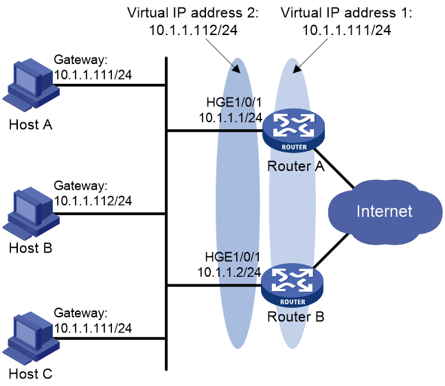
Network configuration
As shown in Figure 14, Router A and Router B form two VRRP groups to implement load sharing and mutual backup. VRRP group 1 uses the virtual IP address 10.1.1.111/24 to provide gateway service for some hosts on the subnet 10.1.1.0/24. VRRP group 2 uses the virtual IP address 10.1.1.112/24 to provide gateway service for the other hosts on the subnet.
Prerequisites
By default, interfaces on the device are disabled (in ADM or Administratively Down state). To have an interface operate, you must use the undo shutdown command to enable that interface.
To implement load sharing between the VRRP groups, manually configure the default gateway 10.1.1.111 or 10.1.1.112 for the hosts on the subnet 10.1.1.0/24.
Procedure
1. Configure Router A:
# Specify an IP address for Router A.
<RouterA> system-view
[RouterA] interface hundredgige 1/0/1
[RouterA-HundredGigE1/0/1] ip address 10.1.1.1 255.255.255.0
# Create VRRP group 1 and set its virtual IP address to 10.1.1.111.
[RouterA-HundredGigE1/0/1] vrrp vrid 1 virtual-ip 10.1.1.111
# Assign Router A a higher priority than Router B in VRRP group 1, so Router A can become the master in the group.
[RouterA-HundredGigE1/0/1] vrrp vrid 1 priority 110
# Create VRRP group 2, and set its virtual IP address to 10.1.1.112.
[RouterA-HundredGigE1/0/1] vrrp vrid 2 virtual-ip 10.1.1.112
2. Configure Router B:
# Specify an IP address for Router B.
<RouterB> system-view
[RouterB] interface hundredgige 1/0/1
[RouterB-HundredGigE1/0/1] ip address 10.1.1.2 255.255.255.0
# Create VRRP group 1, and set its virtual IP address to 10.1.1.111.
[RouterB-HundredGigE1/0/1] vrrp vrid 1 virtual-ip 10.1.1.111
# Create VRRP group 2, and set its virtual IP address to 10.1.1.112.
[RouterB-HundredGigE1/0/1] vrrp vrid 2 virtual-ip 10.1.1.112
# Assign Router B a higher priority than Router A in VRRP group 2, so Router B can become the master in the group.
[RouterB-HundredGigE1/0/1] vrrp vrid 2 priority 110
Verifying the configuration
# Display detailed information about the VRRP groups on Router A.
[RouterA-HundredGigE1/0/1] display vrrp verbose
IPv4 virtual router information:
Running mode : Standard
Total number of virtual routers : 2
Interface HundredGigE1/0/1
VRID : 1 Adver timer : 100 centiseconds
Admin status : Up State : Master
Config pri : 110 Running pri : 110
Preempt mode : Yes Delay time : 0 centiseconds
Auth type : Not supported
Version : 3
Virtual IP : 10.1.1.111
Virtual MAC : 0000-5e00-0101
Master IP : 10.1.1.1
Interface HundredGigE1/0/1
VRID : 2 Adver timer : 100 centiseconds
Admin status : Up State : Backup
Config pri : 100 Running pri : 100
Preempt mode : Yes Delay time : 0 centiseconds
Become master : 201 milliseconds left
Auth type : Not supported
Version : 3
Virtual IP : 10.1.1.112
Master IP : 10.1.1.2
# Display detailed information about the VRRP groups on Router B.
[RouterB-HundredGigE1/0/1] display vrrp verbose
IPv4 virtual router information:
Running mode : Standard
Total number of virtual routers : 2
Interface HundredGigE1/0/1
VRID : 1 Adver timer : 100 centiseconds
Admin status : Up State : Backup
Config pri : 100 Running pri : 100 centiseconds
Preempt mode : Yes Delay time : 0
Become master : 185 milliseconds left
Auth type : Not supported
Version : 3
Virtual IP : 10.1.1.111
Master IP : 10.1.1.1
Interface HundredGigE1/0/1
VRID : 2 Adver timer : 100 centiseconds
Admin status : Up State : Master
Config pri : 110 Running pri : 110 centiseconds
Preempt mode : Yes Delay time : 0
Auth type : Not supported
Version : 3
Virtual IP : 10.1.1.112
Virtual MAC : 0000-5e00-0102
Master IP : 10.1.1.2
The output shows the following information:
· Router A is operating as the master in VRRP group 1 to forward Internet traffic for hosts that use the default gateway 10.1.1.111/24.
· Router B is operating as the master in VRRP group 2 to forward Internet traffic for hosts that use the default gateway 10.1.1.112/24.
Example: Configuring VRRP load balancing
Network configuration
As shown in Figure 15, Router A, Router B, and Router C form a load-balanced VRRP group. They use the virtual IP address 10.1.1.1/24 to provide gateway service for subnet 10.1.1.0/24.
Configure VFs on Router A, Router B, and Router C to monitor their respective HundredGigE 1/0/2. When the interface on any one of them fails, the weights of the VFs on the problematic router decrease so another AVF can take over.

Prerequisites
By default, interfaces on the device are disabled (in ADM or Administratively Down state). To have an interface operate, you must use the undo shutdown command to enable that interface.
Procedure
1. Configure Router A:
# Configure VRRP to operate in load balancing mode.
<RouterA> system-view
[RouterA] vrrp mode load-balance
# Create VRRP group 1, and set its virtual IP address to 10.1.1.1.
[RouterA] interface hundredgige 1/0/1
[RouterA-HundredGigE1/0/1] ip address 10.1.1.2 24
[RouterA-HundredGigE1/0/1] vrrp vrid 1 virtual-ip 10.1.1.1
# Assign Router A the highest priority in VRRP group 1, so Router A can become the master.
[RouterA-HundredGigE1/0/1] vrrp vrid 1 priority 120
# Configure Router A to operate in preemptive mode, so it can become the master whenever it operates correctly. Set the preemption delay to 5000 centiseconds to avoid frequent status switchover.
[RouterA-HundredGigE1/0/1] vrrp vrid 1 preempt-mode delay 5000
[RouterA-HundredGigE1/0/1] quit
# Create track entry 1 to monitor the upstream link status of HundredGigE 1/0/2. When the upstream link fails, the track entry transits to Negative.
[RouterA] track 1 interface hundredgige 1/0/2
# Associate the VFs in VRRP group 1 with track entry 1, and decrease their weights by 250 when the track entry transits to Negative.
[RouterA] interface hundredgige 1/0/1
[RouterA-HundredGigE1/0/1] vrrp vrid 1 track 1 weight reduced 250
2. Configure Router B:
# Configure VRRP to operate in load balancing mode.
<RouterB> system-view
[RouterB] vrrp mode load-balance
# Create VRRP group 1, and set its virtual IP address to 10.1.1.1.
[RouterB] interface hundredgige 1/0/1
[RouterB-HundredGigE1/0/1] ip address 10.1.1.3 24
[RouterB-HundredGigE1/0/1] vrrp vrid 1 virtual-ip 10.1.1.1
# Assign Router B a higher priority than Router C in VRRP group 1, so Router B can become the master when Router A fails.
[RouterB-HundredGigE1/0/1] vrrp vrid 1 priority 110
# Configure Router B to operate in preemptive mode, and set the preemption delay to 5000 centiseconds.
[RouterB-HundredGigE1/0/1] vrrp vrid 1 preempt-mode delay 5000
[RouterB-HundredGigE1/0/1] quit
# Create track entry 1 to monitor the upstream link status of HundredGigE 1/0/2. When the upstream link fails, the track entry transits to Negative.
[RouterB] track 1 interface hundredgige 1/0/2
# Associate the VFs in VRRP group 1 with track entry 1, and decrease their weights by 250 when the track entry transits to Negative.
[RouterB] interface hundredgige 1/0/1
[RouterB-HundredGigE1/0/1] vrrp vrid 1 track 1 weight reduced 250
3. Configure Router C:
# Configure VRRP to operate in load balancing mode.
<RouterC> system-view
[RouterC] vrrp mode load-balance
# Create VRRP group 1, and set its virtual IP address as 10.1.1.1.
[RouterC] interface hundredgige 1/0/1
[RouterC-HundredGigE1/0/1] ip address 10.1.1.4 24
[RouterC-HundredGigE1/0/1] vrrp vrid 1 virtual-ip 10.1.1.1
# Configure Router C to operate in preemptive mode, and set the preemption delay to 5000 centiseconds.
[RouterC-HundredGigE1/0/1] vrrp vrid 1 preempt-mode delay 5000
[RouterC-HundredGigE1/0/1] quit
# Create track entry 1 to monitor the upstream link status of HundredGigE 1/0/2. When the upstream link fails, the track entry transits to Negative.
[RouterC] track 1 interface hundredgige 1/0/2
# Associate the VFs in VRRP group 1 with track entry 1, and decrease their weights by 250 when the track entry transits to Negative.
[RouterC] interface hundredgige 1/0/1
[RouterC-HundredGigE1/0/1] vrrp vrid 1 track 1 weight reduced 250
Verifying the configuration
# Verify that Host A can ping the external network. (Details not shown.)
# Display detailed information about VRRP group 1 on Router A.
[RouterA-HundredGigE1/0/1] display vrrp verbose
IPv4 virtual router information:
Running mode : Load balance
Total number of virtual routers : 1
Interface HundredGigE1/0/1
VRID : 1 Adver timer : 100 centiseconds
Admin status : Up State : Master
Config pri : 120 Running pri : 120
Preempt mode : Yes Delay time : 5000 centiseconds
Auth type : Not supported
Version : 3
Virtual IP : 10.1.1.1
Member IP list : 10.1.1.2 (Local, Master)
10.1.1.3 (Backup)
10.1.1.4 (Backup)
Forwarder information: 3 Forwarders 1 Active
Config weight : 255
Running weight : 255
Forwarder 01
State : Active
Virtual MAC : 000f-e2ff-0011 (Owner)
Owner ID : 0000-5e01-1101
Priority : 255
Active : local
Forwarder 02
State : Listening
Virtual MAC : 000f-e2ff-0012 (Learnt)
Owner ID : 0000-5e01-1103
Priority : 127
Active : 10.1.1.3
Forwarder 03
State : Listening
Virtual MAC : 000f-e2ff-0013 (Learnt)
Owner ID : 0000-5e01-1105
Priority : 127
Active : 10.1.1.4
Forwarder weight track information:
Track object : 1 State : Positive Weight reduced : 250
# Display detailed information about VRRP group 1 on Router B.
[RouterB-HundredGigE1/0/1] display vrrp verbose
IPv4 virtual router information:
Running mode : Load balance
Total number of virtual routers : 1
Interface HundredGigE1/0/1
VRID : 1 Adver timer : 100 centiseconds
Admin status : Up State : Backup
Config pri : 110 Running pri : 110
Preempt mode : Yes Delay time : 5000 centiseconds
Become master : 426ms milliseconds left
Auth type : Not supported
Version : 3
Virtual IP : 10.1.1.1
Member IP list : 10.1.1.3 (Local, Backup)
10.1.1.2 (Master)
10.1.1.4 (Backup)
Forwarder information: 3 Forwarders 1 Active
Config weight : 255
Running weight : 255
Forwarder 01
State : Listening
Virtual MAC : 000f-e2ff-0011 (Learnt)
Owner ID : 0000-5e01-1101
Priority : 127
Active : 10.1.1.2
Forwarder 02
State : Active
Virtual MAC : 000f-e2ff-0012 (Owner)
Owner ID : 0000-5e01-1103
Priority : 255
Active : local
Forwarder 03
State : Listening
Virtual MAC : 000f-e2ff-0013 (Learnt)
Owner ID : 0000-5e01-1105
Priority : 127
Active : 10.1.1.4
Forwarder weight track information:
Track object : 1 State : Positive Weight reduced : 250
# Display detailed information about VRRP group 1 on Router C.
[RouterC-HundredGigE1/0/1] display vrrp verbose
IPv4 virtual router information:
Running mode : Load balance
Total number of virtual routers : 1
Interface HundredGigE1/0/1
VRID : 1 Adver timer : 100 centiseconds
Admin status : Up State : Backup
Config pri : 100 Running pri : 100 centiseconds
Preempt mode : Yes Delay time : 5000
Become master : 417 milliseconds left
Auth type : Not supported
Version : 3
Virtual IP : 10.1.1.1
Member IP list : 10.1.1.4 (Local, Backup)
10.1.1.2 (Master)
10.1.1.3 (Backup)
Forwarder information: 3 Forwarders 1 Active
Config weight : 255
Running weight : 255
Forwarder 01
State : Listening
Virtual MAC : 000f-e2ff-0011 (Learnt)
Owner ID : 0000-5e01-1101
Priority : 127
Active : 10.1.1.2
Forwarder 02
State : Listening
Virtual MAC : 000f-e2ff-0012 (Learnt)
Owner ID : 0000-5e01-1103
Priority : 127
Active : 10.1.1.3
Forwarder 03
State : Active
Virtual MAC : 000f-e2ff-0013 (Owner)
Owner ID : 0000-5e01-1105
Priority : 255
Active : local
Forwarder weight track information:
Track object : 1 State : Positive Weight reduced : 250
The output shows that Router A is the master in VRRP group 1, and each of the three routers has one AVF and two LVFs.
# Disconnect the link of HundredGigE 1/0/2 on Router A, and display detailed information about VRRP group 1 on Router A.
[RouterA-HundredGigE1/0/1] display vrrp verbose
IPv4 virtual router information:
Running mode : Load balance
Total number of virtual routers : 1
Interface HundredGigE1/0/1
VRID : 1 Adver timer : 100 centiseconds
Admin status : Up State : Master
Config pri : 120 Running pri : 120
Preempt mode : Yes Delay time : 5000 centiseconds
Auth type : Not supported
Version : 3
Virtual IP : 10.1.1.1
Member IP list : 10.1.1.2 (Local, Master)
10.1.1.3 (Backup)
10.1.1.4 (Backup)
Forwarder information: 3 Forwarders 0 Active
Config weight : 255
Running weight : 5
Forwarder 01
State : Initialize
Virtual MAC : 000f-e2ff-0011 (Owner)
Owner ID : 0000-5e01-1101
Priority : 0
Active : 10.1.1.4
Forwarder 02
State : Initialize
Virtual MAC : 000f-e2ff-0012 (Learnt)
Owner ID : 0000-5e01-1103
Priority : 0
Active : 10.1.1.3
Forwarder 03
State : Initialize
Virtual MAC : 000f-e2ff-0013 (Learnt)
Owner ID : 0000-5e01-1105
Priority : 0
Active : 10.1.1.4
Forwarder weight track information:
Track object : 1 State : Negative Weight reduced : 250
# Display detailed information about VRRP group 1 on Router C.
[RouterC-HundredGigE1/0/1] display vrrp verbose
IPv4 virtual router information:
Running mode : Load balance
Total number of virtual routers : 1
Interface HundredGigE1/0/1
VRID : 1 Adver timer : 100 centiseconds
Admin status : Up State : Backup
Config pri : 100 Running pri : 100
Preempt mode : Yes Delay time : 5000 centiseconds
Become master : 412 milliseconds left
Auth type : Not supported
Version : 3
Virtual IP : 10.1.1.1
Member IP list : 10.1.1.4 (Local, Backup)
10.1.1.2 (Master)
10.1.1.3 (Backup)
Forwarder information: 3 Forwarders 2 Active
Config weight : 255
Running weight : 255
Forwarder 01
State : Active
Virtual MAC : 000f-e2ff-0011 (Take Over)
Owner ID : 0000-5e01-1101
Priority : 85
Active : local
Forwarder 02
State : Listening
Virtual MAC : 000f-e2ff-0012 (Learnt)
Owner ID : 0000-5e01-1103
Priority : 85
Active : 10.1.1.3
Forwarder 03
State : Active
Virtual MAC : 000f-e2ff-0013 (Owner)
Owner ID : 0000-5e01-1105
Priority : 255
Active : local
Forwarder weight track information:
Track object : 1 State : Positive Weight reduced : 250
The output shows that when HundredGigE 1/0/2 on Router A fails, the weights of the VFs on Router A drop below the lower limit of failure. All VFs on Router A transit to the Initialize state and cannot forward traffic. The VF for MAC address 000f-e2ff-0011 on Router C becomes the AVF to forward traffic.
# When the timeout timer (about 1800 seconds) expires, display detailed information about VRRP group 1 on Router C.
[RouterC-HundredGigE1/0/1] display vrrp verbose
IPv4 virtual router information:
Running mode : Load balance
Total number of virtual routers : 1
Interface HundredGigE1/0/1
VRID : 1 Adver timer : 100 centiseconds
Admin status : Up State : Backup
Config pri : 100 Running pri : 100
Preempt mode : Yes Delay time : 5000 centiseconds
Auth type : Not supported
Version : 3
Virtual IP : 10.1.1.1
Member IP list : 10.1.1.4 (Local, Backup)
10.1.1.2 (Master)
10.1.1.3 (Backup)
Forwarder information: 2 Forwarders 1 Active
Config weight : 255
Running weight : 255
Forwarder 02
State : Listening
Virtual MAC : 000f-e2ff-0012 (Learnt)
Owner ID : 0000-5e01-1103
Priority : 127
Active : 10.1.1.3
Forwarder 03
State : Active
Virtual MAC : 000f-e2ff-0013 (Owner)
Owner ID : 0000-5e01-1105
Priority : 255
Active : local
Forwarder weight track information:
Track object : 1 State : Positive Weight reduced : 250
The output shows that when the timeout timer expires, the VF for virtual MAC address 000f-e2ff-0011 is removed. The VF no longer forwards the packets destined for the MAC address.
# When Router A fails, display detailed information about VRRP group 1 on Router B.
[RouterB-HundredGigE1/0/1] display vrrp verbose
IPv4 virtual router information:
Running mode : Load balance
Total number of virtual routers : 1
Interface HundredGigE1/0/1
VRID : 1 Adver timer : 100
Admin status : Up State : Master
Config pri : 110 Running pri : 110
Preempt mode : Yes Delay time : 5000
Auth type : Not supported
Version : 3
Virtual IP : 10.1.1.1
Member IP list : 10.1.1.3 (Local, Master)
10.1.1.4 (Backup)
Forwarder information: 2 Forwarders 1 Active
Config weight : 255
Running weight : 255
Forwarder 02
State : Active
Virtual MAC : 000f-e2ff-0012 (Owner)
Owner ID : 0000-5e01-1103
Priority : 255
Active : local
Forwarder 03
State : Listening
Virtual MAC : 000f-e2ff-0013 (Learnt)
Owner ID : 0000-5e01-1105
Priority : 127
Active : 10.1.1.4
Forwarder weight track information:
Track object : 1 State : Positive Weight reduced : 250
The output shows the following information:
· When Router A fails, Router B becomes the master because it has a higher priority than Router C.
· The VF for virtual MAC address 000f-e2ff-0011 is removed.
IPv6 VRRP configuration examples
Example: Configuring a single VRRP group
Network configuration
As shown in Figure 16, Router A and Router B form a VRRP group. They use the virtual IP addresses 1::10/64 and FE80::10 to provide gateway service for the subnet where Host A resides.
Host A learns 1::10/64 as its default gateway from RA messages sent by the routers.
Router A operates as the master to forward packets from Host A to Host B. When Router A fails, Router B takes over to forward packets for Host A.
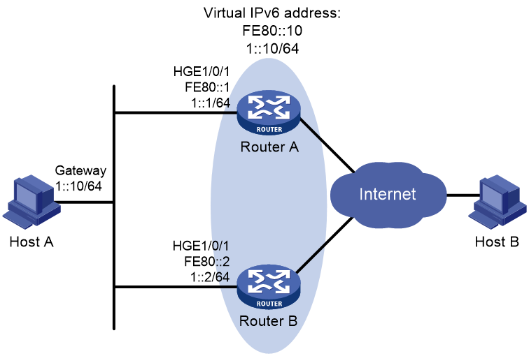
Prerequisites
By default, interfaces on the device are disabled (in ADM or Administratively Down state). To have an interface operate, you must use the undo shutdown command to enable that interface.
Procedure
1. Configure Router A:
# Specify an IPv6 address for Router A.
<RouterA> system-view
[RouterA] interface hundredgige 1/0/1
[RouterA-HundredGigE1/0/1] ipv6 address fe80::1 link-local
[RouterA-HundredGigE1/0/1] ipv6 address 1::1 64
# Create VRRP group 1, and set its virtual IPv6 addresses to FE80::10 and 1::10.
[RouterA-HundredGigE1/0/1] vrrp ipv6 vrid 1 virtual-ip fe80::10 link-local
[RouterA-HundredGigE1/0/1] vrrp ipv6 vrid 1 virtual-ip 1::10
# Assign Router A a higher priority than Router B in VRRP group 1, so Router A can become the master.
[RouterA-HundredGigE1/0/1] vrrp ipv6 vrid 1 priority 110
# Configure Router A to operate in preemptive mode, so it can become the master whenever it operates correctly. Set the preemption delay to 5000 centiseconds to avoid frequent status switchover.
[RouterA-HundredGigE1/0/1] vrrp ipv6 vrid 1 preempt-mode delay 5000
# Enable Router A to send RA messages, so Host A can learn the default gateway address.
[RouterA-HundredGigE1/0/1] undo ipv6 nd ra halt
2. Configure Router B:
# Specify an IPv6 address for Router B.
<RouterB> system-view
[RouterB] interface hundredgige 1/0/1
[RouterB-HundredGigE1/0/1] ipv6 address fe80::2 link-local
[RouterB-HundredGigE1/0/1] ipv6 address 1::2 64
# Create VRRP group 1, and set its virtual IPv6 addresses to FE80::10 and 1::10.
[RouterB-HundredGigE1/0/1] vrrp ipv6 vrid 1 virtual-ip fe80::10 link-local
[RouterB-HundredGigE1/0/1] vrrp ipv6 vrid 1 virtual-ip 1::10
# Configure Router B to operate in preemptive mode, and set the preemption delay to 5000 centiseconds.
[RouterB-HundredGigE1/0/1] vrrp ipv6 vrid 1 preempt-mode delay 5000
# Enable Router B to send RA messages, so Host A can learn the default gateway address.
[RouterB-HundredGigE1/0/1] undo ipv6 nd ra halt
Verifying the configuration
# Ping Host B from Host A. (Details not shown.)
# Display detailed information about VRRP group 1 on Router A.
[RouterA-HundredGigE1/0/1] display vrrp ipv6 verbose
IPv6 virtual router information:
Running mode : Standard
Total number of virtual routers : 1
Interface HundredGigE1/0/1
VRID : 1 Adver timer : 100 centiseconds
Admin status : Up State : Master
Config pri : 110 Running pri : 110
Preempt mode : Yes Delay time : 5000 centiseconds
Auth type : Not supported
Virtual IP : FE80::10
1::10
Virtual MAC : 0000-5e00-0201
Master IP : FE80::1
# Display detailed information about VRRP group 1 on Router B.
[RouterB-HundredGigE1/0/1] display vrrp ipv6 verbose
IPv6 virtual router information:
Running mode : Standard
Total number of virtual routers : 1
Interface HundredGigE1/0/1
VRID : 1 Adver timer : 100 centiseconds
Admin status : Up State : Backup
Config pri : 100 Running pri : 100
Preempt mode : Yes Delay time : 5000 centiseconds
Become master : 411 milliseconds left
Auth type : Not supported
Virtual IP : FE80::10
1::10
Master IP : FE80::1
The output shows that Router A is operating as the master in VRRP group 1 to forward packets from Host A to Host B.
# Disconnect the link between Host A and Router A, and verify that Host A can still ping Host B. (Details not shown.)
# Display detailed information about VRRP group 1 on Router B.
[RouterB-HundredGigE1/0/1] display vrrp ipv6 verbose
IPv6 virtual router information:
Running mode : Standard
Total number of virtual routers : 1
Interface HundredGigE1/0/1
VRID : 1 Adver timer : 100 centiseconds
Admin status : Up State : Master
Config pri : 100 Running pri : 100
Preempt mode : Yes Delay time : 5000 centiseconds
Auth type : Not supported
Virtual IP : FE80::10
1::10
Virtual MAC : 0000-5e00-0201
Master IP : FE80::2
The output shows that when Router A fails, Router B takes over to forward packets from Host A to Host B.
# Recover the link between Host A and Router A, and display detailed information about VRRP group 1 on Router A.
[RouterA-HundredGigE1/0/1] display vrrp ipv6 verbose
IPv6 virtual router information:
Running mode : Standard
Total number of virtual routers : 1
Interface HundredGigE1/0/1
VRID : 1 Adver timer : 100 centiseconds
Admin status : Up State : Master
Config pri : 110 Running pri : 110
Preempt mode : Yes Delay time : 5000 centiseconds
Auth type : Not supported
Virtual IP : FE80::10
1::10
Virtual MAC : 0000-5e00-0201
Master IP : FE80::1
The output shows that after Router A resumes normal operation, it becomes the master to forward packets from Host A to Host B.
Example: Configuring multiple VRRP groups
Network configuration
As shown in Figure 17, Router A and Router B form two VRRP groups to implement load sharing and mutual backup. VRRP group 1 uses the virtual IP address 1::10/64 to provide gateway service for some hosts on the subnet 1::/64. VRRP group 2 uses the virtual IP address 1::20/64 to provide gateway service for the other hosts on the subnet.
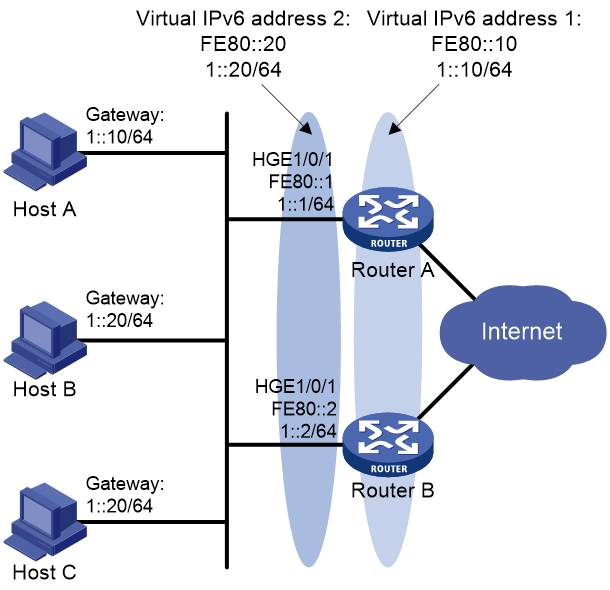
Prerequisites
By default, interfaces on the device are disabled (in ADM or Administratively Down state). To have an interface operate, you must use the undo shutdown command to enable that interface.
To implement load sharing between the VRRP groups, manually configure the default gateway 1::10 or 1::20 for the hosts on the subnet 1::/64.
Procedure
1. Configure Router A:
# Specify an IPv6 address for Router A.
<RouterA> system-view
[RouterA] interface hundredgige 1/0/1
[RouterA-HundredGigE1/0/1] ipv6 address fe80::1 link-local
[RouterA-HundredGigE1/0/1] ipv6 address 1::1 64
# Create VRRP group 1, and set its virtual IPv6 addresses to FE80::10 to 1::10.
[RouterA-HundredGigE1/0/1] vrrp ipv6 vrid 1 virtual-ip fe80::10 link-local
[RouterA-HundredGigE1/0/1] vrrp ipv6 vrid 1 virtual-ip 1::10
# Assign a higher priority to Router A than Router B in VRRP group 1, so Router A can become the master in the group.
[RouterA-HundredGigE1/0/1] vrrp ipv6 vrid 1 priority 110
# Create VRRP group 2, and set its virtual IPv6 addresses to FE80::20 and 1::20.
[RouterA-HundredGigE1/0/1] vrrp ipv6 vrid 2 virtual-ip fe80::20 link-local
[RouterA-HundredGigE1/0/1] vrrp ipv6 vrid 2 virtual-ip 1::20
2. Configure Router B:
# Specify an IPv6 address for Router B.
<RouterB> system-view
[RouterB] interface hundredgige 1/0/1
[RouterB-HundredGigE1/0/1] ipv6 address fe80::2 link-local
[RouterB-HundredGigE1/0/1] ipv6 address 1::2 64
# Create VRRP group 1, and set its virtual IPv6 addresses to FE80::10 and 1::10.
[RouterB-HundredGigE1/0/1] vrrp ipv6 vrid 1 virtual-ip fe80::10 link-local
[RouterB-HundredGigE1/0/1] vrrp ipv6 vrid 1 virtual-ip 1::10
# Create VRRP group 2, and set its virtual IPv6 addresses to FE80::20 and 1::20.
[RouterB-HundredGigE1/0/1] vrrp ipv6 vrid 2 virtual-ip fe80::20 link-local
[RouterB-HundredGigE1/0/1] vrrp ipv6 vrid 2 virtual-ip 1::20
# Assign Router B a higher priority than Router A in VRRP group 2, so Router B can become the master in the group.
[RouterB-HundredGigE1/0/1] vrrp ipv6 vrid 2 priority 110
Verifying the configuration
# Display detailed information about the VRRP groups on Router A.
[RouterA-HundredGigE1/0/1] display vrrp ipv6 verbose
IPv6 virtual router information:
Running mode : Standard
Total number of virtual routers : 2
Interface HundredGigE1/0/1
VRID : 1 Adver timer : 100 centiseconds
Admin status : Up State : Master
Config pri : 110 Running pri : 110
Preempt mode : Yes Delay time : 0 centiseconds
Auth type : Not supported
Virtual IP : FE80::10
1::10
Virtual MAC : 0000-5e00-0201
Master IP : FE80::1
Interface HundredGigE1/0/1
VRID : 2 Adver timer : 100 centiseconds
Admin status : Up State : Backup
Config pri : 100 Running pri : 100
Preempt mode : Yes Delay time : 0 centiseconds
Become master : 410 milliseconds left
Auth type : Not supported
Virtual IP : FE80::20
1::20
Master IP : FE80::2
# Display detailed information about the VRRP groups on Router B.
[RouterB-HundredGigE1/0/1] display vrrp ipv6 verbose
IPv6 virtual router information:
Running mode : Standard
Total number of virtual routers : 2
Interface HundredGigE1/0/1
VRID : 1 Adver timer : 100 centiseconds
Admin status : Up State : Backup
Config pri : 100 Running pri : 100
Preempt mode : Yes Delay time : 0 centiseconds
Become master : 407 milliseconds left
Auth type : Not supported
Virtual IP : FE80::10
1::10
Master IP : FE80::1
Interface HundredGigE1/0/1
VRID : 2 Adver timer : 100 centiseconds
Admin status : Up State : Master
Config pri : 110 Running pri : 110
Preempt mode : Yes Delay time : 0 centiseconds
Auth type : Not supported
Virtual IP : FE80::20
1::20
Virtual MAC : 0000-5e00-0202
Master IP : FE80::2
The output shows the following information:
· Router A is operating as the master in VRRP group 1 to forward Internet traffic for hosts that use the default gateway 1::10/64.
· Router B is operating as the master in VRRP group 2 to forward Internet traffic for hosts that use the default gateway 1::20/64.
Example: Configuring VRRP load balancing
Network configuration
As shown in Figure 18, Router A, Router B, and Router C form a load balanced VRRP group and use the virtual IPv6 addresses FE80::10 and 1::10 to provide gateway service for the subnet 1::/64.
Hosts on subnet 1::/64 learn 1::10 as their default gateway from RA messages sent by the routers.
Configure VFs on Router A, Router B, or Router C to monitor their respective HundredGigE 1/0/2. When the interface on any of them fails, the weights of the VFs on the problematic router decrease so another AVF can take over.
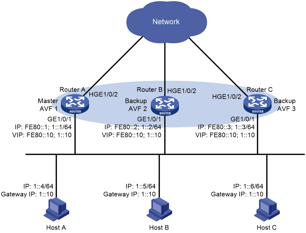
Prerequisites
By default, interfaces on the device are disabled (in ADM or Administratively Down state). To have an interface operate, you must use the undo shutdown command to enable that interface.
Procedure
1. Configure Router A:
# Configure VRRP to operate in load balancing mode.
<RouterA> system-view
[RouterA] vrrp ipv6 mode load-balance
# Create VRRP group 1, and set its virtual IPv6 addresses to FE80::10 and 1::10.
[RouterA] interface hundredgige 1/0/1
[RouterA-HundredGigE1/0/1] ipv6 address fe80::1 link-local
[RouterA-HundredGigE1/0/1] ipv6 address 1::1 64
[RouterA-HundredGigE1/0/1] vrrp ipv6 vrid 1 virtual-ip fe80::10 link-local
[RouterA-HundredGigE1/0/1] vrrp ipv6 vrid 1 virtual-ip 1::10
# Assign Router A the highest priority in VRRP group 1, so Router A can become the master.
[RouterA-HundredGigE1/0/1] vrrp ipv6 vrid 1 priority 120
# Configure Router A to operate in preemptive mode, so it can become the master whenever it operates correctly. Set the preemption delay to 5000 centiseconds to avoid frequent status switchover.
[RouterA-HundredGigE1/0/1] vrrp ipv6 vrid 1 preempt-mode delay 5000
# Enable Router A to send RA messages, so hosts on subnet 1::/64 can learn the default gateway address.
[RouterA-HundredGigE1/0/1] undo ipv6 nd ra halt
[RouterA-HundredGigE1/0/1] quit
# Create track entry 1 to monitor the upstream link status of HundredGigE 1/0/2. When the upstream link fails, the track entry transits to Negative.
[RouterA] track 1 interface hundredgige 1/0/2
# Associate the VFs in VRRP group 1 with track entry 1, and decrease their weights by 250 when the track entry transits to Negative.
[RouterA] interface hundredgige 1/0/1
[RouterA-HundredGigE1/0/1] vrrp ipv6 vrid 1 track 1 weight reduced 250
2. Configure Router B:
# Configure VRRP to operate in load balancing mode.
<RouterB> system-view
[RouterB] vrrp ipv6 mode load-balance
# Create VRRP group 1, and set its virtual IPv6 addresses to FE80::10 and 1::10.
[RouterB] interface hundredgige 1/0/1
[RouterB-HundredGigE1/0/1] ipv6 address fe80::2 link-local
[RouterB-HundredGigE1/0/1] ipv6 address 1::2 64
[RouterB-HundredGigE1/0/1] vrrp ipv6 vrid 1 virtual-ip fe80::10 link-local
[RouterB-HundredGigE1/0/1] vrrp ipv6 vrid 1 virtual-ip 1::10
# Assign Router B a higher priority than Router C in VRRP group 1, so Router B can become the master when Router A fails.
[RouterB-HundredGigE1/0/1] vrrp ipv6 vrid 1 priority 110
# Configure Router B to operate in preemptive mode and set the preemption delay to 5000 centiseconds.
[RouterB-HundredGigE1/0/1] vrrp ipv6 vrid 1 preempt-mode delay 5000
# Enable Router B to send RA messages, so hosts on subnet 1::/64 can learn the default gateway address.
[RouterB-HundredGigE1/0/1] undo ipv6 nd ra halt
[RouterB-HundredGigE1/0/1] quit
# Create track entry 1 to monitor the upstream link status of HundredGigE 1/0/2. When the upstream link fails, the track entry transits to Negative.
[RouterB] track 1 interface hundredgige 1/0/2
# Associate the VFs in VRRP group 1 with track entry 1, and decrease their weights by 250 when the track entry transits to Negative.
[RouterB] interface hundredgige 1/0/1
[RouterB-HundredGigE1/0/1] vrrp ipv6 vrid 1 track 1 weight reduced 250
3. Configure Router C:
# Configure VRRP to operate in load balancing mode.
<RouterC> system-view
[RouterC] vrrp ipv6 mode load-balance
# Create VRRP group 1 and set its virtual IPv6 addresses to FE80::10 and 1::10.
[RouterC] interface hundredgige 1/0/1
[RouterC-HundredGigE1/0/1] ipv6 address fe80::3 link-local
[RouterC-HundredGigE1/0/1] ipv6 address 1::3 64
[RouterC-HundredGigE1/0/1] vrrp ipv6 vrid 1 virtual-ip fe80::10 link-local
[RouterC-HundredGigE1/0/1] vrrp ipv6 vrid 1 virtual-ip 1::10
# Configure Router C to operate in preemptive mode and set the preemption delay to 5000 centiseconds.
[RouterC-HundredGigE1/0/1] vrrp ipv6 vrid 1 preempt-mode delay 5000
# Enable Router C to send RA messages, so hosts on subnet 1::/64 can learn the default gateway address.
[RouterC-HundredGigE1/0/1] undo ipv6 nd ra halt
[RouterC-HundredGigE1/0/1] quit
# Create track entry 1 to monitor the upstream link status of HundredGigE 1/0/2. When the upstream link fails, the track entry transits to Negative.
[RouterC] track 1 interface hundredgige 1/0/2
# Associate the VFs in VRRP group 1 with track entry 1, and decrease their weights by 250 when the track entry transits to Negative.
[RouterC] interface hundredgige 1/0/1
[RouterC-HundredGigE1/0/1] vrrp ipv6 vrid 1 track 1 weight reduced 250
Verifying the configuration
# Verify that Host A can ping the external network. (Details not shown.)
# Display detailed information about VRRP group 1 on Router A.
[RouterA-HundredGigE1/0/1] display vrrp ipv6 verbose
IPv6 virtual router information:
Running mode : Load balance
Total number of virtual routers : 1
Interface HundredGigE1/0/1
VRID : 1 Adver timer : 100 centiseconds
Admin status : Up State : Master
Config pri : 120 Running pri : 120
Preempt mode : Yes Delay time : 5000 centiseconds
Auth type : Not supported
Virtual IP : FE80::10
1::10
Member IP list : FE80::1 (Local, Master)
FE80::2 (Backup)
FE80::3 (Backup)
Forwarder information: 3 Forwarders 1 Active
Config weight : 255
Running weight : 255
Forwarder 01
State : Active
Virtual MAC : 000f-e2ff-4011 (Owner)
Owner ID : 0000-5e01-1101
Priority : 255
Active : local
Forwarder 02
State : Listening
Virtual MAC : 000f-e2ff-4012 (Learnt)
Owner ID : 0000-5e01-1103
Priority : 127
Active : FE80::2
Forwarder 03
State : Listening
Virtual MAC : 000f-e2ff-4013 (Learnt)
Owner ID : 0000-5e01-1105
Priority : 127
Active : FE80::3
Forwarder weight track information:
Track object : 1 State : Positive Weight reduced : 250
# Display detailed information about VRRP group 1 on Router B.
[RouterB-HundredGigE1/0/1] display vrrp ipv6 verbose
IPv6 virtual router information:
Running mode : Load balance
Total number of virtual routers : 1
Interface HundredGigE1/0/1
VRID : 1 Adver timer : 100 centiseconds
Admin status : Up State : Backup
Config pri : 110 Running pri : 110
Preempt mode : Yes Delay time : 5000 centiseconds
Become master : 400 milliseconds left
Auth type : Not supported
Virtual IP : FE80::10
1::10
Member IP list : FE80::2 (Local, Backup)
FE80::1 (Master)
FE80::3 (Backup)
Forwarder information: 3 Forwarders 1 Active
Config weight : 255
Running weight : 255
Forwarder 01
State : Listening
Virtual MAC : 000f-e2ff-4011 (Learnt)
Owner ID : 0000-5e01-1101
Priority : 127
Active : FE80::1
Forwarder 02
State : Active
Virtual MAC : 000f-e2ff-4012 (Owner)
Owner ID : 0000-5e01-1103
Priority : 255
Active : local
Forwarder 03
State : Listening
Virtual MAC : 000f-e2ff-4013 (Learnt)
Owner ID : 0000-5e01-1105
Priority : 127
Active : FE80::3
Forwarder weight track information:
Track object : 1 State : Positive Weight reduced : 250
# Display detailed information about VRRP group 1 on Router C.
[RouterC-HundredGigE1/0/1] display vrrp ipv6 verbose
IPv6 virtual router information:
Running mode : Load balance
Total number of virtual routers : 1
Interface HundredGigE1/0/1
VRID : 1 Adver timer : 100 centiseconds
Admin status : Up State : Backup
Config pri : 100 Running pri : 100
Preempt mode : Yes Delay time : 5000 centiseconds
Become master : 402 milliseconds left
Auth type : Not supported
Virtual IP : FE80::10
1::10
Member IP list : FE80::3 (Local, Backup)
FE80::1 (Master)
FE80::2 (Backup)
Forwarder information: 3 Forwarders 1 Active
Config weight : 255
Running weight : 255
Forwarder 01
State : Listening
Virtual MAC : 000f-e2ff-4011 (Learnt)
Owner ID : 0000-5e01-1101
Priority : 127
Active : FE80::1
Forwarder 02
State : Listening
Virtual MAC : 000f-e2ff-4012 (Learnt)
Owner ID : 0000-5e01-1103
Priority : 127
Active : FE80::2
Forwarder 03
State : Active
Virtual MAC : 000f-e2ff-4013 (Owner)
Owner ID : 0000-5e01-1105
Priority : 255
Active : local
Forwarder weight track information:
Track object : 1 State : Positive Weight reduced : 250
The output shows that Router A is the master in VRRP group 1, and each of the three routers has one AVF and two LVFs.
# Disconnect the link of HundredGigE 1/0/2 on Router A, and display detailed information about VRRP group 1 on Router A.
[RouterA-HundredGigE1/0/1] display vrrp ipv6 verbose
IPv6 virtual router information:
Running mode : Load balance
Total number of virtual routers : 1
Interface HundredGigE1/0/1
VRID : 1 Adver timer : 100 centiseconds
Admin status : Up State : Master
Config pri : 120 Running pri : 120
Preempt mode : Yes Delay Time : 5000 centiseconds
Auth type : Not supported
Virtual IP : FE80::10
1::10
Member IP list : FE80::1 (Local, Master)
FE80::2 (Backup)
FE80::3 (Backup)
Forwarder information: 3 Forwarders 0 Active
Config weight : 255
Running weight : 5
Forwarder 01
State : Initialize
Virtual MAC : 000f-e2ff-4011 (Owner)
Owner ID : 0000-5e01-1101
Priority : 0
Active : FE80::3
Forwarder 02
State : Initialize
Virtual MAC : 000f-e2ff-4012 (Learnt)
Owner ID : 0000-5e01-1103
Priority : 0
Active : FE80::2
Forwarder 03
State : Initialize
Virtual MAC : 000f-e2ff-4013 (Learnt)
Owner ID : 0000-5e01-1105
Priority : 0
Active : FE80::3
Forwarder weight track information:
Track object : 1 State : Negative Weight reduced : 250
# Display detailed information about VRRP group 1 on Router C.
[RouterC-HundredGigE1/0/1] display vrrp ipv6 verbose
IPv6 virtual router information:
Running mode : Load balance
Total number of virtual routers : 1
Interface HundredGigE1/0/1
VRID : 1 Adver timer : 100 centiseconds
Admin status : Up State : Backup
Config pri : 100 Running pri : 100
Preempt mode : Yes Delay time : 5000 centiseconds
Become master : 401 milliseconds left
Auth type : Not supported
Virtual IP : FE80::10
1::10
Member IP list : FE80::3 (Local, Backup)
FE80::1 (Master)
FE80::2 (Backup)
Forwarder information: 3 Forwarders 2 Active
Config weight : 255
Running weight : 255
Forwarder 01
State : Active
Virtual MAC : 000f-e2ff-4011 (Take Over)
Owner ID : 0000-5e01-1101
Priority : 85
Active : local
Forwarder 02
State : Listening
Virtual MAC : 000f-e2ff-4012 (Learnt)
Owner ID : 0000-5e01-1103
Priority : 85
Active : FE80::2
Forwarder 03
State : Active
Virtual MAC : 000f-e2ff-4013 (Owner)
Owner ID : 0000-5e01-1105
Priority : 255
Active : local
Forwarder weight track information:
Track object : 1 State : Positive Weight reduced : 250
The output shows that when HundredGigE 1/0/2 on Router A fails, the weights of the VFs on Router A drop below the lower limit of failure. All VFs on Router A transit to the Initialize state and cannot forward traffic. The VF for MAC address 000f-e2ff-4011 on Router C becomes the AVF to forward traffic.
# When the timeout timer (about 1800 seconds) expires, display detailed information about VRRP group 1 on Router C.
[RouterC-HundredGigE1/0/1] display vrrp ipv6 verbose
IPv6 virtual router information:
Running mode : Load balance
Total number of virtual routers : 1
Interface HundredGigE1/0/1
VRID : 1 Adver timer : 100 centiseconds
Admin status : Up State : Backup
Config pri : 100 Running pri : 100
Preempt mode : Yes Delay time : 5000 centiseconds
Become master : 400 milliseconds left
Auth type : Not supported
Virtual IP : FE80::10
1::10
Member IP list : FE80::3 (Local, Backup)
FE80::1 (Master)
FE80::2 (Backup)
Forwarder information: 2 Forwarders 1 Active
Config weight : 255
Running weight : 255
Forwarder 02
State : Listening
Virtual MAC : 000f-e2ff-4012 (Learnt)
Owner ID : 0000-5e01-1103
Priority : 127
Active : FE80::2
Forwarder 03
State : Active
Virtual MAC : 000f-e2ff-4013 (Owner)
Owner ID : 0000-5e01-1105
Priority : 255
Active : local
Forwarder weight track information:
Track object : 1 State : Positive Weight reduced : 250
The output shows that when the timeout timer expires, the VF for virtual MAC address 000f-e2ff-4011 is removed. The VF no longer forwards the packets destined for the MAC address.
# When Router A fails, display detailed information about VRRP group 1 on Router B.
[RouterB-HundredGigE1/0/1] display vrrp ipv6 verbose
IPv6 virtual router information:
Running mode : Load balance
Total number of virtual routers : 1
Interface HundredGigE1/0/1
VRID : 1 Adver timer : 100 centiseconds
Admin status : Up State : Master
Config pri : 110 Running pri : 110
Preempt mode : Yes Delay time : 5000 centiseconds
Auth type : Not supported
Virtual IP : FE80::10
1::10
Member IP list : FE80::2 (Local, Master)
FE80::3 (Backup)
Forwarder information: 2 Forwarders 1 Active
Config weight : 255
Running weight : 255
Forwarder 02
State : Active
Virtual MAC : 000f-e2ff-4012 (Owner)
Owner ID : 0000-5e01-1103
Priority : 255
Active : local
Forwarder 03
State : Listening
Virtual MAC : 000f-e2ff-4013 (Learnt)
Owner ID : 0000-5e01-1105
Priority : 127
Active : FE80::3
Forwarder weight track information:
Track object : 1 State : Positive Weight reduced : 250
The output shows the following information:
· When Router A fails, Router B becomes the master because it has a higher priority than Router C.
· The VF for virtual MAC address 000f-e2ff-4011 is removed.
Troubleshooting VRRP
An error prompt is displayed
Symptom
An error prompt "The virtual router detected a VRRP configuration error." is displayed during configuration.
Analysis
This symptom is probably caused by the following reasons:
· The VRRP advertisement interval in the packet is not the same as that for the current VRRP group (in VRRPv2 only).
· The number of virtual IP addresses in the packet is not the same as that for the current VRRP group.
· The virtual IP address list is not the same as that for the current VRRP group.
· A device in the VRRP group receives illegitimate VRRP packets. For example, the IP address owner receives a VRRP packet with the priority 255.
Solution
To resolve the problem:
1. Modify the configuration on routers in VRRP groups to ensure consistent configuration.
2. Take fault location and anti-attack measures to eliminate potential threats.
3. If the problem persists, contact H3C Support.
Multiple masters appear in a VRRP group
Symptom
Multiple masters appear in a VRRP group.
Analysis
It is normal for a VRRP group to have multiple masters for a short time, and this situation requires no manual intervention.
If multiple masters coexist for a longer period, check for the following conditions:
· The masters cannot receive advertisements from each other.
· The received advertisements are illegitimate.
Solution
To resolve the problem:
1. Ping between these masters:
¡ If the ping operation fails, examine network connectivity.
¡ If the ping operation succeeds, check for configuration inconsistencies in the number of virtual IP addresses, virtual IP addresses, and authentication. For IPv4 VRRP, also make sure the same version of VRRP is configured on all routers in the VRRP group. For VRRPv2, make sure the same VRRP advertisement interval is configured on the routers in the VRRP group.
2. If the problem persists, contact H3C Support.
Fast VRRP state flapping
Symptom
Fast VRRP state flapping occurs.
Analysis
The VRRP advertisement interval is set too short.
Solution
To resolve the problem:
1. Increase the interval for sending VRRP advertisements or introduce a preemption delay.
2. If the problem persists, contact H3C Support.
