- Table of Contents
-
- 01-Typical configuration example
- 01-AAA_Configuration_Examples
- 02-ACL_Configuration_Examples
- 03-ATM_Configuration_Examples
- 04-IGMP_Configuration_Examples
- 05-IP_Source_Guard_Configuration_Examples
- 06-Ethernet_OAM_Configuration_Examples
- 07-NQA_Configuration_Examples
- 08-QinQ_Configuration_Examples
- 09-OSPF_Configuration_Examples
- 10-MPLS_TE_Configuration_Examples
- 11-OpenFlow_Configuration_Examples
- 12-NAT_Configuration_Examples
- 13-RBAC_Configuration_Examples
- 14-IRF_Configuration_Examples
- 15-POS_Interface_Configuration_Examples
- 16-CPOS_Interface_Configuration_Examples
- 17-DLDP_Configuration_Examples
- 18-IS-IS_Configuration_Examples
- 19-MPLS_L3VPN_Configuration_Examples
- 20-SSH_Configuration_Examples
- 21-Login_Management_Configuration_Examples
- 22-SNMP_Configuration_Examples
- 23-Priority_Marking_and_Queue_Scheduling_Configuration_Examples
- 24-Multicast_VPN_Configuration_Examples
- 25-BGP_Configuration_Examples
- 26-HoVPN_Configuration_Examples
- 27-L2TP_Configuration_Examples
- 28-VRRP_Configuration_Examples
- 29-Traffic_Filtering_Configuration_Examples
- 30-Samplers_and_IPv4_NetStream_Configuration_Examples
- 31-Software_Upgrade_Examples
- 32-MPLS_L2VPN_Configuration_Examples
- 33-NetStream_Configuration_Examples
- 34-Policy-Based_Routing_Configuration_Examples
- 35-Traffic_Policing_Configuration_Examples
- 36-BFD_Configuration_Examples
- 37-OSPFv3_Configuration_Examples
- 38-VPLS_Configuration_Examples
- 39-GTS_and_Rate_Limiting_Configuration_Examples
- 40-IPv6_IS-IS_Configuration_Examples
- 41-MPLS OAM_Configuration_Examples
- 42-BGP_Route_Selection_Configuration_Examples
- 43-IS-IS_Route_Summarization_Configuration_Examples
- 44-Attack_Protection_Configuration_Examples
- Related Documents
-
| Title | Size | Download |
|---|---|---|
| 32-MPLS_L2VPN_Configuration_Examples | 228.52 KB |
Contents
Introduction
This document provides MPLS L2VPN configuration examples.
MPLS L2VPN is an MPLS-based Layer 2 VPN technology. It can transparently transmit Layer 2 data for different data link layer protocols over an MPLS network.
MPLS L2VPN can be implemented through the following PWs:
· LDP PWs.
· BGP PWs.
Prerequisites
The configuration examples in this document were created and verified in a lab environment, and all the devices were started with the factory default configuration. When you are working on a live network, make sure you understand the potential impact of every command on your network.
This document assumes that you have basic knowledge of MPLS L2VPN.
Example: Configuring LDP PWs
Network configuration
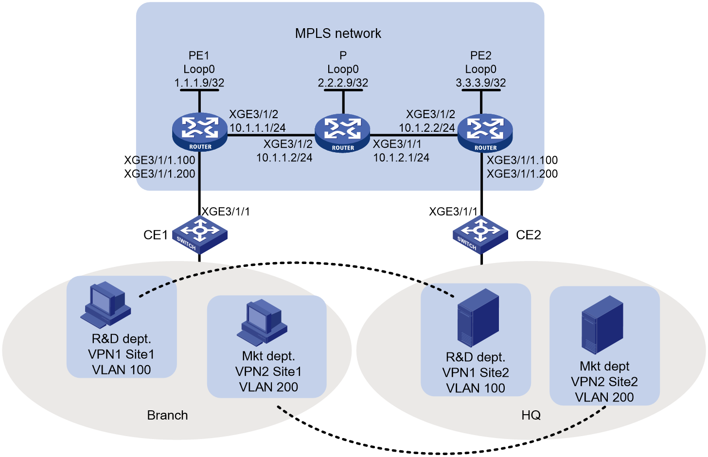
As shown in Figure 1, the MPLS network provides L2VPN services for a customer. Configure LDP PWs between PE 1 and PE 2 so the R&D and Marketing departments use different VPN connections to achieve data isolation.
Analysis
To use LDP PWs to implement MPLS L2VPN, configure two levels of labels:
· Inner labels—PW labels dynamically generated by LDP.
· Outer labels—Public tunnel labels dynamically generated by LDP in this example.
To identify packets to be transported by MPLS L2VPN, configure subinterfaces on the CE-facing ports of PEs.
Procedures
1. Configure OSPF on the MPLS backbone to ensure IP connectivity within the backbone:
# On PE 1, configure an IP address for Loopback 0.
<PE1> system-view
[PE1] interface loopback 0
[PE1-LoopBack0] ip address 1.1.1.9 32
[PE1-LoopBack0] quit
# On PE 1, configure an IP address for Ten-GigabitEthernet 3/1/2.
[PE1] interface Ten-GigabitEthernet 3/1/2
[PE1-Ten-GigabitEthernet3/1/2] ip address 10.1.1.1 24
[PE1-Ten-GigabitEthernet3/1/2] quit
# On PE 1, configure OSPF.
[PE1] ospf
[PE1-ospf-1] area 0
[PE1-ospf-1-area-0.0.0.0] network 10.1.1.0 0.0.0.255
[PE1-ospf-1-area-0.0.0.0] network 1.1.1.9 0.0.0.0
[PE1-ospf-1-area-0.0.0.0] quit
[PE1-ospf-1] quit
# On P, configure an IP address for Loopback 0.
<P> system-view
[P] interface loopback 0
[P-LoopBack0] ip address 2.2.2.9 32
[P-LoopBack0] quit
# On P, configure an IP address for Ten-GigabitEthernet 3/1/1.
[P] interface Ten-GigabitEthernet3/1/1
[P-Ten-GigabitEthernet3/1/1] ip address 10.1.2.1 24
[P-Ten-GigabitEthernet3/1/1] quit
# On P, configure an IP address for Ten-GigabitEthernet 3/1/2.
[P] interface Ten-GigabitEthernet3/1/2
[P-Ten-GigabitEthernet3/1/2] ip address 10.1.1.2 24
[P-Ten-GigabitEthernet3/1/2] quit
# On P, configure OSPF.
[P] ospf
[P-ospf-1] area 0
[P-ospf-1-area-0.0.0.0] network 10.1.1.0 0.0.0.255
[P-ospf-1-area-0.0.0.0] network 10.1.2.0 0.0.0.255
[P-ospf-1-area-0.0.0.0] network 2.2.2.9 0.0.0.0
[P-ospf-1-area-0.0.0.0] quit
[P-ospf-1] quit
# On PE 2, configure an IP address for Loopback 0.
<PE2> system-view
[PE2] interface loopback 0
[PE2-LoopBack0] ip address 3.3.3.9 32
[PE2-LoopBack0] quit
# On PE 2, configure an IP address for Ten-GigabitEthernet 3/1/2.
[PE2] interface Ten-GigabitEthernet 3/1/2
[PE2-Ten-GigabitEthernet3/1/2] ip address 10.1.2.2 24
[PE2-Ten-GigabitEthernet3/1/2] quit
# On PE 2, configure OSPF.
[PE2] ospf
[PE2-ospf-1] area 0
[PE2-ospf-1-area-0.0.0.0] network 10.1.2.0 0.0.0.255
[PE2-ospf-1-area-0.0.0.0] network 3.3.3.9 0.0.0.0
[PE2-ospf-1-area-0.0.0.0] quit
[PE2-ospf-1] quit
2. Configure basic MPLS and MPLS LDP on the MPLS backbone to establish LDP LSPs:
# On PE 1, configure an LSR ID.
[PE1] mpls lsr-id 1.1.1.9
# On PE 1, enable LDP globally.
[PE1] mpls ldp
[PE1-ldp] quit
# On PE 1, enable MPLS and LDP on Ten-GigabitEthernet 3/1/2.
[PE1] interface Ten-GigabitEthernet 3/1/2
[PE1-Ten-GigabitEthernet 3/1/2] mpls enable
[PE1-Ten-GigabitEthernet 3/1/2] mpls ldp enable
[PE1-Ten-GigabitEthernet 3/1/2] quit
# On P, configure an LSR ID.
[P] mpls lsr-id 2.2.2.9
# On P, enable LDP globally.
[P] mpls ldp
[P-ldp] quit
# On P, enable MPLS and LDP on Ten-GigabitEthernet 3/1/1.
[P] interface Ten-GigabitEthernet3/1/1
[P-Ten-GigabitEthernet3/1/1] mpls enable
[P-Ten-GigabitEthernet3/1/1] quit
# On P, enable MPLS and LDP on Ten-GigabitEthernet 3/1/2.
[P] interface Ten-GigabitEthernet3/1/2
[P-Ten-GigabitEthernet3/1/2] mpls enable
[P-Ten-GigabitEthernet3/1/2] quit
# On PE 2, configure an LSR ID.
[PE2] mpls lsr-id 3.3.3.9
# On PE 2, enable LDP globally.
[PE2] mpls ldp
[PE2-ldp] quit
# On PE 2, enable MPLS and LDP on Ten-GigabitEthernet 3/1/2.
[PE2] interface Ten-GigabitEthernet 3/1/2
[PE2-Ten-GigabitEthernet3/1/2] mpls enable
[PE2-Ten-GigabitEthernet3/1/2] mpls ldp enable
[PE2-Ten-GigabitEthernet3/1/2] quit
3. Configure a subinterface for each department and bind the subinterfaces to their respective VPN connections:
# On PE 1, enable MPLS L2VPN globally.
[PE1] l2vpn enable
# On PE 1, create subinterfaces Ten-GigabitEthernet 3/1/1.100 and Ten-GigabitEthernet 3/1/1.200.
[PE1] interface Ten-GigabitEthernet 3/1/1.100
[PE1-Ten-GigabitEthernet3/1/1.100] vlan-type dot1q vid 100
[PE1-Ten-GigabitEthernet3/1/1.100] quit
[PE1] interface Ten-GigabitEthernet 3/1/1.200
[PE1-Ten-GigabitEthernet3/1/1.200] vlan-type dot1q vid 200
[PE1-Ten-GigabitEthernet3/1/1.200] quit
# On PE 1, create cross-connect group vpna, create cross-connect ldp in the group, and bind Ten-GigabitEthernet3/1/1.100 to the cross-connect.
[PE1] xconnect-group vpna
[PE1-xcg-vpna] connection ldp
[PE1-xcg-vpna-ldp] ac interface Ten-GigabitEthernet 3/1/1.100
[PE1-xcg-vpna-ldp-Ten-GigabitEthernet3/1/1.100] quit
[PE1-xcg-vpna-ldp] peer 3.3.3.9 pw-id 100
[PE1-xcg-vpna-ldp-3.3.3.9-100] quit
[PE1-xcg-vpna-ldp] quit
[PE1-xcg-vpna] quit
# On PE 1, create cross-connect group vpnb, create cross-connect ldp in the group, and bind Ten-GigabitEthernet 3/1/1.200 to the cross-connect.
[PE1] xconnect-group vpnb
[PE1-xcg-vpnb] connection ldp
[PE1-xcg-vpnb-ldp] ac interface Ten-GigabitEthernet 3/1/1.200
[PE1-xcg-vpnb-ldp] peer 3.3.3.9 pw-id 200
[PE1-xcg-vpnb-ldp-3.3.3.9-200] quit
[PE1-xcg-vpnb-ldp] quit
[PE1-xcg-vpnb] quit
# On PE 2, enable MPLS L2VPN globally.
[PE2] l2vpn enable
# On PE 2, create subinterfaces Ten-GigabitEthernet 3/1/1.100 and Ten-GigabitEthernet 3/1/1.200.
[PE2] interface Ten-GigabitEthernet 3/1/1.100
[PE2-Ten-GigabitEthernet3/1/1.100] vlan-type dot1q vid 100
[PE2-Ten-GigabitEthernet3/1/1.100] quit
[PE2] interface Ten-GigabitEthernet 3/1/1.200
[PE2-Ten-GigabitEthernet3/1/1.200] vlan-type dot1q vid 200
[PE2-Ten-GigabitEthernet3/1/1.200] quit
# On PE 2, create cross-connect group vpna, create cross-connect ldp in the group, and bind Ten-GigabitEthernet 3/1/1.100 to the cross-connect.
[PE2] xconnect-group vpna
[PE2-xcg-vpna] connection ldp
[PE2-xcg-vpna-ldp] ac interface Ten-GigabitEthernet 3/1/1.100
[PE2-xcg-vpna-ldp-Ten-GigabitEthernet3/1/1.100] quit
# On PE 2, create an LDP PW for the cross-connect to bind the AC to the PW.
[PE2-xcg-vpna-ldp] peer 1.1.1.9 pw-id 100
[PE2-xcg-vpna-ldp-1.1.1.9-100] quit
[PE2-xcg-vpna-ldp] quit
[PE2-xcg-vpna] quit
# On PE 2, create cross-connect group vpnb, create cross-connect ldp in the group, and bind Ten-GigabitEthernet 3/1/1.200 to the cross-connect.
[PE2] xconnect-group vpnb
[PE2-xcg-vpnb] connection ldp
[PE2-xcg-vpnb-ldp] ac interface Ten-GigabitEthernet 3/1/1.200
[PE2-xcg-vpna-ldp-Ten-GigabitEthernet3/1/1.200] quit
# On PE 2, create an LDP PW for the cross-connect to bind the AC to the PW.
[PE2-xcg-vpnb-ldp] peer 1.1.1.9 pw-id 200
[PE2-xcg-vpnb-ldp-1.1.1.9-200] quit
[PE2-xcg-vpnb-ldp] quit
[PE2-xcg-vpnb] quit
4. Allow CE access to PEs:
# On CE 1, configure the interface connected to the PE to permit tagged packets from the customer VLANs.
<CE1> system-view
[CE1] vlan 100
[CE1-vlan100] quit
[CE1] vlan 200
[CE1-vlan200] quit
[CE1] interface Ten-GigabitEthernet 3/1/1
[CE1-Ten-GigabitEthernet3/1/1] port link-type trunk
[CE1-Ten-GigabitEthernet3/1/1] port trunk permit vlan 100 200
# Configure other CEs in the same way that CE 1 is configured. (Details not shown.)
Verifying the configuration
# Display L2VPN PW information on PE 1. The output shows that two LDP PWs have been established.
[PE1] display l2vpn pw
Flags: M - main, B - backup, E - ecmp, BY - bypass, H - hub link, S - spoke link
N - no split horizon, A - administration, ABY – ac-bypass
PBY – pw-bypass
Total number of PWs: 2
2 up, 0 blocked, 0 down, 0 defect, 0 idle, 0 duplicate
Xconnect-group Name: vpna
Peer PWID/RmtSite/SrvID In/Out Label Proto Flag Link ID State
3.3.3.9 100 65663/65663 LDP M 1 Up
Xconnect-group Name: vpnb
Peer PWID/RmtSite/SrvID In/Out Label Proto Flag Link ID State
3.3.3.9 200 65662/65662 LDP M 1 Up
# Display L2VPN PW information on PE 2. The output shows that two LDP PWs have been established.
[PE2] display l2vpn pw
Flags: M - main, B - backup, E - ecmp, BY - bypass, H - hub link, S - spoke link
N - no split horizon, A - administration, ABY – ac-bypass
PBY – pw-bypass
Total number of PWs: 2
2 up, 0 blocked, 0 down, 0 defect, 0 idle, 0 duplicate
Xconnect-group Name: vpna
Peer PWID/RmtSite/SrvID In/Out Label Proto Flag Link ID State
1.1.1.9 100 65663/65663 LDP M 1 Up
Xconnect-group Name: vpnb
Peer PWID/RmtSite/SrvID In/Out Label Proto Flag Link ID State
1.1.1.9 200 65662/65662 LDP M 1 Up
# Verify that the host and the server in the same VLAN can ping each other. (Details not shown.)
Configuration files
· CE 1 and CE 2:
#
vlan 100
#
vlan 200
#
interface Ten-GigabitEthernet3/1/1
port link-mode bridge
port link-type trunk
port trunk permit vlan 1 100 200
#
· PE 1:
#
ospf 1
area 0.0.0.0
network 1.1.1.9 0.0.0.0
network 10.1.1.0 0.0.0.255
#
mpls lsr-id 1.1.1.9
#
mpls ldp
#
l2vpn enable
#
interface LoopBack0
ip address 1.1.1.9 255.255.255.255
#
interface Ten-GigabitEthernet3/1/1
port link-mode route
#
interface Ten-GigabitEthernet3/1/1.100
vlan-type dot1q vid 100
#
interface Ten-GigabitEthernet3/1/1.200
vlan-type dot1q vid 200
#
interface Ten-GigabitEthernet3/1/2
port link-mode route
ip address 10.1.1.1 255.255.255.0
mpls enable
mpls ldp enable
#
xconnect-group vpna
connection ldp
ac interface Ten-GigabitEthernet3/1/1.100
peer 3.3.3.9 pw-id 100
#
xconnect-group vpnb
connection ldp
ac interface Ten-GigabitEthernet3/1/1.200
peer 3.3.3.9 pw-id 200
#
· P:
#
ospf 1
area 0.0.0.0
network 10.1.1.0 0.0.0.255
network 10.1.2.0 0.0.0.255
network 2.2.2.9 0.0.0.0
#
mpls lsr-id 2.2.2.9
#
mpls ldp
#
interface LoopBack0
ip address 2.2.2.9 255.255.255.255
#
interface Ten-GigabitEthernet3/1/1
port link-mode route
ip address 10.1.2.1 255.255.255.0
mpls enable
mpls ldp enable
#
interface Ten-GigabitEthernet3/1/2
port link-mode route
ip address 10.1.1.2 255.255.255.0
mpls enable
mpls ldp enable
#
· PE 2:
#
ospf 1
area 0.0.0.0
network 10.1.2.0 0.0.0.255
network 3.3.3.9 0.0.0.0
#
mpls lsr-id 3.3.3.9
#
mpls ldp
#
l2vpn enable
#
interface LoopBack0
ip address 3.3.3.9 255.255.255.255
#
interface Ten-GigabitEthernet3/1/1
port link-mode route
#
interface Ten-GigabitEthernet3/1/1.100
vlan-type dot1q vid 100
#
interface Ten-GigabitEthernet3/1/1.200
vlan-type dot1q vid 200
#
interface Ten-GigabitEthernet3/1/2
port link-mode route
ip address 10.1.2.2 255.255.255.0
mpls enable
mpls ldp enable
#
xconnect-group vpna
connection ldp
ac interface Ten-GigabitEthernet3/1/1.100
peer 1.1.1.9 pw-id 100
#
xconnect-group vpnb
connection ldp
ac interface Ten-GigabitEthernet3/1/1.200
peer 1.1.1.9 pw-id 200
#
Example: Configuring a BGP PW
Network configuration
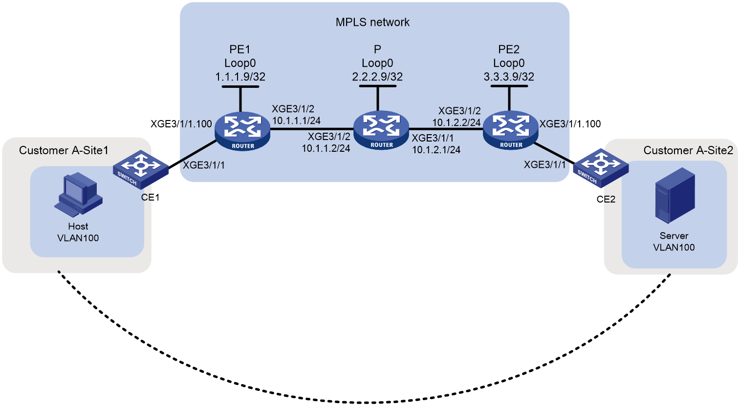
As shown in Figure 2, a customer has two VPN sites and will add eight sites in the future. Configure a BGP PW between PE 1 and PE 2 to allow VPN communication between the two sites and reserve enough VPN resources for future extension.
Analysis
To use BGP PWs to implement MPLS L2VPN, configure two levels of labels:
· Inner labels—PW labels dynamically generated by BGP.
· Outer labels—Public tunnel labels dynamically generated by LDP in this example.
To use BGP to transmit inner labels between PEs, create a subinterface and an IBGP connection, and specify the peer PE as a BGP peer on each PE.
To simplify configuration required by future expansion of the customer network, set the maximum number of CEs in the VPN to 10.
Procedures
1. Configure OSPF on the MPLS backbone to ensure IP connectivity within the backbone:
# On PE 1, configure an IP address for Loopback 0.
<PE1> system-view
[PE1] interface loopback 0
[PE1-LoopBack0] ip address 1.1.1.9 32
[PE1-LoopBack0] quit
# On PE 1, configure an IP address for Ten-GigabitEthernet 3/1/2.
[PE1] interface Ten-GigabitEthernet 3/1/2
[PE1-Ten-GigabitEthernet 3/1/2] ip address 10.1.1.1 24
[PE1-Ten-GigabitEthernet 3/1/2] quit
# On PE 1, configure OSPF.
[PE1] ospf
[PE1-ospf-1] area 0
[PE1-ospf-1-area-0.0.0.0] network 10.1.1.0 0.0.0.255
[PE1-ospf-1-area-0.0.0.0] network 1.1.1.9 0.0.0.0
[PE1-ospf-1-area-0.0.0.0] quit
[PE1-ospf-1] quit
# On P, configure an IP address for Loopback 0.
<P> system-view
[P] interface loopback 0
[P-LoopBack0] ip address 2.2.2.9 32
[P-LoopBack0] quit
# On P, configure an IP address for Ten-GigabitEthernet 3/1/1.
[P] interface Ten-GigabitEthernet3/1/1
[P-Ten-GigabitEthernet3/1/1] ip address 10.1.2.1 24
[P-Ten-GigabitEthernet3/1/1] quit
# On P, configure an IP address for Ten-GigabitEthernet 3/1/2.
[P] interface Ten-GigabitEthernet3/1/2
[P-Ten-GigabitEthernet3/1/2] ip address 10.1.1.2 24
[P-Ten-GigabitEthernet3/1/2] quit
# On P, configure OSPF.
[P] ospf
[P-ospf-1] area 0
[P-ospf-1-area-0.0.0.0] network 10.1.1.0 0.0.0.255
[P-ospf-1-area-0.0.0.0] network 10.1.2.0 0.0.0.255
[P-ospf-1-area-0.0.0.0] network 2.2.2.9 0.0.0.0
[P-ospf-1-area-0.0.0.0] quit
[P-ospf-1] quit
# On PE 2, configure an IP address for Loopback 0.
<PE2> system-view
[PE2] interface loopback 0
[PE2-LoopBack0] ip address 3.3.3.9 32
[PE2-LoopBack0] quit
# On PE 2, configure an IP address for Ten-GigabitEthernet 3/1/2.
[PE2] interface Ten-GigabitEthernet 3/1/2
[PE2-Ten-GigabitEthernet3/1/2] ip address 10.1.2.2 24
[PE2-Ten-GigabitEthernet3/1/2] quit
# On PE 2, configure OSPF.
[PE2] ospf
[PE2-ospf-1] area 0
[PE2-ospf-1-area-0.0.0.0] network 10.1.2.0 0.0.0.255
[PE2-ospf-1-area-0.0.0.0] network 3.3.3.9 0.0.0.0
[PE2-ospf-1-area-0.0.0.0] quit
[PE2-ospf-1] quit
2. Configure basic MPLS and MPLS LDP on the MPLS backbone to establish LDP LSPs:
# On PE 1, configure an LSR ID.
[PE1] mpls lsr-id 1.1.1.9
# On PE 1, enable MPLS L2VPN and LDP globally.
[PE1] l2vpn enable
[PE1] mpls ldp
[PE1-ldp] quit
# On PE 1, enable MPLS and LDP on Ten-GigabitEthernet 3/1/2.
[PE1] interface Ten-GigabitEthernet 3/1/2
[PE1-Ten-GigabitEthernet 3/1/2] mpls enable
[PE1-Ten-GigabitEthernet 3/1/2] mpls ldp enable
[PE1-Ten-GigabitEthernet 3/1/2] quit
# On P, configure an LSR ID.
[P] mpls lsr-id 2.2.2.9
# On P, enable LDP globally.
[P] mpls ldp
[P-ldp] quit
# On P, enable MPLS and LDP on Ten-GigabitEthernet 3/1/1.
[P] interface Ten-GigabitEthernet3/1/1
[P-Ten-GigabitEthernet3/1/1] mpls enable
[P-Ten-GigabitEthernet3/1/1] quit
# On P, enable MPLS and LDP on Ten-GigabitEthernet 3/1/2.
[P] interface Ten-GigabitEthernet3/1/2
[P-Ten-GigabitEthernet3/1/2] mpls enable
[P-Ten-GigabitEthernet3/1/2] quit
# On PE 2, configure an LSR ID.
[PE2] mpls lsr-id 3.3.3.9
# On PE 2, enable MPLS L2VPN and LDP globally.
[PE2] l2vpn enable
[PE2] mpls ldp
[PE2-ldp] quit
# On PE 2, enable MPLS and LDP on Ten-GigabitEthernet 3/1/2.
[PE2] interface Ten-GigabitEthernet 3/1/2
[PE2-Ten-GigabitEthernet3/1/2] mpls enable
[PE2-Ten-GigabitEthernet3/1/2] mpls ldp enable
[PE2-Ten-GigabitEthernet3/1/2] quit
3. Establish IBGP connections between PEs:
# On PE 1, establish an IBGP connection to PE 2.
[PE1] bgp 100
[PE1-bgp-default] peer 3.3.3.9 as-number 100
[PE1-bgp-default] peer 3.3.3.9 connect-interface loopback 0
# On PE 1, enable BGP to exchange L2VPN information with PE 2.
[PE1-bgp-default] address-family l2vpn
[PE1-bgp-default-l2vpn] peer 3.3.3.9 enable
[PE1-bgp-default-l2vpn] quit
[PE1-bgp-default] quit
# On PE 1, create subinterface Ten-GigabitEthernet3/1/1.100, and configure the subinterface to terminate packets whose outermost VLAN ID is 100.
[PE1] interface Ten-GigabitEthernet 3/1/1.100
[PE1-Ten-GigabitEthernet3/1/1.100] vlan-type dot1q vid 100
[PE1-Ten-GigabitEthernet3/1/1.100] quit
# On PE 1, create cross-connect group vpna, create local site site 1, and create a BGP PW from site 1 to the remote site site 2.
[PE1] xconnect-group vpna
[PE1-xcg-vpna] auto-discovery bgp
[PE1-xcg-vpna-auto] route-distinguisher 2:2
[PE1-xcg-vpna-auto] vpn-target 2:2 export-extcommunity
[PE1-xcg-vpna-auto] vpn-target 2:2 import-extcommunity
[PE1-xcg-vpna-auto] site 1 range 10 default-offset 0
[PE1-xcg-vpna-auto-1] connection remote-site-id 2
# On PE 1, bind Ten-GigabitEthernet 3/1/1.100 to the PW.
[PE1-xcg-vpna-auto-1-2] ac interface Ten-GigabitEthernet 3/1/1.100
[PE1-xcg-vpna-auto-1-2] return
# On PE 2, establish an IBGP connection to PE 1.
[PE2] bgp 100
[PE2-bgp-default] peer 1.1.1.9 as-number 100
[PE2-bgp-default] peer 1.1.1.9 connect-interface loopback 0
# On PE 2, enable BGP to exchange L2VPN information with PE 1.
[PE2-bgp-default] address-family l2vpn
[PE2-bgp-default-l2vpn] peer 1.1.1.9 enable
[PE2-bgp-default-l2vpn] quit
[PE2-bgp-default] quit
# On PE 2, create subinterface Ten-GigabitEthernet 3/1/1.100, and configure the subinterface to terminate packets whose outermost VLAN ID is 100.
[PE2] interface Ten-GigabitEthernet 3/1/1.100
[PE2-Ten-GigabitEthernet3/1/1.100] vlan-type dot1q vid 100
[PE2-Ten-GigabitEthernet3/1/1.100] quit
# On PE 2, create cross-connect group vpna, create local site site 2, and create a BGP PW from site 2 to the remote site site 1.
[PE2] xconnect-group vpna
[PE2-xcg-vpna] auto-discovery bgp
[PE2-xcg-vpna-auto] route-distinguisher 2:2
[PE2-xcg-vpna-auto] vpn-target 2:2 export-extcommunity
[PE2-xcg-vpna-auto] vpn-target 2:2 import-extcommunity
[PE2-xcg-vpna-auto] site 2 range 10 default-offset 0
[PE2-xcg-vpna-auto-2] connection remote-site-id 1
# On PE 2, bind Ten-GigabitEthernet 3/1/1.100 to the PW.
[PE2-xcg-vpna-auto-2-1] ac interface Ten-GigabitEthernet 3/1/1.100
[PE2-xcg-vpna-auto-2-1] return
4. Allow CE access to PEs:
# On CE 1, configure the interface connected to the PE to permit tagged packets from the customer VLAN.
<CE1> system-view
[CE1] vlan 100
[CE1-vlan100] quit
[CE1] interface Ten-GigabitEthernet 3/1/1
[CE1-Ten-GigabitEthernet3/1/1] port link-type trunk
[CE1-Ten-GigabitEthernet3/1/1] port trunk permit vlan 100
# Configure other CEs in the same way that CE 1 is configured. (Details not shown.)
Verifying the configuration
# Display L2VPN PW information on PE 1. The output shows that a BGP PW has been established.
<PE1> display l2vpn pw
Flags: M - main, B - backup, E - ecmp, BY - bypass, H - hub link, S - spoke link
N - no split horizon, A - administration, ABY – ac-bypass
PBY – pw-bypass
Total number of PWs: 1
1 up, 0 blocked, 0 down, 0 defect, 0 idle, 0 duplicate
Xconnect-group Name: vpna
Peer PWID/RmtSite/SrvID In/Out Label Proto Flag Link ID State
3.3.3.9 2 65538/65537 BGP M 1 Up
# Display L2VPN PW information on PE 2. The output shows that a BGP PW has been established.
<PE2> display l2vpn pw
Flags: M - main, B - backup, E - ecmp, BY - bypass, H - hub link, S - spoke link
N - no split horizon, A - administration, ABY – ac-bypass
PBY – pw-bypass
Total number of PWs: 1
1 up, 0 blocked, 0 down, 0 defect, 0 idle, 0 duplicate
Xconnect-group Name: vpna
Peer PWID/RmtSite/SrvID In/Out Label Proto Flag Link ID State
1.1.1.9 1 65537/65538 BGP M 1 Up
# Verify that the host and the server can ping each other. (Details not shown.)
Configuration files
· CE1 and CE2:
#
vlan 100
#
interface Ten-GigabitEthernet3/1/1
port link-type trunk
port trunk permit vlan 1 100
#
· PE1:
#
ospf 1
area 0.0.0.0
network 1.1.1.9 0.0.0.0
network 10.1.1.0 0.0.0.255
#
mpls lsr-id 1.1.1.9
#
mpls ldp
#
l2vpn enable
#
interface LoopBack0
ip address 1.1.1.9 255.255.255.255
#
interface Ten-GigabitEthernet3/1/1
port link-mode route
#
interface Ten-GigabitEthernet3/1/1.100
vlan-type dot1q vid 100
#
interface Ten-GigabitEthernet3/1/2
port link-mode route
ip address 10.1.1.1 255.255.255.0
mpls enable
mpls ldp enable
#
bgp 100
peer 3.3.3.9 as-number 100
peer 3.3.3.9 connect-interface LoopBack0
#
address-family l2vpn
peer 3.3.3.9 enable
#
xconnect-group vpna
auto-discovery bgp
route-distinguisher 2:2
vpn-target 2:2 export-extcommunity
vpn-target 2:2 import-extcommunity
site 1 range 10 default-offset 0
connection remote-site-id 2
ac interface Ten-GigabitEthernet3/1/1.100
#
· P:
#
ospf 1
area 0.0.0.0
network 10.1.1.0 0.0.0.255
network 10.1.2.0 0.0.0.255
network 2.2.2.9 0.0.0.0
#
mpls lsr-id 2.2.2.9
#
mpls ldp
#
interface LoopBack0
ip address 2.2.2.9 255.255.255.255
#
interface Ten-GigabitEthernet3/1/1
port link-mode route
ip address 10.1.2.1 255.255.255.0
mpls enable
mpls ldp enable
#
interface Ten-GigabitEthernet3/1/2
port link-mode route
ip address 10.1.1.2 255.255.255.0
mpls enable
mpls ldp enable
#
· PE2:
#
ospf 1
area 0.0.0.0
network 10.1.2.0 0.0.0.255
network 3.3.3.9 0.0.0.0
#
mpls lsr-id 3.3.3.9
#
mpls ldp
#
l2vpn enable
#
interface LoopBack0
ip address 3.3.3.9 255.255.255.255
#
interface Ten-GigabitEthernet3/1/1
port link-mode route
#
interface Ten-GigabitEthernet3/1/1.100
vlan-type dot1q vid 100
#
interface Ten-GigabitEthernet3/1/2
port link-mode route
ip address 10.1.2.2 255.255.255.0
mpls enable
mpls ldp enable
#
bgp 100
peer 1.1.1.9 as-number 100
peer 1.1.1.9 connect-interface LoopBack0
#
address-family l2vpn
peer 1.1.1.9 enable
#
xconnect-group vpna
auto-discovery bgp
route-distinguisher 2:2
vpn-target 2:2 export-extcommunity
vpn-target 2:2 import-extcommunity
site 2 range 10 default-offset 0
connection remote-site-id 1
ac interface Ten-GigabitEthernet3/1/1.100
#
Related documentation
· H3C SR8800-X Routers MPLS Configuration Guide-R8380
· H3C SR8800-X Routers MPLS Command Reference-R8380
