- Table of Contents
-
- 01-Typical configuration example
- 01-AAA_Configuration_Examples
- 02-ACL_Configuration_Examples
- 03-ATM_Configuration_Examples
- 04-IGMP_Configuration_Examples
- 05-IP_Source_Guard_Configuration_Examples
- 06-Ethernet_OAM_Configuration_Examples
- 07-NQA_Configuration_Examples
- 08-QinQ_Configuration_Examples
- 09-OSPF_Configuration_Examples
- 10-MPLS_TE_Configuration_Examples
- 11-OpenFlow_Configuration_Examples
- 12-NAT_Configuration_Examples
- 13-RBAC_Configuration_Examples
- 14-IRF_Configuration_Examples
- 15-POS_Interface_Configuration_Examples
- 16-CPOS_Interface_Configuration_Examples
- 17-DLDP_Configuration_Examples
- 18-IS-IS_Configuration_Examples
- 19-MPLS_L3VPN_Configuration_Examples
- 20-SSH_Configuration_Examples
- 21-Login_Management_Configuration_Examples
- 22-SNMP_Configuration_Examples
- 23-Priority_Marking_and_Queue_Scheduling_Configuration_Examples
- 24-Multicast_VPN_Configuration_Examples
- 25-BGP_Configuration_Examples
- 26-HoVPN_Configuration_Examples
- 27-L2TP_Configuration_Examples
- 28-VRRP_Configuration_Examples
- 29-Traffic_Filtering_Configuration_Examples
- 30-Samplers_and_IPv4_NetStream_Configuration_Examples
- 31-Software_Upgrade_Examples
- 32-MPLS_L2VPN_Configuration_Examples
- 33-NetStream_Configuration_Examples
- 34-Policy-Based_Routing_Configuration_Examples
- 35-Traffic_Policing_Configuration_Examples
- 36-BFD_Configuration_Examples
- 37-OSPFv3_Configuration_Examples
- 38-VPLS_Configuration_Examples
- 39-GTS_and_Rate_Limiting_Configuration_Examples
- 40-IPv6_IS-IS_Configuration_Examples
- 41-MPLS OAM_Configuration_Examples
- 42-BGP_Route_Selection_Configuration_Examples
- 43-IS-IS_Route_Summarization_Configuration_Examples
- 44-Attack_Protection_Configuration_Examples
- Related Documents
-
| Title | Size | Download |
|---|---|---|
| 28-VRRP_Configuration_Examples | 405.61 KB |
Example: Configuring a single VRRP group
Example: Configuring multiple VRRP groups
Example: Configuring VRRP load balancing
Example: Configuring subordinate VRRP groups to follow master VRRP groups for Layer 3 subinterfaces
Example: Configuring subordinate VRRP groups to follow master VRRP groups for VLAN interfaces
Introduction
This document provides VRRP configuration examples.
Prerequisites
This document is not restricted to specific software or hardware versions.
The configuration examples in this document were created and verified in a lab environment, and all the devices were started with the factory default configuration. When you are working on a live network, make sure you understand the potential impact of every command on your network.
This document assumes that you have basic knowledge of VRRP and IPsec.
Example: Configuring a single VRRP group
Network configuration
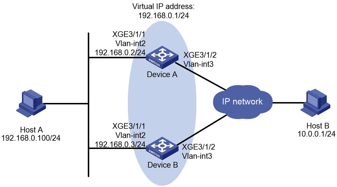
As shown in Figure 1, configure a VRRP group on Device A and Device B as the gateway for Host A to meet the following requirements:
· Device A operates as the master to forward packets from Host A to the external network.
· If Device A or its uplink interface fails, Host A can access the external network through Device B.
Analysis
To meet the network requirements, you must perform the following tasks:
· For Device A to become the master when it recovers from a failure, configure the preemptive mode for the VRRP group.
· For Device A to decrease its priority and become a backup when its uplink interface fails, configure VRRP tracking on Device A.
· To avoid frequent role change in the VRRP group, set a preemption delay.
Restrictions and guidelines
When you configure a single VRRP group, follow these restrictions and guidelines:
· The virtual IP address of a VRRP group cannot be any of the following addresses:
¡ All-zero address (0.0.0.0).
¡ Broadcast address (255.255.255.255).
¡ Loopback address.
¡ IP address of other than Class A, Class B, and Class C.
¡ Invalid IP address (for example, 0.0.0.1).
· For Host A to access the external network, make sure the following IP addresses are on the same subnet:
¡ The virtual IP address of the VRRP group.
¡ The downlink interface IP addresses of the VRRP group members.
· IPv4 VRRP can use VRRPv2 or VRRPv3 (default version). For a VRRP group to operate correctly, make sure the VRRP versions on all devices in the VRRP group are the same.
· Removal of the VRRP group on the IP address owner causes IP address collision. To avoid a collision, change the IP address of the interface on the IP address owner before you remove the VRRP group from the interface.
· Configure the same virtual IP addresses for each device in the VRRP group.
· Make sure the decreased priority of the master is lower than the priority of all the other devices in the VRRP group. Another device in the group can then be elected as the master.
Procedures
Configuring Device A
# Assign an IP address to Ten-GigabitEthernet 3/1/1.
[DeviceA] interface ten-gigabitEthernet 3/1/1
[DeviceA-Ten-GigabitEthernet3/1/1] ip address 192.168.0.2 24
# Create VRRP group 1, and set its virtual IP address to 192.168.0.1.
[DeviceA-Ten-GigabitEthernet3/1/1] vrrp vrid 1 virtual-ip 192.168.0.1
# Set the priority of Device A to 110 in VRRP group 1. Device A has a higher priority than Device B in VRRP group 1, so Device A can become the master.
[DeviceA-Ten-GigabitEthernet3/1/1] vrrp vrid 1 priority 110
# Configure Device A to operate in preemptive mode, and set the preemption delay to 500 centiseconds.
[DeviceA-Ten-GigabitEthernet3/1/1] vrrp vrid 1 preempt-mode delay 500
[DeviceA-Ten-GigabitEthernet3/1/1] quit
# Create track entry 1 to monitor the link status of the uplink interface Ten-GigabitEthernet 3/1/2.
[DeviceA] track 1 interface ten-gigabitethernet 3/1/2
# Associate VRRP group 1 with track entry 1 to decrease the weight of Device A by 50 when the track entry transits to Negative.
[DeviceA] interface ten-gigabitEthernet 3/1/1
[DeviceA-Ten-GigabitEthernet3/1/1] vrrp vrid 1 track 1 priority reduced 50
[DeviceA-Ten-GigabitEthernet3/1/1] quit
Configuring Device B
# Assign an IP address to Ten-GigabitEthernet 3/1/1.
[DeviceB] interface ten-gigabitethernet 3/1/1
[DeviceB-Ten-GigabitEthernet3/1/1] ip address 192.168.0.3 24
# Create VRRP group 1, and set its virtual IP address to 192.168.0.1.
[DeviceB-Ten-GigabitEthernet3/1/1] vrrp vrid 1 virtual-ip 192.168.0.1
# Set the priority of Device B to 100 in VRRP group 1.
[DeviceB-Ten-GigabitEthernet3/1/1] vrrp vrid 1 priority 100
# Configure Device B to operate in preemptive mode, and set the preemption delay to 500 centiseconds.
[DeviceB-Ten-GigabitEthernet3/1/1] vrrp vrid 1 preempt-mode delay 500
[DeviceB-Ten-GigabitEthernet3/1/1] quit
Verifying the configuration
1. Verify that Host A can ping Host B. (Details not shown.)
2. Verify that Device A is operating as the master in VRRP group 1 to forward packets from Host A to Host B.
# Display detailed information about VRRP group 1 on Device A.
[DeviceA] display vrrp verbose
IPv4 virtual router information:
Running mode : Standard
Total number of virtual routers : 1
Interface Ten-GigabitEthernet3/1/1
VRID : 1 Adver timer : 100 centiseconds
Admin status : Up State : Master
Config pri : 110 Running pri : 110
Preempt mode : Yes Delay time : 500 centiseconds
Auth type : None
Virtual IP : 192.168.0.1
Virtual MAC : 0000-5e00-0101
Master IP : 192.168.0.2
VRRP track information:
Track object : 1 State : Positive Pri reduced : 50
# Display detailed information about VRRP group 1 on Device B.
[DeviceB] display vrrp verbose
IPv4 virtual router information:
Running mode : Standard
Total number of virtual routers : 1
Interface Ten-GigabitEthernet3/1/1
VRID : 1 Adver timer : 100 centiseconds
Admin status : Up State : Backup
Config pri : 100 Running pri : 100
Preempt mode : Yes Delay time : 500 centiseconds
Become master : 412 milliseconds left
Auth type : None
Virtual IP : 192.168.0.1
Master IP : 192.168.0.2
3. Disconnect the link between Host A and Device A, and verify that Host A can still ping Host B. (Details not shown.)
4. Verify that Device B takes over to forward packets from Host A to Host B when Device A fails.
[DeviceB] display vrrp verbose
IPv4 virtual router information:
Running mode : Standard
Total number of virtual routers : 1
Interface Ten-GigabitEthernet3/1/1
VRID : 1 Adver timer : 100 centiseconds
Admin status : Up State : Master
Config pri : 100 Running pri : 100
Preempt mode : Yes Delay time : 500 centiseconds
Auth type : None
Virtual IP : 192.168.0.1
Virtual MAC : 0000-5e00-0101
Master IP : 192.168.0.3
5. Verify that Device A becomes the master to forward packets from Host A to Host B after Device A recovers.
[DeviceA] display vrrp verbose
IPv4 virtual router information:
Running mode : Standard
Total number of virtual routers : 1
Interface Ten-GigabitEthernet3/1/1
VRID : 1 Adver timer : 100 centiseconds
Admin status : Up State : Master
Config pri : 110 Running pri : 110
Preempt mode : Yes Delay time : 500 centiseconds
Auth type : None
Virtual IP : 192.168.0.1
Virtual MAC : 0000-5e00-0101
Master IP : 192.168.0.2
VRRP track information:
Track object : 1 State : Positive Pri reduced : 50
Configuration files
· Device A:
#
interface Ten-GigabitEthernet3/1/1
port link-mode route
ip address 192.168.0.2 255.255.255.0
vrrp vrid 1 virtual-ip 192.168.0.1
vrrp vrid 1 priority 110
vrrp vrid 1 preempt-mode delay 500
vrrp vrid 1 track 1 priority reduced 50
#
track 1 interface ten-gigabitethernet 3/1/2
#
· Device B:
#
interface Ten-GigabitEthernet3/1/1
port link-mode route
ip address 192.168.0.3 255.255.255.0
vrrp vrid 1 virtual-ip 192.168.0.1
vrrp vrid 1 priority 100
vrrp vrid 1 preempt-mode delay 500
#
Example: Configuring multiple VRRP groups
Network configuration
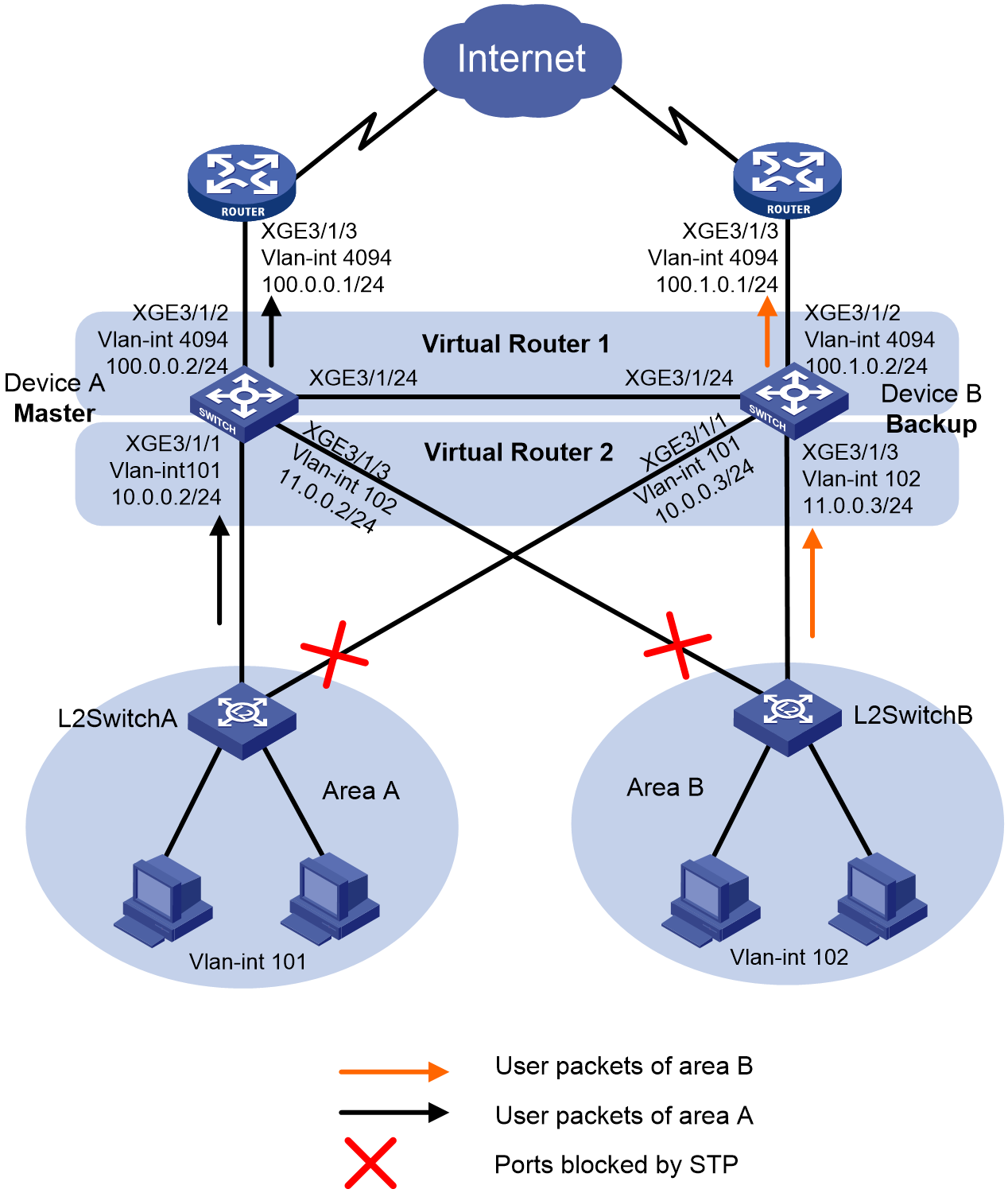
As shown in Figure 2, configure two VRRP groups on Device A and Device B as gateways for internal hosts to meet the following requirements:
· Device A operates as the master of VRRP group 1 to forward packets from Area A, and Device B operates as the master of VRRP group 2 to forward packets from Area B. When one of the devices fails, the other device provides gateway service for both areas.
· If the uplink interface of one device fails, hosts can access the external network through the other device.
Analysis
To avoid frequent role change in the VRRP group, set a preemption delay.
Restrictions and guidelines
When you configure multiple VRRP groups, follow these restrictions and guidelines:
· The virtual IP address of a VRRP group cannot be any of the following addresses:
¡ All-zero address (0.0.0.0).
¡ Broadcast address (255.255.255.255).
¡ Loopback address.
¡ IP address of other than Class A, Class B, and Class C.
¡ Invalid IP address (for example, 0.0.0.1).
· IPv4 VRRP can use VRRPv2 or VRRPv3 (default version). For a VRRP group to operate correctly, make sure the VRRP versions on all devices in the VRRP group are the same.
· Removal of the VRRP group on the IP address owner causes IP address collision. To avoid a collision, change the IP address of the interface on the IP address owner before you remove the VRRP group from the interface.
· Make sure the decreased priority of the master is lower than the priority of all the other devices in the VRRP group. Another device in the group can then be elected as the master.
· Make sure the following configurations are the same on the members of a VRRP group:
¡ Number of virtual IP addresses.
¡ Virtual IP addresses.
¡ Advertisement interval.
Procedures
Configuring Device A
# Assign an IP address to Ten-GigabitEthernet 3/1/1.
<DeviceA> system-view
[DeviceA] interface ten-gigabitethernet 3/1/1
[DeviceA-Ten-GigabitEthernet3/1/1] ip address 10.0.0.2 24
# Assign IP addresses to other interfaces of Device A. (Details not shown.)
# Create VRRP group 1, and set its virtual IP address to 10.0.0.1.
[DeviceA-Ten-GigabitEthernet3/1/1] vrrp vrid 1 virtual-ip 10.0.0.1
# Set the priority of Device A to 120 in VRRP group 1. Device A has a higher priority than Device B in VRRP group 1, so Device A can become the master.
[DeviceA-Ten-GigabitEthernet3/1/1] vrrp vrid 1 priority 120
# Configure Device A to operate in preemptive mode, and set the preemption delay to 500 centiseconds.
[DeviceA-Ten-GigabitEthernet3/1/1] vrrp vrid 1 preempt-mode delay 500
[DeviceA-Ten-GigabitEthernet3/1/1] quit
# Create VRRP group 2, and set its virtual IP address to 11.0.0.1.
[DeviceA] interface ten-gigabitethernet 3/1/3
[DeviceA-Ten-GigabitEthernet3/1/3] vrrp vrid 2 virtual-ip 11.0.0.1
# Configure Device A to operate in preemptive mode, and set the preemption delay to 500 centiseconds.
[DeviceA-Ten-GigabitEthernet3/1/3] vrrp vrid 2 preempt-mode delay 500
[DeviceA-Ten-GigabitEthernet3/1/3] quit
# Create track entry 1 to monitor the link status of the uplink interface Ten-GigabitEthernet 3/1/2.
[DeviceA] track 1 interface ten-gigabitethernet 3/1/2
# Associate VRRP group 1 with track entry 1 to decrease the weight of Device A by 50 when the track entry transits to Negative.
[DeviceA] interface ten-gigabitEthernet 3/1/1
[DeviceA-Ten-GigabitEthernet3/1/1] vrrp vrid 1 track 1 priority reduced 50
[DeviceA-Ten-GigabitEthernet3/1/1] quit
Configuring Device B
# Assign an IP address to Ten-GigabitEthernet 3/1/1.
<DeviceB> system-view
[DeviceB] interface ten-gigabitEthernet 3/1/1
[DeviceB-Ten-GigabitEthernet3/1/1] ip address 10.0.0.3 24
# Assign IP addresses to other VLAN interfaces of Device B. (Details not shown.)
# Create VRRP group 1, and set its virtual IP address to 10.0.0.1.
[DeviceB-Ten-GigabitEthernet3/1/1] vrrp vrid 1 virtual-ip 10.0.0.1
# Configure Device B to operate in preemptive mode, and set the preemption delay to 500 centiseconds.
[DeviceB-Ten-GigabitEthernet3/1/1] vrrp vrid 1 preempt-mode delay 500
[DeviceB-Ten-GigabitEthernet3/1/1] quit
# Create VRRP group 2, and set its virtual IP address to 11.0.0.1.
[DeviceB] interface ten-gigabitethernet 3/1/3
[DeviceB-Ten-GigabitEthernet3/1/3] vrrp vrid 2 virtual-ip 11.0.0.1
# Set the priority of Device B to 120 in VRRP group 2. Device B has a higher priority than Device A in VRRP group 2, so Device B can become the master.
[DeviceB-Ten-GigabitEthernet3/1/3] vrrp vrid 2 priority 120
# Configure Device B to operate in preemptive mode, and set the preemption delay to 500 centiseconds.
[DeviceB-Ten-GigabitEthernet3/1/3] vrrp vrid 2 preempt-mode delay 500
[DeviceB-Ten-GigabitEthernet3/1/3] quit
# Create track entry 2 to monitor the link status of the uplink interface Ten-GigabitEthernet 3/1/2.
[DeviceB] track 2 interface ten-gigabitethernet 3/1/2
# Associate VRRP group 2 with track entry 2 to decrease the weight of Device A by 50 when the track entry transits to Negative.
[DeviceB] interface ten-gigabitEthernet 3/1/3
[DeviceB-Ten-GigabitEthernet3/1/3] vrrp vrid 2 track 2 priority reduced 50
[DeviceB-Ten-GigabitEthernet3/1/3] quit
Verifying the configuration
1. Verify that the hosts in Area A and Area B can ping the external network.
# Ping 100.0.0.1 from Host A in Area A.
<host A> ping 100.0.0.1
PING 100.0.0.1 (100.0.0.1): 56 data bytes
56 bytes from 100.0.0.1: seq=0 ttl=128 time=22.43 ms
56 bytes from 100.0.0.1: seq=1 ttl=128 time=7.17 ms
56 bytes from 100.0.0.1: seq=2 ttl=128 time=8.91 ms
56 bytes from 100.0.0.1: seq=3 ttl=128 time=7.45 ms
56 bytes from 100.0.0.1: seq=4 ttl=128 time=9.11 ms
--- 100.0.0.1 ping statistics ---
5 packets transmitted, 5 packets received, 0% packet loss
round-trip min/avg/max = 7.17/11.01/22.43 ms
# Ping 100.1.0.1 from Host C in Area B.
<host C> ping 100.1.0.1
PING 100.1.0.1 (100.1.0.1): 56 data bytes
56 bytes from 100.1.0.1: seq=0 ttl=128 time=22.43 ms
56 bytes from 100.1.0.1: seq=1 ttl=128 time=7.17 ms
56 bytes from 100.1.0.1: seq=2 ttl=128 time=8.91 ms
56 bytes from 100.1.0.1: seq=3 ttl=128 time=7.45 ms
56 bytes from 100.1.0.1: seq=4 ttl=128 time=9.11 ms
--- 100.1.0.1 ping statistics ---
5 packets transmitted, 5 packets received, 0% packet loss
round-trip min/avg/max = 7.17/11.01/22.43 ms
2. Verify that Device A is operating as the master in VRRP group 1 and the backup in VRRP group 2. Device B is operating as the backup in VRRP group 1 and the master in VRRP group 2.
# Display detailed information about the VRRP groups on Device A.
[DeviceA] display vrrp verbose
IPv4 virtual router information:
Running mode : Standard
Total number of virtual routers : 2
Interface Ten-GigabitEthernet3/1/1
VRID : 1 Adver Timer : 100 centiseconds
Admin status : Up State : Master
Config pri : 120 Running pri : 120
Preempt mode : Yes Delay time : 500 centiseconds
Auth type : None
Virtual IP : 10.0.0.1
Virtual MAC : 0000-5e00-0101
Master IP : 10.0.0.2
VRRP track information:
Track object : 1 State : Positive Pri reduced : 50
Interface Ten-GigabitEthernet3/1/3
VRID : 2 Adver timer : 100 centiseconds
Admin status : Up State : Backup
Config pri : 100 Running pri : 100
Preempt mode : Yes Delay time : 500 centiseconds
Auth type : None
Become master : 3550 milliseconds left
Virtual IP : 11.0.0.1
Master IP : 11.0.0.3
# Display detailed information about the VRRP groups on Device B.
[DeviceB] display vrrp verbose
IPv4 virtual router information:
Running mode : Standard
Total number of virtual routers : 2
Interface Ten-GigabitEthernet3/1/1
VRID : 1 Adver timer : 100 centiseconds
Admin status : Up State : Backup
Config pri : 100 Running pri : 100
Preempt mode : Yes Delay time : 500 centiseconds
Auth type : None
Become master : 3500 milliseconds left
Virtual IP : 10.0.0.1
Master IP : 10.0.0.2
Interface Ten-GigabitEthernet3/1/3
VRID : 2 Adver timer : 100 centiseconds
Admin status : Up State : Master
Config pri : 120 Running pri : 120
Preempt mode : Yes Delay time : 500 centiseconds
Auth type : None
Virtual IP : 11.0.0.1
Virtual MAC : 0000-5e00-0102
Master IP : 11.0.0.3
VRRP track information:
Track object : 2 State : Positive Pri reduced : 50
3. Verify that Device B becomes the master in VRRP group 1 when Device A fails.
[DeviceB] display vrrp verbose
IPv4 virtual router information:
Running mode : Standard
Total number of virtual routers : 2
Interface Ten-GigabitEthernet3/1/1
VRID : 1 Adver timer : 100 centiseconds
Admin status : Up State : Master
Config pri : 100 Running pri : 100
Preempt mode : Yes Delay time : 500 centiseconds
Auth type : None
Virtual IP : 10.0.0.1
Virtual MAC : 0000-5e00-0101
Master IP : 10.0.0.3
Interface Ten-GigabitEthernet3/1/3
VRID : 2 Adver timer : 100 centiseconds
Admin status : Up State : Master
Config pri : 120 Running pri : 120
Preempt mode : Yes Delay time : 500 centiseconds
Auth type : None
Virtual IP : 11.0.0.1
Virtual MAC : 0000-5e00-0102
Master IP : 11.0.0.3
VRRP track information:
Track object : 2 State : Positive Pri reduced : 50
4. Verify that Device A becomes the master in VRRP group 1 after it recovers.
[DeviceA] display vrrp verbose
IPv4 virtual router information:
Running mode : Standard
Total number of virtual routers : 2
Interface Ten-GigabitEthernet3/1/1
VRID : 1 Adver timer : 100 centiseconds
Admin status : Up State : Master
Config pri : 120 Running pri : 120
Preempt mode : Yes Delay time : 500 centiseconds
Auth type : None
Virtual IP : 10.0.0.1
Virtual MAC : 0000-5e00-0101
Master IP : 10.0.0.2
VRRP track information:
Track object : 1 State : Positive Pri reduced : 50
Interface Ten-GigabitEthernet3/1/3
VRID : 2 Adver timer : 100 centiseconds
Admin status : Up State : Backup
Config pri : 100 Running pri : 100
Preempt mode : Yes Delay time : 500 centiseconds
Become master : 3550 milliseconds left
Auth type : None
Virtual IP : 11.0.0.1
Master IP : 11.0.0.3
Configuration files
· Device A:
#
interface Ten-GigabitEthernet3/1/1
port link-mode route
ip address 10.0.0.2 255.255.255.0
vrrp vrid 1 virtual-ip 10.0.0.1
vrrp vrid 1 priority 120
vrrp vrid 1 preempt-mode delay 500
vrrp vrid 1 track 1 priority reduced 50
#
interface Ten-GigabitEthernet3/1/2
port link-mode route
ip address 100.0.0.2 255.255.255.0
#
interface Ten-GigabitEthernet3/1/3
port link-mode route
ip address 11.0.0.2 255.255.255.0
vrrp vrid 2 virtual-ip 11.0.0.1
vrrp vrid 2 preempt-mode delay 500
#
track 1 interface ten-gigabitethernet 3/1/2
#
· Device B:
#
interface Ten-GigabitEthernet3/1/1
port link-mode route
ip address 10.0.0.3 255.255.255.0
vrrp vrid 1 virtual-ip 10.0.0.1
vrrp vrid 1 preempt-mode delay 500
#
interface Ten-GigabitEthernet3/1/2
port link-mode route
ip address 100.1.0.2 255.255.255.0
#
interface Ten-GigabitEthernet3/1/3
port link-mode route
ip address 11.0.0.3 255.255.255.0
vrrp vrid 2 priority 120
vrrp vrid 2 preempt-mode delay 500
vrrp vrid 2 track 2 priority reduced 50
#
track 2 interface ten-gigabitethernet 3/1/2
#
Example: Configuring VRRP load balancing
Network configuration
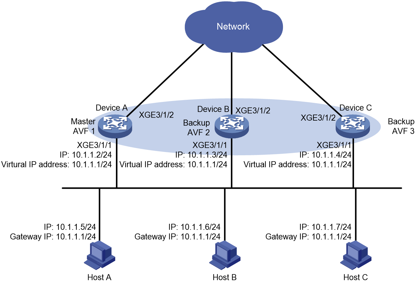
As shown in Figure 3, configure a load-balanced VRRP group on Device A, Device B, and Device C as the gateway for the hosts to meet the following requirements:
· Packets from the hosts are load balanced among the devices.
· If one device fails, hosts can access the external network through the other devices.
Analysis
To meet the network requirements, you must perform the following tasks:
· To avoid frequent role change in the VRRP group, set a preemption delay.
· For traffic to be switched to the other two devices when the uplink interface of one device fails, configure VF tracking on Device A, Device B, and Device C. When the uplink interface of one device fails, the weights of the VFs (including the AVF) on the device decrease by the specified value.
· For the failed device to become the master when it recovers, configure the preemptive mode for the VRRP group.
Restrictions and guidelines
When you configure VRRP load balancing, follow these restrictions and guidelines:
· The virtual IP address of a VRRP group cannot be any of the following addresses:
¡ All-zero address (0.0.0.0).
¡ Broadcast address (255.255.255.255).
¡ Loopback address.
¡ IP address of other than Class A, Class B, and Class C.
¡ Invalid IP address (for example, 0.0.0.1).
· For the hosts to access the external network, make sure the following IP addresses are on the same subnet:
¡ The virtual IP address of the VRRP group.
¡ The downlink interface IP addresses of the VRRP group members.
· IPv4 VRRP can use VRRPv2 or VRRPv3 (default version). For a VRRP group to operate correctly, make sure the VRRP versions on all devices in the VRRP group are the same.
· In load balancing mode, the virtual IP address of a VRRP group cannot be the IP address of any interface in the VRRP group. Otherwise, VRRP load balancing cannot operate correctly.
· If the uplink interface of the VF owner fails, an LVF must take over as the AVF. The switchover occurs when the weight of the VF owner drops below the lower limit of failure. This requires the reduced weight for the VF owner to be higher than 245.
· Configure the same virtual IP addresses for each device in the VRRP group.
· Make sure the decreased priority of the master is lower than the priority of all the other devices in the VRRP group. Another device in the group can then be elected as the master.
Procedures
Configuring Device A
1. Configure the interfaces:
<DeviceA> system-view
[DeviceA] interface ten-gigabitEthernet 3/1/1
[DeviceA-Ten-GigabitEthernet3/1/1] ip address 10.1.1.2 24
[DeviceA-Ten-GigabitEthernet3/1/1] quit
2. Configure VRRP:
# Configure VRRP to operate in load balancing mode.
[DeviceA] vrrp mode load-balance
# Create VRRP group 1, and set its virtual IP address to 10.1.1.1.
[DeviceA] interface ten-gigabitethernet 3/1/1
[DeviceA-Ten-GigabitEthernet3/1/1] vrrp vrid 1 virtual-ip 10.1.1.1
# Set the priority of Device A to 120 in VRRP group 1. Device A has the highest priority in VRRP group 1, so Device A can become the master.
[DeviceA-Ten-GigabitEthernet3/1/1] vrrp vrid 1 priority 120
# Configure Device A to operate in preemptive mode, and set the preemption delay to 500 centiseconds.
[DeviceA-Ten-GigabitEthernet3/1/1] vrrp vrid 1 preempt-mode delay 500
[DeviceA-Ten-GigabitEthernet3/1/1] quit
3. Configure Track:
# Create track entry 1 to monitor the link status of the uplink interface Ten-GigabitEthernet 3/1/2. If the uplink interface fails, the track entry transits to Negative.
[DeviceA] track 1 interface ten-gigabitethernet 3/1/2
# Configure the VFs in VRRP group 1 to monitor track entry 1, and decrease their weights by 250 when the track entry transits to Negative.
[DeviceA] interface ten-gigabitEthernet 3/1/1
[DeviceA-Ten-GigabitEthernet3/1/1] vrrp vrid 1 track 1 weight reduced 250
[DeviceA-Ten-GigabitEthernet3/1/1] quit
Configuring Device B
1. Configure the interfaces:
<DeviceB> system-view
[DeviceB] interface ten-gigabitEthernet 3/1/1
[DeviceB-Ten-GigabitEthernet3/1/1] ip address 10.1.1.3 24
[DeviceB-Ten-GigabitEthernet3/1/1] quit
2. Configure VRRP:
# Configure VRRP to operate in load balancing mode.
[DeviceB] vrrp mode load-balance
# Create VRRP group 1, and set its virtual IP address to 10.1.1.1.
[DeviceB] interface ten-gigabitethernet 3/1/1
[DeviceB-Ten-GigabitEthernet3/1/1] vrrp vrid 1 virtual-ip 10.1.1.1
# Set the priority of Device B to 110 in VRRP group 1. Device B has a higher priority than Device C in VRRP group 1, so Device B can become the master when Device A fails.
[DeviceB-Ten-GigabitEthernet3/1/1] vrrp vrid 1 priority 110
# Configure Device B to operate in preemptive mode, and set the preemption delay to 500 centiseconds.
[DeviceB-Ten-GigabitEthernet3/1/1] vrrp vrid 1 preempt-mode delay 500
[DeviceB-Ten-GigabitEthernet3/1/1] quit
3. Configure Track:
# Create track entry 1 to monitor the link status of the uplink interface Ten-GigabitEthernet3 /0/2. When the uplink interface fails, the track entry transits to Negative.
[DeviceB] track 1 interface ten-gigabitethernet 3/1/2
# Configure the VFs in VRRP group 1 to monitor track entry 1, and decrease their weights by 250 when the track entry transits to Negative.
[DeviceB] interface ten-gigabitEthernet 3/1/1
[DeviceB-Ten-GigabitEthernet3/1/1] vrrp vrid 1 track 1 weight reduced 250
[DeviceB-Ten-GigabitEthernet3/1/1] quit
Configuring Device C
1. Configure the interfaces:
<DeviceC> system-view
[DeviceC] interface ten-gigabitEthernet 3/1/1
[DeviceC-Ten-GigabitEthernet3/1/1] ip address 10.1.1.4 24
[DeviceC-Ten-GigabitEthernet3/1/1] quit
2. Configure VRRP:
# Configure VRRP to operate in load balancing mode.
[DeviceC] vrrp mode load-balance
# Create VRRP group 1, and set its virtual IP address to 10.1.1.1.
[DeviceC] interface ten-gigabitethernet 3/1/1
[DeviceC-Ten-GigabitEthernet3/1/1] vrrp vrid 1 virtual-ip 10.1.1.1
# Configure Device C to operate in preemptive mode, and set the preemption delay to 500 centiseconds.
[DeviceC-Ten-GigabitEthernet3/1/1] vrrp vrid 1 preempt-mode delay 500
[DeviceC-Ten-GigabitEthernet3/1/1] quit
3. Configure Track:
# Create track entry 1 to monitor the link status of the uplink interface Ten-GigabitEthernet 3/1/2. When the uplink interface fails, the track entry transits to Negative.
[DeviceC] track 1 interface ten-gigabitethernet 3/1/2
# Configure the VFs in VRRP group 1 to monitor track entry 1, and decrease their weights by 250 when the track entry transits to Negative.
[DeviceC] interface ten-gigabitEthernet 3/1/1
[DeviceC-Ten-GigabitEthernet3/1/1] vrrp vrid 1 track 1 weight reduced 250
[DeviceC-Ten-GigabitEthernet3/1/1] quit
Verifying the configuration
1. Verify that Host A can ping the external network. (Details not shown.)
2. Verify that Device A is operating as the master and Device B and Device C as the backups in VRRP group 1. Each of the three devices has one AVF and two LVFs.
# Display detailed information about VRRP group 1 on Device A.
[DeviceA] display vrrp verbose
IPv4 virtual device information:
Running mode : Load balance
Total number of virtual routers : 1
Interface Ten-GigabitEthernet3/1/1
VRID : 1 Adver timer : 100 centiseconds
Admin status : Up State : Master
Config pri : 120 Running pri : 120
Preempt mode : Yes Delay time : 500 centiseconds
Auth type : None
Virtual IP : 10.1.1.1
Member IP list : 10.1.1.2 (Local, Master)
10.1.1.3 (Backup)
10.1.1.4 (Backup)
Forwarder information: 3 Forwarders 1 Active
Config weight : 255
Running weight : 255
Forwarder 01
State : Active
Virtual MAC : 000f-e2ff-0011 (Owner)
Owner ID : 0000-5e01-1101
Priority : 255
Active : local
Forwarder 02
State : Listening
Virtual MAC : 000f-e2ff-0012 (Learnt)
Owner ID : 0000-5e01-1103
Priority : 127
Active : 10.1.1.3
Forwarder 03
State : Listening
Virtual MAC : 000f-e2ff-0013 (Learnt)
Owner ID : 0000-5e01-1105
Priority : 127
Active : 10.1.1.4
Forwarder weight track information:
Track object : 1 State : Positive Weight reduced : 250
# Display detailed information about VRRP group 1 on Device B.
[DeviceB] display vrrp verbose
IPv4 virtual device information:
Running mode : Load balance
Total number of virtual routers : 1
Interface Ten-GigabitEthernet3/1/1
VRID : 1 Adver timer : 100 centiseconds
Admin status : Up State : Backup
Config pri : 110 Running pri : 110
Preempt node : Yes Delay time : 500 centiseconds
Auth type : None
Virtual IP : 10.1.1.1
Member IP list : 10.1.1.3 (Local, Backup)
10.1.1.2 (Master)
10.1.1.4 (Backup)
Forwarder information: 3 Forwarders 1 Active
Config weight : 255
Running weight : 255
Forwarder 01
State : Listening
Virtual MAC : 000f-e2ff-0011 (Learnt)
Owner ID : 0000-5e01-1101
Priority : 127
Active : 10.1.1.2
Forwarder 02
State : Active
Virtual MAC : 000f-e2ff-0012 (Owner)
Owner ID : 0000-5e01-1103
Priority : 255
Active : local
Forwarder 03
State : Listening
Virtual MAC : 000f-e2ff-0013 (Learnt)
Owner ID : 0000-5e01-1105
Priority : 127
Active : 10.1.1.4
Forwarder weight track information:
Track object : 1 State : Positive Weight reduced : 250
# Display detailed information about VRRP group 1 on Device C.
[DeviceC] display vrrp verbose
IPv4 virtual device information:
Running mode : Load balance
Total number of virtual routers : 1
Interface Ten-GigabitEthernet3/1/1
VRID : 1 Adver timer : 100 centiseconds
Admin status : Up State : Backup
Config pri : 100 Running pri : 100
Preempt mode : Yes Delay time : 500 centiseconds
Auth type : None
Virtual IP : 10.1.1.1
Member IP list : 10.1.1.4 (Local, Backup)
10.1.1.2 (Master)
10.1.1.3 (Backup)
Forwarder information: 3 Forwarders 1 Active
Config weight : 255
Running weight : 255
Forwarder 01
State : Listening
Virtual MAC : 000f-e2ff-0011 (Learnt)
Owner ID : 0000-5e01-1101
Priority : 127
Active : 10.1.1.2
Forwarder 02
State : Listening
Virtual MAC : 000f-e2ff-0012 (Learnt)
Owner ID : 0000-5e01-1103
Priority : 127
Active : 10.1.1.3
Forwarder 03
State : Active
Virtual MAC : 000f-e2ff-0013 (Owner)
Owner ID : 0000-5e01-1105
Priority : 255
Active : local
Forwarder weight track information:
Track object : 1 State : Positive Weight reduced : 250
3. Verify that AVF switchover can be performed when the uplink interface of Device A fails.
# Display detailed information about VRRP group 1 on Device A.
[DeviceA] display vrrp verbose
IPv4 virtual device information:
Running mode : Load balance
Total number of virtual routers : 1
Interface Ten-GigabitEthernet3/1/1
VRID : 1 Adver timer : 100 centiseconds
Admin status : Up State : Master
Config pri : 120 Running pri : 120
Preempt mode : Yes Delay time : 500 centiseconds
Auth type : None
Virtual IP : 10.1.1.1
Member IP list : 10.1.1.2 (Local, Master)
10.1.1.3 (Backup)
10.1.1.4 (Backup)
Forwarder Information: 3 Forwarders 0 Active
Config weight : 255
Running weight : 5
Forwarder 01
State : Initialize
Virtual MAC : 000f-e2ff-0011 (Owner)
Owner ID : 0000-5e01-1101
Priority : 0
Active : 10.1.1.4
Forwarder 02
State : Initialize
Virtual MAC : 000f-e2ff-0012 (Learnt)
Owner ID : 0000-5e01-1103
Priority : 0
Active : 10.1.1.3
Forwarder 03
State : Initialize
Virtual MAC : 000f-e2ff-0013 (Learnt)
Owner ID : 0000-5e01-1105
Priority : 0
Active : 10.1.1.4
Forwarder weight track information:
Track object : 1 State : Negative Weight reduced : 250
# Display detailed information about VRRP group 1 on Device C.
[DeviceC] display vrrp verbose
IPv4 virtual device information:
Running mode : Load balance
Total number of virtual routers : 1
Interface Ten-GigabitEthernet3/1/1
VRID : 1 Adver timer : 100 centiseconds
Admin status : Up State : Backup
Config pri : 100 Running pri : 100
Preempt mode : Yes Delay time : 500 centiseconds
Auth type : None
Become master : 3550 milliseconds left
Virtual IP : 10.1.1.1
Member IP list : 10.1.1.4 (Local, Backup)
10.1.1.2 (Master)
10.1.1.3 (Backup)
Forwarder information: 3 Forwarders 2 Active
Config weight : 255
Running weight : 255
Forwarder 01
State : Active
Virtual MAC : 000f-e2ff-0011 (Take Over)
Owner ID : 0000-5e01-1101
Priority : 85
Active : local
Redirect time : 93 seconds
Time-out time : 1293 seconds
Forwarder 02
State : Listening
Virtual MAC : 000f-e2ff-0012 (Learnt)
Owner ID : 0000-5e01-1103
Priority : 85
Active : 10.1.1.3
Forwarder 03
State : Active
Virtual MAC : 000f-e2ff-0013 (Owner)
Owner ID : 0000-5e01-1105
Priority : 255
Active : local
Forwarder weight track information:
Track object : 1 State : Positive Weight reduced : 250
The output shows that when the uplink interface of Device A fails, the weights of the VFs on Device A drop below the lower limit of failure. All VFs on Device A transit to Initialized state and cannot forward traffic. The VF for MAC address 000f-e2ff-0011 on Device C becomes the AVF to forward traffic.
4. #Verify that the VF for virtual MAC address 000f-e2ff-0011 is removed from Device C when the timeout timer (about 1800 seconds) expires. The VF no longer forwards the packets destined for the MAC address.
[DeviceC] display vrrp verbose
IPv4 virtual device information:
Running mode : Load balance
Total number of virtual routers : 1
Interface Ten-GigabitEthernet3/1/1
VRID : 1 Adver timer : 100 centiseconds
Admin status : Up State : Backup
Config pri : 100 Running pri : 100
Preempt mode : Yes Delay time : 500 centiseconds
Auth type : None
Become master : 3550 milliseconds left
Virtual IP : 10.1.1.1
Member IP list : 10.1.1.4 (Local, Backup)
10.1.1.2 (Master)
10.1.1.3 (Backup)
Forwarder information: 2 Forwarders 1 Active
Config weight : 255
Running weight : 255
Forwarder 02
State : Listening
Virtual MAC : 000f-e2ff-0012 (Learnt)
Owner ID : 0000-5e01-1103
Priority : 127
Active : 10.1.1.3
Forwarder 03
State : Active
Virtual MAC : 000f-e2ff-0013 (Owner)
Owner ID : 0000-5e01-1105
Priority : 255
Active : local
Forwarder weight track information:
Track object : 1 State : Positive Weight reduced : 250
5. Verify that Device B has a higher priority than Device C and becomes the master when Device A fails.
[DeviceB] display vrrp verbose
IPv4 standby information:
Run mode : Load balance
Run method : Virtual MAC
Total number of virtual routers : 1
Interface Ten-GigabitEthernet3/1/1
VRID : 1 Adver timer : 1 centiseconds
Admin status : Up State : Master
Config pri : 110 Running pri : 110
Preempt mode : Yes Delay time : 500 centiseconds
Auth type : None
Virtual IP : 10.1.1.1
Member IP list : 10.1.1.3 (Local, Master)
10.1.1.4 (Backup)
Forwarder information: 2 Forwarders 1 Active
Config weight : 255
Running weight : 255
Forwarder 02
State : Active
Virtual MAC : 000f-e2ff-0012 (Owner)
Owner ID : 0000-5e01-1103
Priority : 255
Active : local
Forwarder 03
State : Listening
Virtual MAC : 000f-e2ff-0013 (Learnt)
Owner ID : 0000-5e01-1105
Priority : 127
Active : 10.1.1.4
Forwarder weight track information:
Track object : 1 State : Positive Weight reduced : 250
Configuration files
· Device A:
#
vrrp mode load-balance
#
interface Ten-GigabitEthernet3/1/1
port link-mode route
ip address 10.1.1.2 255.255.255.0
vrrp vrid 1 virtual-ip 10.1.1.1
vrrp vrid 1 priority 120
vrrp vrid 1 preempt-mode delay 500
vrrp vrid 1 track 1 weight reduced 250
#
interface Ten-GigabitEthernet3/1/2
port link-mode route
#
track 1 interface Ten-GigabitEthernet3/1/2
#
· Device B:
#
vrrp mode load-balance
#
interface Ten-GigabitEthernet3/1/1
port link-mode route
ip address 10.1.1.3 255.255.255.0
vrrp vrid 1 virtual-ip 10.1.1.1
vrrp vrid 1 priority 110
vrrp vrid 1 preempt-mode delay 500
vrrp vrid 1 track 1 weight reduced 250
#
interface Ten-GigabitEthernet3/1/2
port link-mode route
#
track 1 interface Ten-GigabitEthernet3/1/2
#
· Device C:
#
vrrp mode load-balance
#
interface Ten-GigabitEthernet3/1/1
port link-mode route
ip address 10.1.1.4 255.255.255.0
vrrp vrid 1 virtual-ip 10.1.1.1
vrrp vrid 1 preempt-mode delay 500
vrrp vrid 1 track 1 weight reduced 250
#
interface Ten-GigabitEthernet3/1/2
port link-mode route
#
track 1 interface Ten-GigabitEthernet3/1/2
#
Example: Configuring subordinate VRRP groups to follow master VRRP groups for Layer 3 subinterfaces
Network configuration
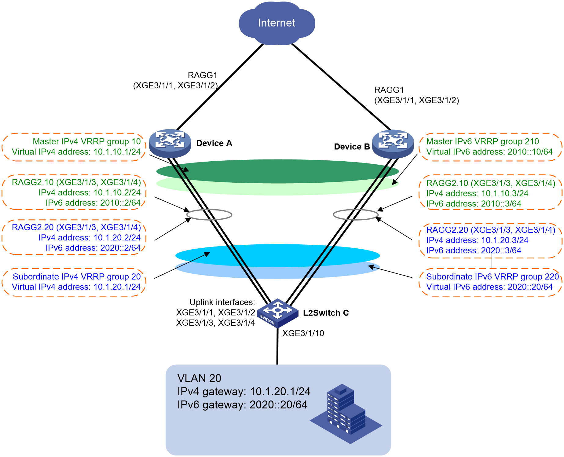
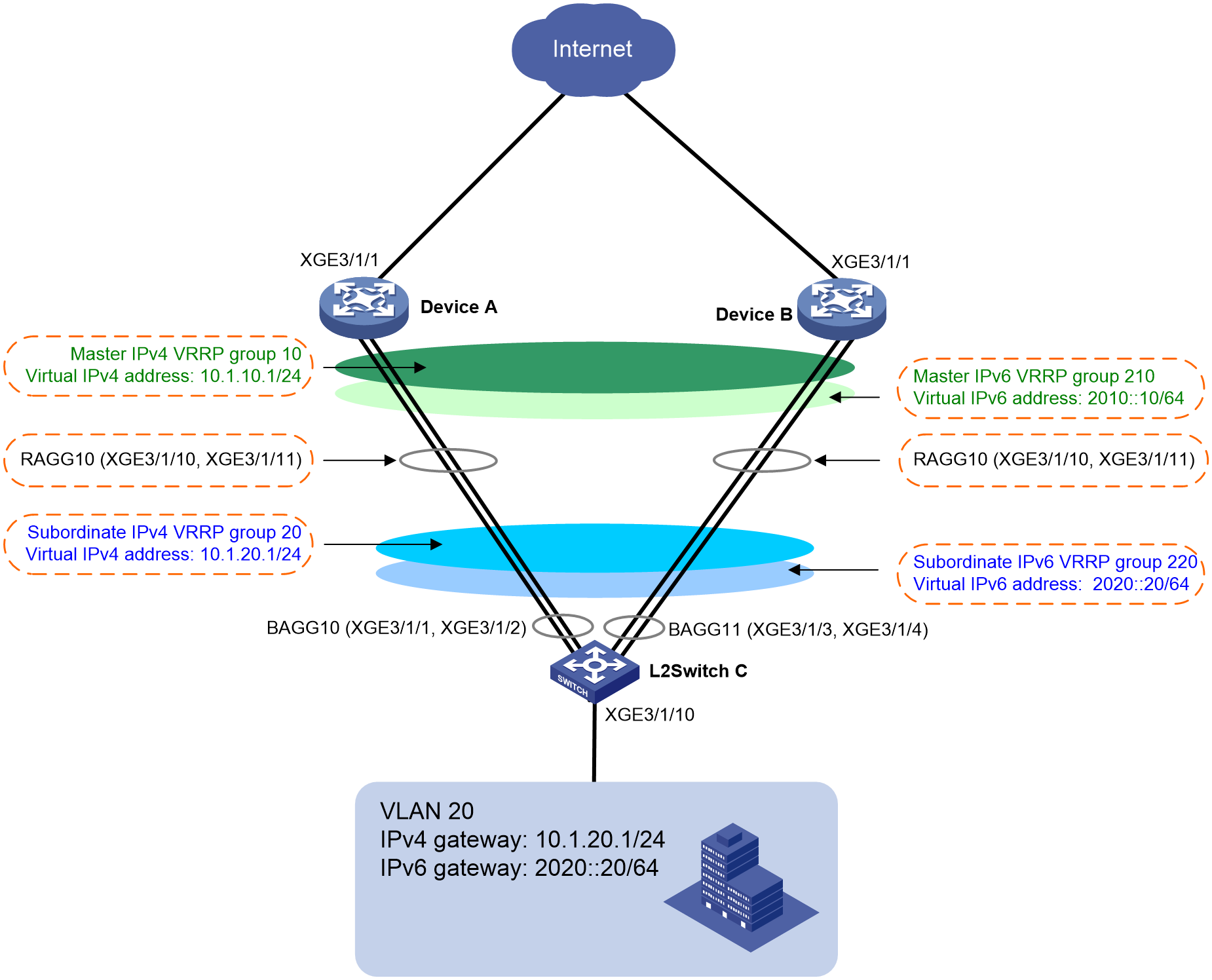
As shown in , in an IPv4 and IPv6 hybrid network, the hosts are connected to the gateways (Layer 3 devices) through a Layer 2 switch. To enhance network availability, perform the following tasks:
· Create master IPv4 VRRP group 10 to manage the state of the associated subordinate IPv4 VRRP group. Set the virtual IP address of master IPv4 VRRP group 10 to 10.1.10.1/24.
· Create master IPv6 VRRP group 210 to manage the state of the associated subordinate IPv6 VRRP group. Set the virtual IPv6 address of master IPv6 VRRP group 210 to 2010::10/64.
· Create IPv4 VRRP group 20 to provide gateway services for IPv4 devices in the LAN. Set the virtual IP address of IPv4 VRRP group 20 to 10.1.20.1/24.
· Create IPv6 VRRP group 220 to provide gateway services for IPv6 devices in the LAN. Set the virtual IPv6 address of IPv6 VRRP group 220 to 2020::20/64.
· Typically, Device A acts as the gateway to forward LAN traffic to the external network.
· When Device A or the associated uplink or downlink fails, Device B takes over to act as the gateway. When the fault is cleared, Device A acts as the gateway again.
Figure 4 Network diagram
Analysis
To meet the network requirements, you must perform the following tasks:
· Connect the uplink interfaces (RAGG1) of Device A and Device B to the Internet, and connect the downlink interfaces (RAGG2) of Device A and Device B to the Layer 2 switch.
· To reduce VRRP packets in the network and save downlink bandwidth, configure master VRRP groups and configure subordinate VRRP groups to follow the master VRRP groups. The state of the subordinate VRRP groups follows the state of the master groups.
· Configure master VRRP groups on aggregate subinterface RAGG2.10 of Device A and Device B. VLAN 10 is used to exchange VRRP packets through L2Switch C. Configure subordinate VRRP groups on aggregate subinterface RAGG2.20 of Device A and Device B to provide gateway services for hosts in VLAN 20. In addition, configure aggregate subinterface RAGG2.20 to terminate packets of VLAN 20.
· To implement load sharing between the master VRRP groups, configure the following settings:
¡ Configure a higher priority for Device A in the master IPv4 VRRP group. Then Device A becomes the master, and Device B becomes the backup in the VRRP group.
¡ Configure a higher priority for Device B in the master IPv6 VRRP group. Then Device B becomes the master, and Device A becomes the backup in the IPv6 VRRP group.
· Configure the preemptive mode and uplink tracking for the master VRRP groups. When the uplink of a master fails, the master can decrease its priority and become a backup.
· To avoid frequent role change in the master VRRP groups, set a preemption delay.
Restrictions and guidelines
When you configure subordinate VRRP groups to follow master VRRP groups for Layer 3 subinterfaces, follow these restrictions and guidelines:
· The virtual IP address of a VRRP group cannot be any of the following addresses:
¡ All-zero address (0.0.0.0).
¡ Broadcast address (255.255.255.255).
¡ Loopback address.
¡ IP address of other than Class A, Class B, and Class C.
¡ Invalid IP address (for example, 0.0.0.1).
· For hosts in the LAN to access the external network, make sure the following IP addresses are on the same subnet:
¡ The virtual IP address of the VRRP group.
¡ The downlink interface IP addresses of the VRRP group members.
· IPv4 VRRP can use VRRPv2 or VRRPv3 (default version). For a VRRP group to operate correctly, make sure the VRRP versions on all devices in the VRRP group are the same.
· Removal of the VRRP group on the IP address owner causes IP address collision. To avoid a collision, change the IP address of the interface on the IP address owner before you remove the VRRP group from the interface.
· Make sure the decreased priority of the master is lower than the priority of all the other devices in the VRRP group. Another device in the group can then be elected as the master.
· Make sure the following configurations are the same on the members of a VRRP group:
¡ Number of virtual IP addresses.
¡ Virtual IP addresses.
¡ Advertisement interval.
Procedures
Configuring Device A
1. Configure the uplink aggregate interface.
# Create uplink aggregate interface Route-Aggregation 1.
<DeviceA> system-view
[DeviceA] interface route-aggregation 1
[DeviceA-Route-Aggregation1] link-aggregation mode dynamic
[DeviceA-Route-Aggregation1] quit
# Add Ten-GigabitEthernet 3/1/1 and Ten-GigabitEthernet 3/1/2 to aggregation group 1.
[DeviceA] interface range ten-gigabitethernet 3/1/1 ten-gigabitethernet 3/1/2
[DeviceA-if-range] port link-aggregation group 1
[DeviceA-if-range] quit
2. Configure the downlink aggregate interface.
# Create downlink aggregate interface Route-Aggregation 2.
[DeviceA] interface route-aggregation 2
[DeviceA-Route-Aggregation2] link-aggregation mode dynamic
[DeviceA-Route-Aggregation2] quit
# Add Ten-GigabitEthernet 3/1/3 and Ten-GigabitEthernet 3/1/4 to aggregation group 2.
[DeviceA] interface range ten-gigabitethernet 3/1/3 ten-gigabitethernet 3/1/4
[DeviceA-if-range] port link-aggregation group 2
[DeviceA-if-range] quit
# Create aggregate subinterface Route-Aggregation 2.10, set its IPv4 address to 10.1.10.2/24 and its IPv6 address to 2010::2/64.
[DeviceA] interface route-aggregation 2.10
[DeviceA-Route-Aggregation2.10] ip address 10.1.10.2 24
[DeviceA-Route-Aggregation2.10] ipv6 address auto link-local
[DeviceA-Route-Aggregation2.10] ipv6 address 2010::2 64
# Configure Route-Aggregation 2.10 to terminate VLAN-tagged packets with outermost VLAN ID 10. The aggregate interface can then forward VRRP packets to Device B through the downlink Layer 2 switch.
[DeviceA-Route-Aggregation2.10] vlan-type dot1q vid 10
[DeviceA-Route-Aggregation2.10] quit
# Create aggregate subinterface Route-Aggregation 2.20, set its IPv4 address to 10.1.20.2/24 and its IPv6 address to 2020::2/64.
[DeviceA] interface route-aggregation 2.20
[DeviceA-Route-Aggregation2.20] ip address 10.1.20.2 24
[DeviceA-Route-Aggregation2.20] ipv6 address auto link-local
[DeviceA-Route-Aggregation2.20] ipv6 address 2020::2 64
# Configure Route-Aggregation 2.20 to terminate VLAN-tagged packets with outermost VLAN ID 20.
[DeviceA-Route-Aggregation2.20] vlan-type dot1q vid 20
[DeviceA-Route-Aggregation2.20] quit
3. Configure master IPv4 VRRP group 10 on Route-Aggregation 2.10.
# Create VRRP group 10, and set its virtual IP address to 10.1.10.1.
[DeviceA] interface route-aggregation 2.10
[DeviceA-Route-Aggregation2.10] vrrp vrid 10 virtual-ip 10.1.10.1
[DeviceA-Route-Aggregation2.10] vrrp vrid 10 name IPv4manager
# Set the priority of Device A to 120 in VRRP group 10. Device A has a higher priority than Device B (100) in VRRP group 10, so Device A can become the master.
[DeviceA-Route-Aggregation2.10] vrrp vrid 10 priority 120
# Configure Device A to operate in preemptive mode, and set the preemption delay to 12000 centiseconds.
[DeviceA-Route-Aggregation2.10] vrrp vrid 10 preempt-mode delay 12000
[DeviceA-Route-Aggregation2.10] quit
# Enable periodic sending of gratuitous ARP packets and set the sending interval to 120 seconds.
[DeviceA] vrrp send-gratuitous-arp interval 120
# Create track entry 1 to monitor the link status of the uplink aggregate interface Route-Aggregation 1. Associate VRRP group 10 with track entry 1 to decrease the weight of Device A by 50 when the track entry transits to Negative. (The track entry configuration is not required if multiple backup uplink links are available.)
[DeviceA] track 1 interface route-aggregation 1
[DeviceA-track-1] quit
[DeviceA] interface route-aggregation 2.10
[DeviceA-Route-Aggregation2.10] vrrp vrid 10 track 1 priority reduced 50
4. Configure master IPv6 VRRP group 210 on Route-Aggregation 2.10.
# Create IPv6 VRRP group 210, and set its virtual IPv6 address to 2010::10.
[DeviceA-Route-Aggregation2.10] vrrp ipv6 vrid 210 virtual-ip fe80::10 link-local
[DeviceA-Route-Aggregation2.10] vrrp ipv6 vrid 210 virtual-ip 2010::10
[DeviceA-Route-Aggregation2.10] vrrp ipv6 vrid 210 name IPv6manager
[DeviceA-Route-Aggregation2.10] quit
# Enable periodic sending of gratuitous ND packets and set the sending interval to 120 seconds.
[DeviceA] vrrp ipv6 send-nd interval 120
5. Configure IPv4 VRRP group 20 on Route-Aggregation 2.20.
# Create IPv4 VRRP group 20, and set its virtual IP address to 10.1.20.1.
[DeviceA] interface route-aggregation 2.20
[DeviceA-Route-Aggregation2.20] vrrp vrid 20 virtual-ip 10.1.20.1
# Configure IPv4 VRRP group 20 to follow master IPv4 VRRP group 10.
[DeviceA-Route-Aggregation2.20] vrrp vrid 20 follow IPv4manager
[DeviceA-Route-Aggregation2.20] quit
6. Configure IPv6 VRRP group 220 on Route-Aggregation 2.20.
# Create IPv6 VRRP group 220, and set its virtual IPv6 address to 2020::20/64.
[DeviceA] interface route-aggregation 2.20
[DeviceA-Route-Aggregation2.20] vrrp ipv6 vrid 220 virtual-ip fe80::20 link-local
[DeviceA-Route-Aggregation2.20] vrrp ipv6 vrid 220 virtual-ip 2020::20
# Configure IPv6 VRRP group 220 to follow master IPv6 VRRP group 210.
[DeviceA-Route-Aggregation2.20] vrrp ipv6 vrid 220 follow IPv6manager
[DeviceA-Route-Aggregation2.20] quit
7. Bring up associated interfaces.
[DeviceA] interface range route-aggregation 1 route-aggregation 2 ten-gigabitethernet 3/1/1 to ten-gigabitethernet 3/1/4
[DeviceA-if-range] undo shutdown
[DeviceA-if-range] quit
[DeviceA]
Configuring Device B
1. Configure the uplink aggregate interface.
# Create uplink aggregate interface Route-Aggregation 1.
<DeviceB> system-view
[DeviceB] interface route-aggregation 1
[DeviceB-Route-Aggregatio1] link-aggregation mode dynamic
[DeviceB-Route-Aggregation1] quit
# Add Ten-GigabitEthernet 3/1/1 and Ten-GigabitEthernet 3/1/2 to aggregation group 1.
[DeviceB] interface range ten-gigabitethernet 3/1/1 ten-gigabitethernet 3/1/2
[DeviceB-if-range] port link-aggregation group 1
[DeviceB-if-range] quit
2. Configure the downlink aggregate interface.
# Create downlink aggregate interface Route-Aggregation 2.
[DeviceB] interface route-aggregation 2
[DeviceB-Route-Aggregation2] link-aggregation mode dynamic
[DeviceB-Route-Aggregation2] quit
# Add Ten-GigabitEthernet 3/1/3 and Ten-GigabitEthernet 3/1/4 to aggregation group 2.
[DeviceB] interface range ten-gigabitethernet 3/1/3 ten-gigabitethernet 3/1/4
[DeviceB-if-range] port link-aggregation group 2
[DeviceB-if-range] quit
# Create aggregate subinterface Route-Aggregation 2.10, set its IPv4 address to 10.1.10.3/24 and its IPv6 address to 2010::3/64.
[DeviceB] interface route-aggregation 2.10
[DeviceB-Route-Aggregation2.10] ip address 10.1.10.3 24
[DeviceB-Route-Aggregation2.10] ipv6 address auto link-local
[DeviceB-Route-Aggregation2.10] ipv6 address 2010::3 64
# Configure Route-Aggregation 2.10 to terminate VLAN-tagged packets with outermost VLAN ID 10. The aggregate interface can then forward VRRP packets to Device A through the downlink Layer 2 switch.
[DeviceB-Route-Aggregation2.10] vlan-type dot1q vid 10
[DeviceB-Route-Aggregation2.10] quit
# Create aggregate subinterface Route-Aggregation 2.20, set its IPv4 address to 10.1.20.3/24 and its IPv6 address to 2020::3/64.
[DeviceB] interface route-aggregation 2.20
[DeviceB-Route-Aggregation2.20] ip address 10.1.20.3 24
[DeviceB-Route-Aggregation2.20] ipv6 address auto link-local
[DeviceB-Route-Aggregation2.20] ipv6 address 2020::3 64
# Configure Route-Aggregation 2.20 to terminate VLAN-tagged packets with outermost VLAN ID 20.
[DeviceB-Route-Aggregation2.20] vlan-type dot1q vid 20
[DeviceB-Route-Aggregation2.20] quit
3. Configure master IPv4 VRRP group 10 on Route-Aggregation 2.10.
# Create VRRP group 10, and set its virtual IP address to 10.1.10.1.
[DeviceB] interface route-aggregation 2.10
[DeviceB-Route-Aggregation2.10] vrrp vrid 10 virtual-ip 10.1.10.1
[DeviceB-Route-Aggregation2.10] vrrp vrid 10 name IPv4manager
# Enable periodic sending of gratuitous ARP packets and set the sending interval to 120 seconds.
[DeviceB-Route-Aggregation2.10] quit
[DeviceB] vrrp send-gratuitous-arp interval 120
4. Configure master IPv6 VRRP group 210 on Route-Aggregation 2.10.
# Create IPv6 VRRP group 210, and set its virtual IPv6 address to 2010::10.
[DeviceB] interface route-aggregation 2.10
[DeviceB-Route-Aggregation2.10] vrrp ipv6 vrid 210 virtual-ip fe80::10 link-local
[DeviceB-Route-Aggregation2.10] vrrp ipv6 vrid 210 virtual-ip 2010::10
[DeviceB-Route-Aggregation2.10] vrrp ipv6 vrid 210 name IPv6manager
# Set the priority of Device B to 120 in VRRP group 210. Device B has a higher priority than Device A (100) in VRRP group 210, so Device B can become the master.
[DeviceB-Route-Aggregation2.10] vrrp ipv6 vrid 210 priority 120
# Configure Device B to operate in preemptive mode, and set the preemption delay to 12000 centiseconds.
[DeviceB-Route-Aggregation2.10] vrrp ipv6 vrid 210 preempt-mode delay 12000
# Create track entry 1 to monitor the link status of the uplink aggregate interface Route-Aggregation 1. Associate VRRP group 210 with track entry 1 to decrease the weight of Device B by 50 when the track entry transits to Negative. (The track entry configuration is not required if multiple backup uplink links are available.)
[DeviceB-Route-Aggregation2.10] quit
[DeviceB] track 1 interface route-aggregation 1
[DeviceB-track-1] quit
[DeviceB] interface route-aggregation 2.10
[DeviceB-Route-Aggregation2.10] vrrp ipv6 vrid 210 track 1 priority reduced 50
[DeviceB-Route-Aggregation2.10] quit
# Enable periodic sending of gratuitous ND packets and set the sending interval to 120 seconds.
[DeviceB] vrrp ipv6 send-nd interval 120
5. Configure IPv4 VRRP group 20 on Route-Aggregation 2.20.
# Create IPv4 VRRP group 20, and set its virtual IP address to 10.1.20.1.
[DeviceB] interface route-aggregation 2.20
[DeviceB-Route-Aggregation2.20] vrrp vrid 20 virtual-ip 10.1.20.1
# Configure IPv4 VRRP group 20 to follow master IPv4 VRRP group 10.
[DeviceB-Route-Aggregation2.20] vrrp vrid 20 follow IPv4manager
[DeviceB-Route-Aggregation2.20] quit
6. Configure IPv6 VRRP group 220 on Route-Aggregation 2.20.
# Create IPv6 VRRP group 220, and set its virtual IPv6 address to 2020::20/64.
[DeviceB] interface route-aggregation 2.20
[DeviceB-Route-Aggregation2.20] vrrp ipv6 vrid 220 virtual-ip fe80::20 link-local
[DeviceB-Route-Aggregation2.20] vrrp ipv6 vrid 220 virtual-ip 2020::20
# Configure IPv6 VRRP group 220 to follow master IPv6 VRRP group 210.
[DeviceB-Route-Aggregation2.20] vrrp ipv6 vrid 220 follow IPv6manager
[DeviceB-Route-Aggregation2.20] quit
7. Bring up associated interfaces.
[DeviceB] interface range route-aggregation 1 route-aggregation 2 ten-gigabitethernet 3/1/1 to ten-gigabitethernet 3/1/4
[DeviceB-if-range] undo shutdown
[DeviceB-if-range] quit
[DeviceB]
Configuring L2Switch C
1. Create VLAN 10 for transmitting VRRP packets and VLAN 20 for host services.
<L2SwitchC> system-view
[L2SwitchC] vlan 10
[L2SwitchC-vlan10] quit
[L2SwitchC] vlan 20
[L2SwitchC-vlan20] quit
2. Add Ten-GigabitEthernet 3/1/10 connected to the hosts to VLAN 20.
[L2SwitchC-vlan20] interface ten-gigabitethernet 3/1/10
[L2SwitchC-vlan20] quit
3. Configure uplink interfaces as trunk ports, assign the trunk ports to all VLANs, and enable the interfaces.
[L2SwitchC] interface range ten-gigabitethernet 3/1/10 ten-gigabitethernet 3/1/1 to ten-gigabitethernet 3/1/4
[L2SwitchC-if-range] port link-type trunk
[L2SwitchC-if-range] port trunk permit vlan all
[L2SwitchC-if-range] undo shutdown
[L2SwitchC-if-range] quit
Verifying the configuration
1. Verify that the IPv4 hosts can ping 10.1.20.1 and IPv6 hosts can ping 2020::20.
# Ping 10.1.20.1 from an IPv4 host.
C:\Users>ping 10.1.20.1
Pinging 10.1.20.1 with 32 bytes of data:
Reply from 10.1.20.1: bytes=32 time=4ms TTL=255
Reply from 10.1.20.1: bytes=32 time<1ms TTL=255
Reply from 10.1.20.1: bytes=32 time<1ms TTL=255
Reply from 10.1.20.1: bytes=32 time<1ms TTL=255
Ping statistics for 10.1.20.1:
Packets: Sent = 4,Received = 4,Lost = 0 (0% loss),
Approximate round trip times in milli-seconds:
Minimum = 0ms,Maximum = 4ms,Average = 1ms
# Ping 2020::20 from an IPv6 host.
C:\Users>ping -6 2020::20
Pinging 2020::20 with 32 bytes of data:
Reply from 2020::20: bytes=32 time=1ms
Reply from 2020::20: bytes=32 time<1ms
Reply from 2020::20: bytes=32 time<1ms
Reply from 2020::20: bytes=32 time<1ms
Ping statistics for 2020::20:
Packets: Sent = 4,Received = 4,Lost = 0 (0% loss),
Approximate round trip times in milli-seconds:
Minimum = 0ms,Maximum = 1ms,Average = 0ms
2. Use the display vrrp command to display VRRP group information, and verify that LAN hosts communicate with the external network through Device A.
# Display VRRP group information on Device A to verify that:
¡ Device A is the master in master IPv4 VRRP group 10 and subordinate IPv4 VRRP group 20.
¡ Device A is the backup in master IPv6 VRRP group 210 and subordinate IPv6 VRRP group 220.
[DeviceA] display vrrp
IPv4 virtual router information:
Running mode : Standard
Gratuitous ARP sending interval : 120 seconds
Total number of virtual routers : 2
Interface VRID State Running Adver Auth Virtual
pri timer(cs) type IP
---------------------------------------------------------------------
RAGG2.10 10 Master 120 100 None 10.1.10.1
RAGG2.20 20 Master 100 100 None 10.1.20.1
[DeviceA] display vrrp ipv6
IPv6 virtual router information:
Running mode : Standard
ND sending interval : 120 seconds
Total number of virtual routers : 2
Interface VRID State Running Adver Auth Virtual
pri timer(cs) type IP
---------------------------------------------------------------------
RAGG2.10 210 Backup 100 100 None FE80::10
RAGG2.20 220 Backup 100 100 None FE80::20
# Display VRRP group information on Device B to verify that:
¡ Device B is the backup in master IPv4 VRRP group 10 and subordinate IPv4 VRRP group 20.
¡ Device A is the master in master IPv6 VRRP group 210 and subordinate IPv6 VRRP group 220.
[DeviceB] display vrrp
IPv4 virtual router information:
Running mode : Standard
Gratuitous ARP sending interval : 120 seconds
Total number of virtual routers : 2
Interface VRID State Running Adver Auth Virtual
pri timer(cs) type IP
---------------------------------------------------------------------
RAGG2.10 10 Backup 100 100 None 10.1.10.1
RAGG2.20 20 Backup 100 100 None 10.1.20.1
[DeviceB] display vrrp ipv6
IPv6 virtual router information:
Running mode : Standard
ND sending interval : 120 seconds
Total number of virtual routers : 2
Interface VRID State Running Adver Auth Virtual
pri timer(cs) type IP
---------------------------------------------------------------------
RAGG2.10 210 Master 120 100 None FE80::10
RAGG2.20 220 Master 100 100 None FE80::20
3. Shut down uplink interface Route-Aggregation 1 of Device A, and use the display vrrp command to display VRRP group information. Verify that LAN hosts communicate with the external network through Device B.
# Display VRRP group information on Device A to verify that Device A is the backup in the master IPv4 and IPv6 VRRP groups and subordinate IPv4 and IPv6 VRRP groups.
[DeviceA] display vrrp
IPv4 virtual router information:
Running mode : Standard
Gratuitous ARP sending interval : 120 seconds
Total number of virtual routers : 2
Interface VRID State Running Adver Auth Virtual
pri timer(cs) type IP
---------------------------------------------------------------------
RAGG2.10 10 Backup 70 100 None 10.1.10.1
RAGG2.20 20 Backup 100 100 None 10.1.20.1
[DeviceA] display vrrp ipv6
IPv6 virtual router information:
Running mode : Standard
ND sending interval : 120 seconds
Total number of virtual routers : 2
Interface VRID State Running Adver Auth Virtual
pri timer(cs) type IP
---------------------------------------------------------------------
RAGG2.10 210 Backup 50 100 None FE80::10
RAGG2.20 220 Backup 100 100 None FE80::20
# Display VRRP group information on Device B to verify that Device B is the master in the master IPv4 and IPv6 VRRP groups and subordinate IPv4 and IPv6 VRRP groups.
[DeviceB] display vrrp
IPv4 virtual router information:
Running mode : Standard
Gratuitous ARP sending interval : 120 seconds
Total number of virtual routers : 2
Interface VRID State Running Adver Auth Virtual
pri timer(cs) type IP
---------------------------------------------------------------------
RAGG2.10 10 Master 100 100 None 10.1.10.1
RAGG2.20 20 Master 100 100 None 10.1.20.1
[DeviceB] display vrrp ipv6
IPv6 virtual router information:
Running mode : Standard
ND sending interval : 120 seconds
Total number of virtual routers : 2
Interface VRID State Running Adver Auth Virtual
pri timer(cs) type IP
---------------------------------------------------------------------
RAGG2.10 210 Master 120 100 None FE80::10
RAGG2.20 220 Master 100 100 None FE80::20
4. Bring up uplink interface Route-Aggregation 1 of Device A. From the log information, you can see that when the preemption delay timer (120 seconds) expires, Device A preempts as the master in the master IPv4 VRRP group and subordinate IPv4 VRRP group. For output information, see step 2.
Configuration files
· Device A:
#
sysname DeviceA
#
track 1 interface Route-Aggregation1
#
vrrp send-gratuitous-arp
#
vrrp ipv6 send-nd
#
interface Route-Aggregation1
link-aggregation mode dynamic
#
interface Route-Aggregation2
link-aggregation mode dynamic
#
interface Route-Aggregation2.10
ip address 10.1.10.2 255.255.255.0
vrrp vrid 10 virtual-ip 10.1.10.1
vrrp vrid 10 priority 120
vrrp vrid 10 preempt-mode delay 12000
vrrp vrid 10 name IPv4manager
vrrp vrid 10 track 1 priority reduced 50
vlan-type dot1q vid 10
ipv6 address 2010::2/64
ipv6 address auto link-local
vrrp ipv6 vrid 210 virtual-ip FE80::10 link-local
vrrp ipv6 vrid 210 virtual-ip 2010::10
vrrp ipv6 vrid 210 name IPv6manager
#
interface Route-Aggregation2.20
ip address 10.1.20.2 255.255.255.0
vrrp vrid 20 virtual-ip 10.1.20.1
vrrp vrid 20 follow IPv4manager
vlan-type dot1q vid 20
ipv6 address 2020::2/64
ipv6 address auto link-local
vrrp ipv6 vrid 220 virtual-ip FE80::20 link-local
vrrp ipv6 vrid 220 virtual-ip 2020::20
vrrp ipv6 vrid 220 follow IPv6manager
#
interface Ten-GigabitEthernet3/1/1
port link-mode route
port link-aggregation group 1
#
interface Ten-GigabitEthernet3/1/2
port link-mode route
port link-aggregation group 1
#
interface Ten-GigabitEthernet3/1/3
port link-mode route
port link-aggregation group 2
#
interface Ten-GigabitEthernet3/1/4
port link-mode route
port link-aggregation group 2
#
return
· Device B:
#
sysname DeviceB
#
track 1 interface Route-Aggregation1
#
vrrp send-gratuitous-arp
#
vrrp ipv6 send-nd
#
interface Route-Aggregation1
link-aggregation mode dynamic
#
interface Route-Aggregation2
link-aggregation mode dynamic
#
interface Route-Aggregation2.10
ip address 10.1.10.3 255.255.255.0
vrrp vrid 10 virtual-ip 10.1.10.1
vrrp vrid 10 name IPv4manager
vlan-type dot1q vid 10
ipv6 address 2010::3/64
ipv6 address auto link-local
vrrp ipv6 vrid 210 virtual-ip FE80::10 link-local
vrrp ipv6 vrid 210 virtual-ip 2010::10
vrrp ipv6 vrid 210 priority 120
vrrp ipv6 vrid 210 preempt-mode delay 12000
vrrp ipv6 vrid 210 name IPv6manager
vrrp ipv6 vrid 210 track 1 priority reduced 50
#
interface Route-Aggregation2.20
ip address 10.1.20.3 255.255.255.0
vrrp vrid 20 virtual-ip 10.1.20.1
vrrp vrid 20 follow IPv4manager
vlan-type dot1q vid 20
ipv6 address 2020::3/64
ipv6 address auto link-local
vrrp ipv6 vrid 220 virtual-ip FE80::20 link-local
vrrp ipv6 vrid 220 virtual-ip 2020::20
vrrp ipv6 vrid 220 follow IPv6manager
#
interface Ten-GigabitEthernet3/1/1
port link-mode route
port link-aggregation group 1
#
interface Ten-GigabitEthernet3/1/2
port link-mode route
port link-aggregation group 1
#
interface Ten-GigabitEthernet3/1/3
port link-mode route
port link-aggregation group 2
#
interface Ten-GigabitEthernet3/1/4
port link-mode route
port link-aggregation group 2
#
return
· L2Switch C:
#
sysname L2SwitchC
#
vlan 10
#
vlan 20
#
interface Ten-GigabitEthernet3/1/1
port link-mode bridge
port link-type trunk
port trunk permit vlan all
#
interface Ten-GigabitEthernet3/1/2
port link-mode bridge
port link-type trunk
port trunk permit vlan all
#
interface Ten-GigabitEthernet3/1/3
port link-mode bridge
port link-type trunk
port trunk permit vlan all
#
interface Ten-GigabitEthernet3/1/4
port link-mode bridge
port link-type trunk
port trunk permit vlan all
#
interface Ten-GigabitEthernet3/1/10
port link-mode bridge
port access vlan 20
#
return
Example: Configuring subordinate VRRP groups to follow master VRRP groups for VLAN interfaces
Network configuration
As shown in Figure 5, in an IPv4 and IPv6 hybrid network, the hosts are connected to the gateways (Layer 3 devices) through a Layer 2 switch. To enhance network availability, perform the following tasks:
· Create master IPv4 VRRP group 10 to manage the state of the associated subordinate IPv4 VRRP group. Set the virtual IP address of master IPv4 VRRP group 10 to 10.1.10.1/24.
· Create master IPv6 VRRP group 210 to manage the state of the associated subordinate IPv6 VRRP group. Set the virtual IPv6 address of master IPv6 VRRP group 210 to 2010::10/64.
· Create IPv4 VRRP group 20 to provide gateway services for IPv4 devices in the LAN. Set the virtual IP address of IPv4 VRRP group 20 to 10.1.20.1/24.
· Create IPv6 VRRP group 220 to provide gateway services for IPv6 devices in the LAN. Set the virtual IPv6 address of IPv6 VRRP group 220 to 2020::20/64.
· Typically, Device A acts as the gateway to forward LAN traffic to the external network.
· When Device A or the associated uplink or downlink fails, Device B takes over to act as the gateway. When the fault is cleared, Device A acts as the gateway again.
Analysis
To meet the network requirements, you must perform the following tasks:
· To reduce VRRP packets in the network and save downlink bandwidth, configure master VRRP groups and configure subordinate VRRP groups to follow the master VRRP groups. The state of the subordinate VRRP groups follows the state of the master groups.
· Device A and Device B use VLAN interfaces to connect to the downlink device. Configure master VRRP groups on VLAN-interface 10 and subordinate VRRP groups on VLAN-interface 20.
· To implement load sharing between the master VRRP groups, configure the following settings:
¡ Configure a higher priority for Device A in the master IPv4 VRRP group. Then Device A becomes the master, and Device B becomes the backup in the VRRP group.
¡ Configure a higher priority for Device B in the master IPv6 VRRP group. Then Device B becomes the master, and Device A becomes the backup in the IPv6 VRRP group.
· Configure the preemptive mode and uplink tracking for the master VRRP groups. When the uplink of a master fails, the master can decrease its priority and become a backup.
· To avoid frequent role change in the master VRRP groups, set a preemption delay.
Restrictions and guidelines
When you configure subordinate VRRP groups to follow master VRRP groups for VLAN interfaces, follow these restrictions and guidelines:
· The virtual IP address of a VRRP group cannot be any of the following addresses:
¡ All-zero address (0.0.0.0).
¡ Broadcast address (255.255.255.255).
¡ Loopback address.
¡ IP address of other than Class A, Class B, and Class C.
¡ Invalid IP address (for example, 0.0.0.1).
· For hosts in the LAN to access the external network, make sure the following IP addresses are on the same subnet:
¡ The virtual IP address of the VRRP group.
¡ The downlink interface IP addresses of the VRRP group members.
· IPv4 VRRP can use VRRPv2 or VRRPv3 (default version). For a VRRP group to operate correctly, make sure the VRRP versions on all devices in the VRRP group are the same.
· Removal of the VRRP group on the IP address owner causes IP address collision. To avoid a collision, change the IP address of the interface on the IP address owner before you remove the VRRP group from the interface.
· Make sure the decreased priority of the master is lower than the priority of all the other devices in the VRRP group. Another device in the group can then be elected as the master.
· Make sure the following configurations are the same on the members of a VRRP group:
¡ Number of virtual IP addresses.
¡ Virtual IP addresses.
¡ Advertisement interval.
Procedures
Configuring Device A
1. Configure master IPv4 VRRP group 10 on VLAN-interface 10.
# Configure downlink interface VLAN-interface 10 and Layer 2 aggregate interface Bridge-Aggregation 10.
<DeviceA> system-view
[DeviceA] vlan 10
[DeviceA-vlan10] quit
[DeviceA] interface bridge-aggregation 10
[DeviceA-Bridge-Aggregation10] link-aggregation mode dynamic
[DeviceA-Bridge-Aggregation10] port link-type trunk
[DeviceA-Bridge-Aggregation10] port trunk permit vlan all
[DeviceA-Bridge-Aggregation10] quit
[DeviceA] interface range ten-gigabitethernet 3/1/10 ten-gigabitethernet 3/1/11
[DeviceA-if-range] port link-aggregation group 10
[DeviceA-Ten-GigabitEthernet3/1/11] quit
[DeviceA] interface vlan 10
[DeviceA-Vlan-interface10] ip address 10.1.10.2 24
# Create VRRP group 10, and set its virtual IP address to 10.1.10.1.
[DeviceA-Vlan-interface10] vrrp vrid 10 virtual-ip 10.1.10.1
[DeviceA-Vlan-interface10] vrrp vrid 10 name IPv4manager
# Set the priority of Device A to 120 in VRRP group 10. Device A has a higher priority than Device B (100) in VRRP group 10, so Device A can become the master.
[DeviceA-Vlan-interface10] vrrp vrid 10 priority 120
# Configure Device A to operate in preemptive mode, and set the preemption delay to 12000 centiseconds.
[DeviceA-Vlan-interface10] vrrp vrid 10 preempt-mode delay 12000
# Enable periodic sending of gratuitous ARP packets and set the sending interval to 120 seconds.
[DeviceA-Vlan-interface10] quit
[DeviceA] vrrp send-gratuitous-arp interval 120
# Create track entry 1 to monitor the link status of uplink interface Ten-GigabitEthernet 3/1/1.
[DeviceA] track 1 interface ten-gigabitethernet 3/1/1
[DeviceA-track-1] quit
# Associate VRRP group 10 with track entry 1 to decrease the weight of Device A by 50 when the track entry transits to Negative. (The track entry configuration is not required if multiple backup uplink links are available.)
[DeviceA] interface vlan 10
[DeviceA-Vlan-interface10] vrrp vrid 10 track 1 priority reduced 50
2. Configure master IPv6 VRRP group 210 on VLAN-interface 10.
# Configure an IPv6 address for VLAN-interface 10.
[DeviceA-Vlan-interface10] ipv6 address auto link-local
[DeviceA-Vlan-interface10] ipv6 address 2010::2 64
# Create IPv6 VRRP group 210, and set its virtual IPv6 address to fe80::10 and 2010::10.
[DeviceA-Vlan-interface10] vrrp ipv6 vrid 210 virtual-ip fe80::10 link-local
[DeviceA-Vlan-interface10] vrrp ipv6 vrid 210 virtual-ip 2010::10
[DeviceA-Vlan-interface10] vrrp ipv6 vrid 210 name IPv6manager
[DeviceA-Vlan-interface10] quit
# Enable periodic sending of gratuitous ND packets and set the sending interval to 120 seconds.
[DeviceA] vrrp ipv6 send-nd interval 120
3. Configure IPv4 VRRP group 20 on VLAN-interface 20.
# Configure downlink interface VLAN-interface 20.
[DeviceA] vlan 20
[DeviceA-vlan20] quit
[DeviceA] interface vlan 20
[DeviceA-Vlan-interface20] ip address 10.1.20.2 24
# Create IPv4 VRRP group 20, and set its virtual IP address to 10.1.20.1.
[DeviceA-Vlan-interface20] vrrp vrid 20 virtual-ip 10.1.20.1
# Configure IPv4 VRRP group 20 to follow master IPv4 VRRP group 10.
[DeviceA-Vlan-interface20] vrrp vrid 20 follow IPv4manager
4. Configure IPv6 VRRP group 220 on VLAN-interface 20.
# Configure VLAN-interface 20.
[DeviceA] interface vlan 20
[DeviceA-Vlan-interface20] ipv6 address auto link-local
[DeviceA-Vlan-interface20] ipv6 address 2020::2 64
# Create IPv6 VRRP group 220, and set its virtual IPv6 address to 2020::20/64.
[DeviceA-Vlan-interface20] vrrp ipv6 vrid 220 virtual-ip fe80::20 link-local
[DeviceA-Vlan-interface20] vrrp ipv6 vrid 220 virtual-ip 2020::20
# Configure IPv6 VRRP group 220 to follow master IPv6 VRRP group 210.
[DeviceA-Vlan-interface20] vrrp ipv6 vrid 220 follow IPv6manager
[DeviceA-Vlan-interface20] quit
5. Bring up associated interfaces.
[DeviceA] interface range ten-gigabitethernet 3/1/1 ten-gigabitethernet 3/1/10 ten-gigabitethernet 3/1/11 bridge-aggregation 10 vlan 10 vlan 20
[DeviceA-if-range] undo shutdown
[DeviceA-if-range] quit
Configuring Device B
1. Configure master IPv4 VRRP group 10 on VLAN-interface 10.
# Configure downlink interface VLAN-interface 10 and Layer 2 aggregate interface Bridge-Aggregation 11.
<DeviceB> system-view
[DeviceB] vlan 10
[DeviceB-vlan10] quit
[DeviceB] interface bridge-aggregation 11
[DeviceB-Bridge-Aggregation11] link-aggregation mode dynamic
[DeviceB-Bridge-Aggregation11] port link-type trunk
[DeviceB-Bridge-Aggregation11] port trunk permit vlan all
[DeviceB-Bridge-Aggregation11] quit
[DeviceB] interface range ten-gigabitethernet 3/1/10 ten-gigabitethernet 3/1/11
[DeviceB-if-range] port link-aggregation group 11
[DeviceB-Ten-GigabitEthernet3/1/11] quit
[DeviceB] interface vlan 10
[DeviceB-Vlan-interface10] ip address 10.1.10.3 24
# Create VRRP group 10, and set its virtual IP address to 10.1.10.1.
[DeviceB-Vlan-interface10] vrrp vrid 10 virtual-ip 10.1.10.1
[DeviceB-Vlan-interface10] vrrp vrid 10 name IPv4manager
# Enable periodic sending of gratuitous ARP packets and set the sending interval to 120 seconds.
[DeviceB-Vlan-interface10] quit
[DeviceB] vrrp send-gratuitous-arp interval 120
2. Configure master IPv6 VRRP group 210 on VLAN-interface 10.
# Configure an IPv6 address for VLAN-interface 10.
[DeviceB] interface vlan 10
[DeviceB-Vlan-interface10] ipv6 address auto link-local
[DeviceB-Vlan-interface10] ipv6 address 2010::3 64
# Create IPv6 VRRP group 210, and set its virtual IPv6 addresses to fe80::10 and 2010::10.
[DeviceB-Vlan-interface10] vrrp ipv6 vrid 210 virtual-ip fe80::10 link-local
[DeviceB-Vlan-interface10] vrrp ipv6 vrid 210 virtual-ip 2010::10
[DeviceB-Vlan-interface10] vrrp ipv6 vrid 210 name IPv6manager
# Set the priority of Device B to 120 in VRRP group 210. Device B has a higher priority than Device A (100) in VRRP group 210, so Device B can become the master.
[DeviceB-Vlan-interface10] vrrp ipv6 vrid 210 priority 120
# Configure Device B to operate in preemptive mode, and set the preemption delay to 12000 centiseconds.
[DeviceB-Vlan-interface10] vrrp ipv6 vrid 210 preempt-mode delay 12000
# Create track entry 1 to monitor the link status of the uplink interface Ten-GigabitEthernet 3/1/1. Associate VRRP group 210 with track entry 1 to decrease the weight of Device B by 50 when the track entry transits to Negative.
[DeviceB-Vlan-interface10] quit
[DeviceB] track 1 interface ten-gigabitethernet 3/1/1
[DeviceB-track-1] quit
[DeviceB] interface vlan 10
[DeviceB-Vlan-interface10] vrrp ipv6 vrid 210 track 1 priority reduced 50
[DeviceB-Vlan-interface10] quit
# Enable periodic sending of gratuitous ND packets and set the sending interval to 120 seconds.
[DeviceB] vrrp ipv6 send-nd interval 120
3. Configure IPv4 VRRP group 20 on VLAN-interface 20.
# Configure downlink interface VLAN-interface 20.
[DeviceB] vlan 20
[DeviceB-vlan20] quit
[DeviceB] interface vlan 20
[DeviceB-Vlan-interface20] ip address 10.1.20.3 24
# Create IPv4 VRRP group 20, and set its virtual IP address to 10.1.20.1.
[DeviceB-Vlan-interface20] vrrp vrid 20 virtual-ip 10.1.20.1
# Configure IPv4 VRRP group 20 to follow master IPv4 VRRP group 10.
[DeviceB-Vlan-interface20] vrrp vrid 20 follow IPv4manager
4. Configure IPv6 VRRP group 220 on VLAN-interface 20.
# Configure VLAN-interface 20.
[DeviceB] interface vlan 20
[DeviceB-Vlan-interface20] ipv6 address auto link-local
[DeviceB-Vlan-interface20] ipv6 address 2020::2 64
# Create IPv6 VRRP group 220, and set its virtual IPv6 address to 2020::20/64.
[DeviceB-Vlan-interface20] vrrp ipv6 vrid 220 virtual-ip fe80::20 link-local
[DeviceB-Vlan-interface20] vrrp ipv6 vrid 220 virtual-ip 2020::20
# Configure IPv6 VRRP group 220 to follow master IPv6 VRRP group 210.
[DeviceB-Vlan-interface20] vrrp ipv6 vrid 220 follow IPv6manager
[DeviceB-Vlan-interface20] quit
5. Bring up associated interfaces.
[DeviceB] interface range ten-gigabitethernet 3/1/1 ten-gigabitethernet 3/1/10 ten-gigabitethernet 3/1/11 bridge-aggregation 11 vlan 10 vlan 20
[DeviceB-if-range] undo shutdown
[DeviceB-if-range] quit
Configuring L2Switch C
1. Create VLAN 10 for transmitting VRRP packets and VLAN 20 for host services.
<L2SwitchC> system-view
[L2SwitchC] vlan 10
[L2SwitchC-vlan10] quit
[L2SwitchC] vlan 20
[L2SwitchC-vlan20] quit
2. Add Ten-GigabitEthernet 3/1/10 connected to the hosts to VLAN 20.
[L2SwitchC-vlan20] interface ten-gigabitethernet 3/1/10
[L2SwitchC-vlan20] quit
3. Connect Bridge-Aggregation 10 to uplink Device A, connect Bridge-Aggregation 11 to uplink Device B, and enable the interfaces.
[L2SwitchC] interface bridge-aggregation 10
[L2SwitchC-Bridge-Aggregation10] link-aggregation mode dynamic
[L2SwitchC-Bridge-Aggregation10] port link-type trunk
[L2SwitchC-Bridge-Aggregation10] port trunk permit vlan all
[L2SwitchC-Bridge-Aggregation10] quit
[L2SwitchC] interface range ten-gigabitethernet 3/1/1 ten-gigabitethernet 3/1/2
[L2SwitchC-if-range] port link-aggregation group 10
[L2SwitchC-Ten-GigabitEthernet3/1/11] quit
[L2SwitchC] interface bridge-aggregation 11
[L2SwitchC-Bridge-Aggregation11] link-aggregation mode dynamic
[L2SwitchC-Bridge-Aggregation11] port link-type trunk
[L2SwitchC-Bridge-Aggregation11] port trunk permit vlan all
[L2SwitchC-Bridge-Aggregation11] quit
[L2SwitchC] interface range ten-gigabitethernet 3/1/3 ten-gigabitethernet 3/1/4
[L2SwitchC-if-range] port link-aggregation group 11
[L2SwitchC-if-range] quit
4. Bring up associated interfaces.
[L2SwitchC] interface range ten-gigabitethernet 3/1/1 to ten-gigabitethernet 3/1/4 ten-gigabitethernet 3/1/10 bridge-aggregation 10 bridge-aggregation 11
[L2SwitchC-if-range] undo shutdown
[L2SwitchC-if-range] quit
Verifying the configuration
1. Verify that the IPv4 hosts can ping 10.1.20.1 and IPv6 hosts can ping 2020::20.
# Ping 10.1.20.1 from an IPv4 host.
C:\Users>ping 10.1.20.1
Pinging 10.1.20.1 with 32 bytes of data:
Reply from 10.1.20.1: bytes=32 time=4ms TTL=255
Reply from 10.1.20.1: bytes=32 time<1ms TTL=255
Reply from 10.1.20.1: bytes=32 time<1ms TTL=255
Reply from 10.1.20.1: bytes=32 time<1ms TTL=255
Ping statistics for 10.1.20.1:
Packets: Sent = 4,Received = 4,Lost = 0 (0% loss),
Approximate round trip times in milli-seconds:
Minimum = 0ms,Maximum = 4ms,Average = 1ms
# Ping 2020::20 from an IPv6 host.
C:\Users>ping -6 2020::20
Pinging 2020::20 with 32 bytes of data:
Reply from 2020::20: bytes=32 time=1ms
Reply from 2020::20: bytes=32 time<1ms
Reply from 2020::20: bytes=32 time<1ms
Reply from 2020::20: bytes=32 time<1ms
Ping statistics for 2020::20:
Packets: Sent = 4,Received = 4,Lost = 0 (0% loss),
Approximate round trip times in milli-seconds:
Minimum = 0ms,Maximum = 1ms,Average = 0ms
2. Use the display vrrp command to display VRRP group information, and verify that LAN hosts communicate with the external network through Device A.
# Display VRRP group information on Device A to verify that:
¡ Device A is the master in master IPv4 VRRP group 10 and subordinate IPv4 VRRP group 20.
¡ Device A is the backup in master IPv6 VRRP group 210 and subordinate IPv6 VRRP group 220.
[DeviceA] display vrrp
IPv4 virtual router information:
Running mode : Standard
Gratuitous ARP sending interval : 120 seconds
Total number of virtual routers : 2
Interface VRID State Running Adver Auth Virtual
pri timer(cs) type IP
---------------------------------------------------------------------
RAGG2.10 10 Master 120 100 None 10.1.10.1
RAGG2.20 20 Master 100 100 None 10.1.20.1
[DeviceA] display vrrp ipv6
IPv6 virtual router information:
Running mode : Standard
ND sending interval : 120 seconds
Total number of virtual routers : 2
Interface VRID State Running Adver Auth Virtual
pri timer(cs) type IP
---------------------------------------------------------------------
RAGG2.10 210 Backup 100 100 None FE80::10
RAGG2.20 220 Backup 100 100 None FE80::20
# Display VRRP group information on Device B to verify that:
¡ Device B is the backup in master IPv4 VRRP group 10 and subordinate IPv4 VRRP group 20.
¡ Device A is the master in master IPv6 VRRP group 210 and subordinate IPv6 VRRP group 220.
[DeviceB] display vrrp
IPv4 virtual router information:
Running mode : Standard
Gratuitous ARP sending interval : 120 seconds
Total number of virtual routers : 2
Interface VRID State Running Adver Auth Virtual
pri timer(cs) type IP
---------------------------------------------------------------------
RAGG2.10 10 Backup 100 100 None 10.1.10.1
RAGG2.20 20 Backup 100 100 None 10.1.20.1
[DeviceB] display vrrp ipv6
IPv6 virtual router information:
Running mode : Standard
ND sending interval : 120 seconds
Total number of virtual routers : 2
Interface VRID State Running Adver Auth Virtual
pri timer(cs) type IP
---------------------------------------------------------------------
RAGG2.10 210 Master 120 100 None FE80::10
RAGG2.20 220 Master 100 100 None FE80::20
3. Shut down uplink interface Bridge-Aggregation 10 of Device A, and use the display vrrp command to display VRRP group information. Verify that LAN hosts communicate with the external network through Device B.
# Display VRRP group information on Device A to verify that Device A is the backup in the master IPv4 and IPv6 VRRP groups and subordinate IPv4 and IPv6 VRRP groups.
[DeviceA] display vrrp
IPv4 virtual router information:
Running mode : Standard
Gratuitous ARP sending interval : 120 seconds
Total number of virtual routers : 2
Interface VRID State Running Adver Auth Virtual
pri timer(cs) type IP
---------------------------------------------------------------------
RAGG2.10 10 Backup 70 100 None 10.1.10.1
RAGG2.20 20 Backup 100 100 None 10.1.20.1
[DeviceA] display vrrp ipv6
IPv6 virtual router information:
Running mode : Standard
ND sending interval : 120 seconds
Total number of virtual routers : 2
Interface VRID State Running Adver Auth Virtual
pri timer(cs) type IP
---------------------------------------------------------------------
RAGG2.10 210 Backup 50 100 None FE80::10
RAGG2.20 220 Backup 100 100 None FE80::20
# Display VRRP group information on Device B to verify that Device B is the master in the master IPv4 and IPv6 VRRP groups and subordinate IPv4 and IPv6 VRRP groups.
[DeviceB] display vrrp
IPv4 virtual router information:
Running mode : Standard
Gratuitous ARP sending interval : 120 seconds
Total number of virtual routers : 2
Interface VRID State Running Adver Auth Virtual
pri timer(cs) type IP
---------------------------------------------------------------------
RAGG2.10 10 Master 100 100 None 10.1.10.1
RAGG2.20 20 Master 100 100 None 10.1.20.1
[DeviceB] display vrrp ipv6
IPv6 virtual router information:
Running mode : Standard
ND sending interval : 120 seconds
Total number of virtual routers : 2
Interface VRID State Running Adver Auth Virtual
pri timer(cs) type IP
---------------------------------------------------------------------
RAGG2.10 210 Master 120 100 None FE80::10
RAGG2.20 220 Master 100 100 None FE80::20
4. Bring up uplink interface Bridge-Aggregation 10 of Device A. From the log information, you can see that when the preemption delay timer (120 seconds) expires, Device A preempts as the master in the master IPv4 VRRP group and subordinate IPv4 VRRP group. For output information, see step 2.
Configuration files
· Device A:
#
sysname DeviceA
#
track 1 interface Ten-GigabitEthernet3/1/1
#
vrrp send-gratuitous-arp
#
vrrp ipv6 send-nd
#
vlan 10
#
vlan 20
#
interface Bridge-Aggregation10
port link-type trunk
port trunk permit vlan all
link-aggregation mode dynamic
#
interface Vlan-interface10
ip address 10.1.10.2 255.255.255.0
vrrp vrid 10 virtual-ip 10.1.10.1
vrrp vrid 10 priority 120
vrrp vrid 10 preempt-mode delay 12000
vrrp vrid 10 name IPv4manager
vrrp vrid 10 track 1 priority reduced 50
ipv6 address 2010::2/64
ipv6 address auto link-local
vrrp ipv6 vrid 210 virtual-ip FE80::10 link-local
vrrp ipv6 vrid 210 virtual-ip 2010::10
vrrp ipv6 vrid 210 name IPv6manager
#
interface Vlan-interface20
ip address 10.1.20.2 255.255.255.0
vrrp vrid 20 virtual-ip 10.1.20.1
vrrp vrid 20 follow IPv4manager
ipv6 address 2020::2/64
ipv6 address auto link-local
vrrp ipv6 vrid 220 virtual-ip FE80::20 link-local
vrrp ipv6 vrid 220 virtual-ip 2020::20
vrrp ipv6 vrid 220 follow IPv6manager
#
interface Ten-GigabitEthernet3/1/1
port link-mode route
shutdown
#
interface Ten-GigabitEthernet3/1/10
port link-mode bridge
port link-type trunk
port trunk permit vlan all
port link-aggregation group 10
#
interface Ten-GigabitEthernet3/1/11
port link-mode bridge
port link-type trunk
port trunk permit vlan all
port link-aggregation group 10
#
return
· Device B:
#
sysname DeviceB
#
track 1 interface Ten-GigabitEthernet3/1/1
#
vrrp send-gratuitous-arp
#
vrrp ipv6 send-nd
#
vlan 10
#
vlan 20
#
interface Bridge-Aggregation11
port link-type trunk
port trunk permit vlan all
link-aggregation mode dynamic
#
interface Vlan-interface10
ip address 10.1.10.3 255.255.255.0
vrrp vrid 10 virtual-ip 10.1.10.1
vrrp vrid 10 name IPv4manager
ipv6 address 2010::3/64
ipv6 address auto link-local
vrrp ipv6 vrid 210 virtual-ip FE80::10 link-local
vrrp ipv6 vrid 210 virtual-ip 2010::10
vrrp ipv6 vrid 210 priority 120
vrrp ipv6 vrid 210 preempt-mode delay 12000
vrrp ipv6 vrid 210 name IPv6manager
vrrp ipv6 vrid 210 track 1 priority reduced 50
#
interface Vlan-interface20
ip address 10.1.20.3 255.255.255.0
vrrp vrid 20 virtual-ip 10.1.20.1
vrrp vrid 20 follow IPv4manager
ipv6 address 2020::2/64
ipv6 address auto link-local
vrrp ipv6 vrid 220 virtual-ip FE80::20 link-local
vrrp ipv6 vrid 220 virtual-ip 2020::20
vrrp ipv6 vrid 220 follow IPv6manager
#
interface Ten-GigabitEthernet3/1/1
port link-mode route
#
interface Ten-GigabitEthernet3/1/10
port link-mode bridge
port link-type trunk
port trunk permit vlan all
port link-aggregation group 11
#
interface Ten-GigabitEthernet3/1/11
port link-mode bridge
port link-type trunk
port trunk permit vlan all
port link-aggregation group 11
#
return
· L2Switch C:
#
sysname L2SwitchC
#
vlan 10
#
vlan 20
#
interface Bridge-Aggregation10
port link-type trunk
port trunk permit vlan all
link-aggregation mode dynamic
#
interface Bridge-Aggregation11
port link-type trunk
port trunk permit vlan all
link-aggregation mode dynamic
#
interface Ten-GigabitEthernet3/1/1
port link-mode bridge
port link-type trunk
port trunk permit vlan all
port link-aggregation group 10
#
interface Ten-GigabitEthernet3/1/2
port link-mode bridge
port link-type trunk
port trunk permit vlan all
port link-aggregation group 10
#
interface Ten-GigabitEthernet3/1/3
port link-mode bridge
port link-type trunk
port trunk permit vlan all
port link-aggregation group 11
#
interface Ten-GigabitEthernet3/1/4
port link-mode bridge
port link-type trunk
port trunk permit vlan all
port link-aggregation group 11
#
return
Related documentation
· H3C SR8800-X Routers High Availability Command Reference-R8380
· H3C SR8800-X Routers High Availability Configuration Guide-R8380
· H3C SR8800-X Routers Layer 2—LAN Switching Command Reference-R8380
· H3C SR8800-X Routers Layer 2—LAN Switching Configuration Guide-R8380
