- Table of Contents
-
- 01-Typical configuration example
- 01-AAA_Configuration_Examples
- 02-ACL_Configuration_Examples
- 03-ATM_Configuration_Examples
- 04-IGMP_Configuration_Examples
- 05-IP_Source_Guard_Configuration_Examples
- 06-Ethernet_OAM_Configuration_Examples
- 07-NQA_Configuration_Examples
- 08-QinQ_Configuration_Examples
- 09-OSPF_Configuration_Examples
- 10-MPLS_TE_Configuration_Examples
- 11-OpenFlow_Configuration_Examples
- 12-NAT_Configuration_Examples
- 13-RBAC_Configuration_Examples
- 14-IRF_Configuration_Examples
- 15-POS_Interface_Configuration_Examples
- 16-CPOS_Interface_Configuration_Examples
- 17-DLDP_Configuration_Examples
- 18-IS-IS_Configuration_Examples
- 19-MPLS_L3VPN_Configuration_Examples
- 20-SSH_Configuration_Examples
- 21-Login_Management_Configuration_Examples
- 22-SNMP_Configuration_Examples
- 23-Priority_Marking_and_Queue_Scheduling_Configuration_Examples
- 24-Multicast_VPN_Configuration_Examples
- 25-BGP_Configuration_Examples
- 26-HoVPN_Configuration_Examples
- 27-L2TP_Configuration_Examples
- 28-VRRP_Configuration_Examples
- 29-Traffic_Filtering_Configuration_Examples
- 30-Samplers_and_IPv4_NetStream_Configuration_Examples
- 31-Software_Upgrade_Examples
- 32-MPLS_L2VPN_Configuration_Examples
- 33-NetStream_Configuration_Examples
- 34-Policy-Based_Routing_Configuration_Examples
- 35-Traffic_Policing_Configuration_Examples
- 36-BFD_Configuration_Examples
- 37-OSPFv3_Configuration_Examples
- 38-VPLS_Configuration_Examples
- 39-GTS_and_Rate_Limiting_Configuration_Examples
- 40-IPv6_IS-IS_Configuration_Examples
- 41-MPLS OAM_Configuration_Examples
- 42-BGP_Route_Selection_Configuration_Examples
- 43-IS-IS_Route_Summarization_Configuration_Examples
- 44-Attack_Protection_Configuration_Examples
- Related Documents
-
| Title | Size | Download |
|---|---|---|
| 10-MPLS_TE_Configuration_Examples | 187.15 KB |
Introduction
This document provides examples for establishing an MPLS traffic engineering (TE) tunnel with RSVP-TE and examples for configuring MPLS TE fast reroute (FRR).
MPLS TE combines the MPLS technology and traffic engineering. It reserves resources by establishing LSP tunnels along the specified paths, allowing traffic to bypass congested nodes to achieve appropriate load distribution. The LSPs are also called Constraint-based Routed Label Switched Paths (CRLSPs).
CRLSPs can be manually specified or dynamically established. This document provides examples for establishing MPLS TE tunnels that use CRLSPs dynamically established by RSVP-TE.
MPLS TE FRR provides the link protection and node protection modes. This document provides MPLS TE FRR link protection examples.
Prerequisites
This document is not restricted to specific software or hardware versions.
The configuration examples in this document were created and verified in a lab environment, and all the devices were started with the factory default configuration. When you are working on a live network, make sure you understand the potential impact of every command on your network.
This document assumes that you have basic knowledge of MPLS TE.
Example: Establishing MPLS TE tunnels with RSVP-TE
Network configuration
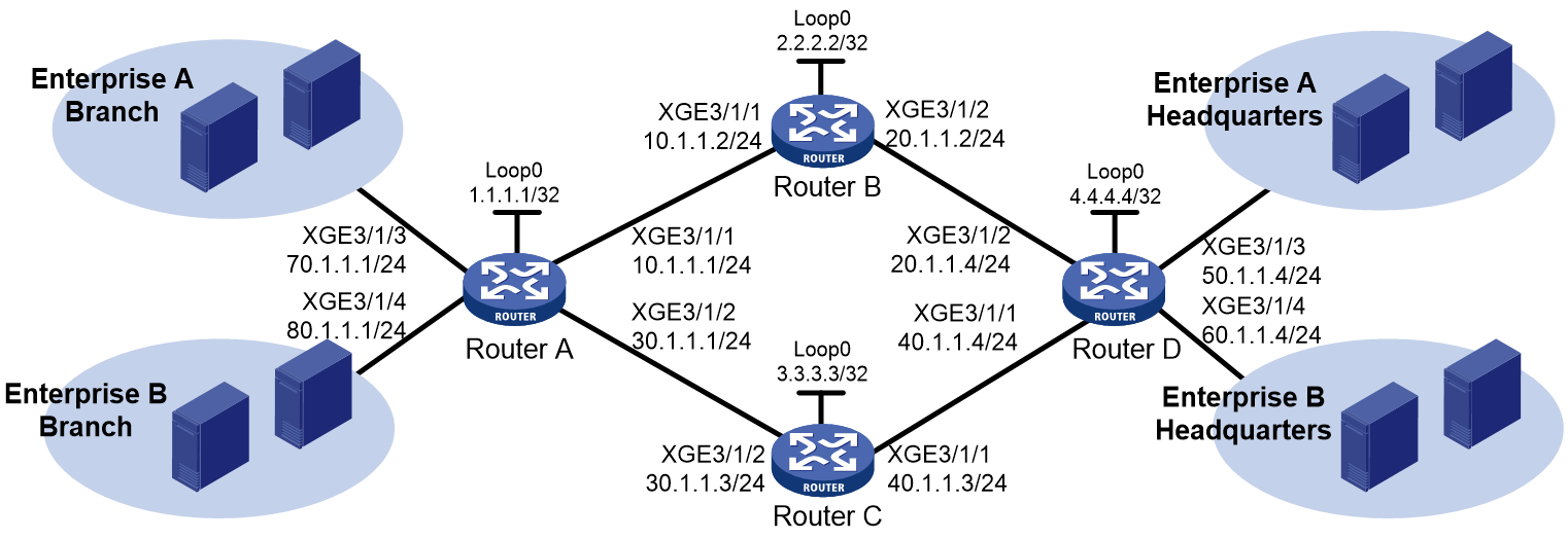
As shown in Figure 1, use RSVP-TE to establish two MPLS TE tunnels between Router A and Router D. The MPLS TE tunnel for Enterprise A requires a bandwidth of 20000 kbps. The MPLS TE tunnel for Enterprise B requires a bandwidth of 30000 kbps.
The maximum bandwidth of the link that each tunnel traverses is 50000 kbps. The maximum reservable bandwidth of each link is 40000 kbps.
Analysis
To establish MPLS TE tunnels through RSVP-TE, you must perform the following tasks:
· Enable MPLS, MPLS TE, and RSVP-TE on each interface that the MPLS TE tunnels traverse.
· On each interface that the MPLS TE tunnels traverse, configure link TE attributes, including the maximum link bandwidth and maximum reservable bandwidth.
· On each node that the MPLS TE tunnels traverse, configure the IGP TE extension to advertise the link TE attributes, which generates a TEDB on each node.
Based on the TEDB, CSPF calculates the shortest, TE constraints-compliant path to the tunnel destination. If you do not configure the IGP TE extension, the path is created based on IGP routing. The supported IGP TE extensions are OSPF TE and ISIS TE. This example uses OSPF TE.
· Create a tunnel interface on the ingress node of each MPLS TE tunnel, and perform the following tasks on the tunnel interface:
¡ Specify the tunnel destination address.
¡ Specify the tunnel bandwidth as required (20000 kbps for Enterprise A and 30000 kbps for Enterprise B).
¡ Specify the MPLS TE signaling protocol as RSVP-TE.
RSVP-TE advertises labels to establish CRLSPs and reserves bandwidth resources on each node along the calculated path.
· On the ingress node of each MPLS TE tunnel, configure static routing to direct traffic to the MPLS TE tunnel.
Restrictions and guidelines
Before configuration, disable the spanning tree feature globally or map each VLAN to an MSTI.
Procedures
1. Configure IP addresses for interfaces:
Configure IP addresses and masks for interfaces on Router A, including the loopback interface, as shown in Figure 1. (Details not shown.)
2. Configure OSPF to ensure IP connectivity among the routers:
# Configure Router A.
<RouterA> System-view
[RouterA] ospf
[RouterA-ospf-1] area 0
[RouterA-ospf-1-area-0.0.0.0] network 1.1.1.1 0.0.0.0
[RouterA-ospf-1-area-0.0.0.0] network 10.1.1.0 0.0.0.255
[RouterA-ospf-1-area-0.0.0.0] network 30.1.1.0 0.0.0.255
[RouterA-ospf-1-area-0.0.0.0] quit
[RouterA-ospf-1] quit
# Configure Router B.
<RouterB> System-view
[RouterB] ospf
[RouterB-ospf-1] area 0
[RouterB-ospf-1-area-0.0.0.0] network 2.2.2.2 0.0.0.0
[RouterB-ospf-1-area-0.0.0.0] network 10.1.1.0 0.0.0.255
[RouterB-ospf-1-area-0.0.0.0] network 20.1.1.0 0.0.0.255
[RouterB-ospf-1-area-0.0.0.0] quit
[RouterB-ospf-1] quit
# Configure Router C.
<RouterC> System-view
[RouterC] ospf
[RouterC-ospf-1] area 0
[RouterC-ospf-1-area-0.0.0.0] network 3.3.3.3 0.0.0.0
[RouterC-ospf-1-area-0.0.0.0] network 30.1.1.0 0.0.0.255
[RouterC-ospf-1-area-0.0.0.0] network 40.1.1.0 0.0.0.255
[RouterC-ospf-1-area-0.0.0.0] quit
[RouterC-ospf-1] quit
# Configure Router D.
<RouterD> System-view
[RouterD] ospf
[RouterD-ospf-1] area 0
[RouterD-ospf-1-area-0.0.0.0] network 4.4.4.4 0.0.0.0
[RouterD-ospf-1-area-0.0.0.0] network 20.1.1.0 0.0.0.255
[RouterD-ospf-1-area-0.0.0.0] network 40.1.1.0 0.0.0.255
[RouterD-ospf-1-area-0.0.0.0] quit
[RouterD-ospf-1] quit
# Execute the display ip routing-table command on each router to verify that the routers have learned the routes to one another, including the routes to the loopback interfaces. The following shows the output on Router A.
[RouterA] display ip routing-table
Destinations : 21 Routes : 21
Destination/Mask Proto Pre Cost NextHop Interface
0.0.0.0/32 Direct 0 0 127.0.0.1 InLoop0
1.1.1.1/32 Direct 0 0 127.0.0.1 InLoop0
2.2.2.2/32 O_INTRA 10 1 10.1.1.2 XGE3/1/1
3.3.3.3/32 O_INTRA 10 1 30.1.1.3 XGE3/1/2
4.4.4.4/32 O_INTRA 10 2 10.1.1.2 XGE3/1/1
10.1.1.0/24 Direct 0 0 10.1.1.1 XGE3/1/1
10.1.1.0/32 Direct 0 0 10.1.1.1 XGE3/1/1
10.1.1.1/32 Direct 0 0 127.0.0.1 InLoop0
10.1.1.255/32 Direct 0 0 10.1.1.1 XGE3/1/1
20.1.1.0/24 O_INTRA 10 2 10.1.1.2 XGE3/1/1
30.1.1.0/24 Direct 0 0 30.1.1.1 XGE3/1/2
30.1.1.0/32 Direct 0 0 30.1.1.1 XGE3/1/2
30.1.1.1/32 Direct 0 0 127.0.0.1 InLoop0
30.1.1.255/32 Direct 0 0 30.1.1.1 XGE3/1/2
127.0.0.0/8 Direct 0 0 127.0.0.1 InLoop0
127.0.0.0/32 Direct 0 0 127.0.0.1 InLoop0
127.0.0.1/32 Direct 0 0 127.0.0.1 InLoop0
127.255.255.255/32 Direct 0 0 127.0.0.1 InLoop0
224.0.0.0/4 Direct 0 0 0.0.0.0 NULL0
224.0.0.0/24 Direct 0 0 0.0.0.0 NULL0
255.255.255.255/32 Direct 0 0 127.0.0.1 InLoop0
3. Configure an LSR ID, and enable MPLS, MPLS TE, and RSVP-TE:
# Configure Router A.
[RouterA] mpls lsr-id 1.1.1.1
[RouterA] mpls te
[RouterA-te] quit
[RouterA] rsvp
[RouterA-rsvp] quit
[RouterA] interface ten-gigabitethernet 3/1/1
[RouterA-Ten-gigabitethernet3/1/1 mpls enable
[RouterA-Ten-gigabitethernet3/1/1] mpls te enable
[RouterA-Ten-gigabitethernet3/1/1] rsvp enable
[RouterA-Ten-gigabitethernet3/1/1] mpls te enable
[RouterA-Ten-gigabitethernet3/1/1] rsvp enable
[RouterA-Ten-gigabitethernet3/1/1] quit
[RouterA] interface Ten-gigabitethernet 3/1/2
[RouterA-Ten-gigabitethernet3/1/2] mpls enable
[RouterA-Ten-gigabitethernet3/1/2] mpls te enable
[RouterA-Ten-gigabitethernet3/1/2] rsvp enable
[RouterA-Ten-gigabitethernet3/1/2] quit
# Configure Router B.
[RouterB] mpls lsr-id 2.2.2.2
[RouterB] mpls te
[RouterB-te] quit
[RouterB] rsvp
[RouterB-rsvp] quit
[RouterB] interface Ten-gigabitethernet 3/1/1
[RouterB-Ten-gigabitethernet3/1/1] mpls enable
[RouterB-Ten-gigabitethernet3/1/1] mpls te enable
[RouterB-Ten-gigabitethernet3/1/1] rsvp enable
[RouterB-Ten-gigabitethernet3/1/1] quit
[RouterB] interface Ten-gigabitethernet 3/1/2
[RouterB-Ten-gigabitethernet3/1/2] mpls enable
[RouterB-Ten-gigabitethernet3/1/2] mpls te enable
[RouterB-Ten-gigabitethernet3/1/2] rsvp enable
[RouterB-Ten-gigabitethernet3/1/2] quit
# Configure Router C.
[RouterC] mpls lsr-id 3.3.3.3
[RouterC] mpls te
[RouterC-te] quit
[RouterC] rsvp
[RouterC-rsvp] quit
[RouterC] interface Ten-gigabitethernet 3/1/1
[RouterC-Ten-gigabitethernet3/1/1] mpls enable
[RouterC-Ten-gigabitethernet3/1/1 mpls te enable
[RouterC-Ten-gigabitethernet3/1/1] rsvp enable
[RouterC-Ten-gigabitethernet3/1/1] quit
[RouterC] interface Ten-gigabitethernet 3/1/2
[RouterC-Ten-gigabitethernet3/1/2] mpls enable
[RouterC-Ten-gigabitethernet3/1/2] mpls te enable
[RouterC-Ten-gigabitethernet3/1/2 rsvp enable
[RouterC-Ten-gigabitethernet3/1/2] quit
# Configure Router D.
[RouterD] mpls lsr-id 4.4.4.4
[RouterD] mpls te
[RouterD-te] quit
[RouterD] rsvp
[RouterD-rsvp] quit
[RouterD] interface Ten-gigabitethernet 3/1/1
[RouterD-Ten-gigabitethernet3/1/1] mpls enable
[RouterD-Ten-gigabitethernet3/1/1] mpls te enable
[RouterD-Ten-gigabitethernet3/1/1] rsvp enable
[RouterD-Ten-gigabitethernet3/1/1] quit
[RouterD] interface Ten-gigabitethernet 3/1/2
[RouterD-Ten-gigabitethernet3/1/2] mpls enable
[RouterD-Ten-gigabitethernet3/1/2] mpls te enable
[RouterD-Ten-gigabitethernet3/1/2] rsvp enable
[RouterD-Ten-gigabitethernet3/1/2] quit
4. Configure MPLS TE attributes of links:
# Configure the maximum link bandwidth and maximum reservable bandwidth on Router A.
[RouterA] interface Ten-gigabitethernet 3/1/1
[RouterA-Ten-gigabitethernet3/1/1] mpls te max-link-bandwidth 50000
[RouterA-Ten-gigabitethernet3/1/1] mpls te max-reservable-bandwidth 40000
[RouterA-Ten-gigabitethernet3/1/1] quit
[RouterA] interface Ten-gigabitethernet 3/1/2
[RouterA-Ten-gigabitethernet3/1/2] mpls te max-link-bandwidth 50000
[RouterA-Ten-gigabitethernet3/1/2] mpls te max-reservable-bandwidth 40000
[RouterA-Ten-gigabitethernet3/1/2] quit
# Configure the maximum link bandwidth and maximum reservable bandwidth on Router B.
[RouterB] interface Ten-gigabitethernett 3/1/1
[RouterB-Ten-gigabitethernet3/1/1] mpls te max-link-bandwidth 50000
[RouterB-Ten-gigabitethernet3/1/1 mpls te max-reservable-bandwidth 40000
[RouterB-Ten-gigabitethernet3/1/1] quit
[RouterB] interface Ten-gigabitethernet 3/1/2
[RouterB-Ten-gigabitethernet3/1/2] mpls te max-link-bandwidth 50000
[RouterB-Ten-gigabitethernet3/1/2] mpls te max-reservable-bandwidth 40000
[RouterB-Ten-gigabitethernet3/1/2 quit
# Configure the maximum link bandwidth and maximum reservable bandwidth on Router C.
[RouterC] interface Ten-gigabitethernet 3/1/1
[RouterC-Ten-gigabitethernet3/1/1] mpls te max-link-bandwidth 50000
[RouterC-Ten-gigabitethernet3/1/1] mpls te max-reservable-bandwidth 40000
[RouterC-Ten-gigabitethernet3/1/1] quit
[RouterC] interface Ten-gigabitethernet 3/1/2
[RouterC-Ten-gigabitethernet3/1/2] mpls te max-link-bandwidth 50000
[RouterC-Ten-gigabitethernet3/1/2] mpls te max-reservable-bandwidth 40000
[RouterC-Ten-gigabitethernet3/1/2] quit
# Configure the maximum link bandwidth and maximum reservable bandwidth on Router D.
[RouterD] interface Ten-gigabitethernet 3/1/1
[RouterD-Ten-gigabitethernet3/1/1] mpls te max-link-bandwidth 50000
[RouterD-Ten-gigabitethernet3/1/1] mpls te max-reservable-bandwidth 40000
[RouterD-Ten-gigabitethernet3/1/1] quit
[RouterD] interface Ten-gigabitethernet 3/1/2
[RouterD-Ten-gigabitethernet3/1/2] mpls te max-link-bandwidth 50000
[RouterD-Ten-gigabitethernet3/1/2] mpls te max-reservable-bandwidth 40000
[RouterD-Ten-gigabitethernet3/1/2] quit
5. Configure OSPF TE to advertise link TE attributes:
# Enable opaque LSA advertisement and reception on Router A. By default, the opaque LSA advertisement and reception capability is enabled.
[RouterA] ospf
[RouterA-ospf-1] opaque-capability enable
# Enable MPLS TE for OSPF area 0 on Router A.
[RouterA-ospf-1] area 0
[RouterA-ospf-1-area-0.0.0.0] mpls te enable
[RouterA-ospf-1-area-0.0.0.0] quit
[RouterA-ospf-1] quit
# Enable opaque LSA advertisement and reception on Router B. By default, the opaque LSA advertisement and reception capability is enabled.
[RouterB] ospf
[RouterB-ospf-1] opaque-capability enable
# Enable MPLS TE for OSPF area 0 on Router B.
[RouterB-ospf-1] area 0
[RouterB-ospf-1-area-0.0.0.0] mpls te enable
[RouterB-ospf-1-area-0.0.0.0] quit
[RouterB-ospf-1] quit
# Enable opaque LSA advertisement and reception on Router C. By default, the opaque LSA advertisement and reception capability is enabled.
[RouterC] ospf
[RouterC-ospf-1] opaque-capability enable
# Enable MPLS TE for OSPF area 0 on Router C.
[RouterC-ospf-1] area 0
[RouterC-ospf-1-area-0.0.0.0] mpls te enable
[RouterC-ospf-1-area-0.0.0.0] quit
[RouterC-ospf-1] quit
# Enable opaque LSA advertisement and reception on Router D. By default, the opaque LSA advertisement and reception capability is enabled.
[RouterD] ospf
[RouterD-ospf-1] opaque-capability enable
# Enable MPLS TE for OSPF area 0 on Router D.
[RouterD-ospf-1] area 0
[RouterD-ospf-1-area-0.0.0.0] mpls te enable
[RouterD-ospf-1-area-0.0.0.0] quit
[RouterD-ospf-1] quit
6. Configure MPLS TE tunnels on Router A:
# Configure MPLS TE tunnel interface Tunnel 1 to forward traffic of Enterprise A.
[RouterA] interface tunnel 1 mode mpls-te
[RouterA-Tunnel1] ip address 7.1.1.1 255.255.255.0
# Specify the tunnel destination address as the LSR ID of Router D, use RSVP-TE to establish the tunnel, and assign 20000 kbps bandwidth to the tunnel.
[RouterA-Tunnel1] destination 4.4.4.4
[RouterA-Tunnel1] mpls te signaling rsvp-te
[RouterA-Tunnel1] mpls te bandwidth 20000
# Enable route recording for MPLS TE tunnel 1.
[RouterA-Tunnel1] mpls te record-route
[RouterA-Tunnel1] quit
# Configure MPLS TE tunnel interface Tunnel 2 to forward traffic of Enterprise B.
[RouterA] interface tunnel 2 mode mpls-te
[RouterA-Tunnel2] ip address 8.1.1.1 255.255.255.0
# Specify the tunnel destination address as the LSR ID of Router D, use RSVP-TE to establish the tunnel, and assign 30000 kbps bandwidth to the tunnel.
[RouterA-Tunnel2] destination 4.4.4.4
[RouterA-Tunnel2] mpls te signaling rsvp-te
[RouterA-Tunnel2] mpls te bandwidth 30000
# Enable route recording for MPLS TE tunnel 2.
[RouterA-Tunnel2] mpls te record-route
[RouterA-Tunnel2] quit
7. Configure static routing on Router A to direct traffic to the MPLS TE tunnels:
# Configure a static route to direct traffic destined for 50.1.1.0/24 to MPLS TE tunnel interface Tunnel 1.
[RouterA] ip route-static 50.1.1.0 24 tunnel 1 preference 1
# Configure a static route to direct traffic destined for 60.1.1.0/24 to MPLS TE tunnel interface Tunnel 2.
[RouterA] ip route-static 60.1.1.0 24 tunnel 2 preference 1
Verifying the configuration
# Execute the display interface tunnel command on Router A. The output shows that the two tunnel interfaces are up.
[RouterA] display interface tunnel
Tunnel1
Current state: UP
Line protocol state: UP
Description: Tunnel1 Interface
Bandwidth: 64kbps
Maximum Transmit Unit: 64000
Internet Address is 7.1.1.1/24 (primary)
Tunnel source unknown, destination 4.4.4.4
Tunnel TTL 255
Tunnel protocol/transport CR_LSP
Last clearing of counters: Never
Last 300 seconds input rate: 0 bytes/sec, 0 bits/sec, 0 packets/sec
Last 300 seconds output rate: 0 bytes/sec, 0 bits/sec, 0 packets/sec
Input: 0 packets, 0 bytes, 0 drops
Output: 0 packets, 0 bytes, 0 drops
Tunnel2
Current state: UP
Line protocol state: UP
Description: Tunnel2 Interface
Bandwidth: 64kbps
Maximum Transmit Unit: 64000
Internet Address is 8.1.1.1/24 (primary)
Tunnel source unknown, destination 4.4.4.4
Tunnel TTL 255
Tunnel protocol/transport CR_LSP
Last clearing of counters: Never
Last 300 seconds input rate: 0 bytes/sec, 0 bits/sec, 0 packets/sec
Last 300 seconds output rate: 0 bytes/sec, 0 bits/sec, 0 packets/sec
Input: 0 packets, 0 bytes, 0 drops
Output: 0 packets, 0 bytes, 0 drops
# Execute the display mpls te tunnel-interface command on Router A to display detailed information about the MPLS TE tunnels.
[RouterA] display mpls te tunnel-interface
Tunnel Name : Tunnel 1
Tunnel State : Up (Main CRLSP up, Shared-resource CRLSP down)
Tunnel Attributes :
LSP ID :46362 Tunnel ID : 1
Admin State : Normal
Ingress LSR ID : 1.1.1.1 Egress LSR ID : 4.4.4.4
Signaling : RSVP-TE Static CRLSP Name : -
Resv Style : SE
Tunnel mode : -
Reverse-LSP name : -
Reverse-LSP LSR ID : - Reverse-LSP Tunnel ID: -
Class Type : CT0 Tunnel Bandwidth : 20000 kbps
Reserved Bandwidth : 20000 kbps
Setup Priority : 7 Holding Priority : 7
Affinity Attr/Mask : 0/0
Explicit Path : -
Backup Explicit Path : -
Metric Type : TE
Record Route : Enabled Record Label : Disabled
FRR Flag : Disabled Bandwidth Protection : Disabled
Backup Bandwidth Flag: Disabled Backup Bandwidth Type: -
Backup Bandwidth : -
Bypass Tunnel : No Auto Created : No
Route Pinning : Disabled
Retry Limit : 3 Retry Interval : 2 sec
Reoptimization : Disabled Reoptimization Freq : -
Backup Type : None Backup LSP ID : -
Auto Bandwidth : Disabled Auto Bandwidth Freq : -
Min Bandwidth : - Max Bandwidth : -
Collected Bandwidth : - Service-Class : -
Traffic Policy : Disable
Last Down Reason : Admin Down
Down Time : 2017-12-05 11:23:35:535
Tunnel Name : Tunnel 2
Tunnel State : Up (Main CRLSP up, Shared-resource CRLSP down)
Tunnel Attributes :
LSP ID : 46362 Tunnel ID : 2
Admin State : Normal
Ingress LSR ID : 1.1.1.1 Egress LSR ID : 4.4.4.4
Signaling : RSVP-TE Static CRLSP Name : -
Resv Style : SE
Tunnel mode : -
Reverse-LSP name : -
Reverse-LSP LSR ID : - Reverse-LSP Tunnel ID: -
Class Type : CT0 Tunnel Bandwidth : 30000 kbps
Reserved Bandwidth : 30000 kbps
Setup Priority : 7 Holding Priority : 7
Affinity Attr/Mask : 0/0
Explicit Path : -
Backup Explicit Path : -
Metric Type : TE
Record Route : Enabled Record Label : Disabled
FRR Flag : Disabled Bandwidth Protection : Disabled
Backup Bandwidth Flag: Disabled Backup Bandwidth Type: -
Backup Bandwidth : -
Bypass Tunnel : No Auto Created : No
Route Pinning : Disabled
Retry Limit : 3 Retry Interval : 2 sec
Reoptimization : Disabled Reoptimization Freq : -
Backup Type : None Backup LSP ID : -
Auto Bandwidth : Disabled Auto Bandwidth Freq : -
Min Bandwidth : - Max Bandwidth : -
Collected Bandwidth : - Service-Class : -
Traffic Policy : Disable
Last Down Reason : Admin Down
Down Time : 2017-12-05 11:23:35:535
# Execute the display ip routing-table command on Router A. The output shows two static route entries with output interfaces of Tunnel 1 and Tunnel 2.
[RouterA] display ip routing-table
Destinations : 30 Routes : 30
Destination/Mask Proto Pre Cost NextHop Interface
0.0.0.0/32 Direct 0 0 127.0.0.1 InLoop0
1.1.1.1/32 Direct 0 0 127.0.0.1 InLoop0
2.2.2.2/32 O_INTRA 10 1 10.1.1.2 XGE3/1/1
3.3.3.3/32 O_INTRA 10 1 30.1.1.3 XGE3/1/2
4.4.4.4/32 O_INTRA 10 2 10.1.1.2 XGE3/1/1
7.1.1.0/24 Direct 0 0 7.1.1.1 Tun1
7.1.1.0/32 Direct 0 0 7.1.1.1 Tun1
7.1.1.1/32 Direct 0 0 127.0.0.1 InLoop0
7.1.1.255/32 Direct 0 0 7.1.1.1 Tun1
8.1.1.0/24 Direct 0 0 8.1.1.1 Tun2
8.1.1.0/32 Direct 0 0 8.1.1.1 Tun2
8.1.1.1/32 Direct 0 0 127.0.0.1 InLoop0
8.1.1.255/32 Direct 0 0 8.1.1.1 Tun2
10.1.1.0/24 Direct 0 0 10.1.1.1 XGE3/1/1
10.1.1.0/32 Direct 0 0 10.1.1.1 XGE3/1/1
10.1.1.1/32 Direct 0 0 127.0.0.1 InLoop0
10.1.1.255/32 Direct 0 0 10.1.1.1 XGE3/1/1
50.1.1.0/24 Static 1 0 0.0.0.0 Tun1
30.1.1.0/24 Direct 0 0 30.1.1.1 XGE3/1/2
30.1.1.0/32 Direct 0 0 30.1.1.1 XGE3/1/2
30.1.1.1/32 Direct 0 0 127.0.0.1 InLoop0
30.1.1.255/32 Direct 0 0 30.1.1.1 XGE3/1/2
60.1.1.0/24 Static 1 0 0.0.0.0 Tun2
127.0.0.0/8 Direct 0 0 127.0.0.1 InLoop0
127.0.0.0/32 Direct 0 0 127.0.0.1 InLoop0
127.0.0.1/32 Direct 0 0 127.0.0.1 InLoop0
127.255.255.255/32 Direct 0 0 127.0.0.1 InLoop0
224.0.0.0/4 Direct 0 0 0.0.0.0 NULL0
224.0.0.0/24 Direct 0 0 0.0.0.0 NULL0
255.255.255.255/32 Direct 0 0 127.0.0.1 InLoop0
# Execute the display rsvp lsp verbose command on Router A to verify the following information:
· Tunnel 1 uses path Router A—Router B—Router D, and has a bandwidth of 20000 kbps.
· Tunnel 2 uses path Router A—Router C—Router D, and has a bandwidth of 30000 kbps.
[RouterA] display rsvp lsp verbose
Tunnel name: RouterA_t1
Destination: 4.4.4.4 Source: 1.1.1.1
Tunnel ID: 1 LSP ID: 46362
LSR type: Ingress Direction: Unidirectional
Setup priority: 7 Holding priority: 7
In-Label: - Out-Label: 1150
In-Interface: - Out-Interface: XGE3/1/1
Nexthop: 10.1.1.2 Exclude-any: 0
Include-Any: 0 Include-all: 0
Mean rate (CIR): 20000 kbps Mean burst size (CBS): 1000.00 bytes
Path MTU: 1500 Class type: CT0
RRO number: 6
10.1.1.1/32 Flag: 0x00 (No FRR)
10.1.1.2/32 Flag: 0x40 (No FRR/In-Int)
2.2.2.2/32 Flag: 0x20 (No FRR/Node-ID)
20.1.1.2/32 Flag: 0x00 (No FRR)
20.1.1.4/32 Flag: 0x40 (No FRR/In-Int)
4.4.4.4/32 Flag: 0x20 (No FRR/Node-ID)
Fast Reroute protection: None
Tunnel name: RouterA_t2
Destination: 4.4.4.4 Source: 1.1.1.1
Tunnel ID: 2 LSP ID: 46362
LSR type: Ingress Direction: Unidirectional
Setup priority: 7 Holding priority: 7
In-Label: - Out-Label: 1150
In-Interface: - Out-Interface: XGE3/1/2
Nexthop: 30.1.1.3 Exclude-any: 0
Include-Any: 0 Include-all: 0
Mean rate (CIR): 30000 kbps Mean burst size (CBS): 1000.00 bytes
Path MTU: 1500 Class type: CT0
RRO number: 6
30.1.1.1/32 Flag: 0x00 (No FRR)
30.1.1.3/32 Flag: 0x40 (No FRR/In-Int)
3.3.3.3/32 Flag: 0x20 (No FRR/Node-ID)
40.1.1.3/32 Flag: 0x00 (No FRR)
40.1.1.4/32 Flag: 0x40 (No FRR/In-Int)
4.4.4.4/32 Flag: 0x20 (No FRR/Node-ID)
Fast Reroute protection: None
Configuration files
· Router A:
#
ospf 1
area 0.0.0.0
network 1.1.1.1 0.0.0.0
network 10.1.1.0 0.0.0.255
network 30.1.1.0 0.0.0.255
mpls te enable
#
mpls lsr-id 1.1.1.1
#
mpls te
#
rsvp
#
interface Ten-GigabitEthernet3/1/1
port link-mode route
ip address 10.1.1.1 255.255.255.0
mpls enable
mpls te enable
mpls te max-link-bandwidth 50000
mpls te max-reservable-bandwidth 40000
rsvp enable
#
interface Ten-GigabitEthernet3/1/2
port link-mode route
ip address 30.1.1.1 255.255.255.0
mpls enable
mpls te enable
mpls te max-link-bandwidth 50000
mpls te max-reservable-bandwidth 40000
rsvp enable
#
interface Tunnel1 mode mpls-te
ip address 7.1.1.1 255.255.255.0
mpls te bandwidth ct0 20000
mpls te record-route
destination 4.4.4.4
#
interface Tunnel2 mode mpls-te
ip address 8.1.1.1 255.255.255.0
mpls te bandwidth ct0 30000
mpls te record-route
destination 4.4.4.4
#
ip route-static 50.1.1.0 24 Tunnel1 preference 1
ip route-static 60.1.1.0 24 Tunnel2 preference 1
#
· Router B:
#
ospf 1
area 0.0.0.0
network 2.2.2.2 0.0.0.0
network 10.1.1.0 0.0.0.255
network 20.1.1.0 0.0.0.255
mpls te enable
#
mpls lsr-id 2.2.2.2
#
mpls te
#
rsvp
#
interface LoopBack0
ip address 2.2.2.2 255.255.255.255
#
interface Ten-GigabitEthernet3/1/1
port link-mode route
ip address 10.1.1.2 255.255.255.0
mpls enable
mpls te enable
mpls te max-link-bandwidth 50000
mpls te max-reservable-bandwidth 40000
rsvp enable
#
interface Ten-GigabitEthernet3/1/2
port link-mode route
ip address 20.1.1.2 255.255.255.0
mpls enable
mpls te enable
mpls te max-link-bandwidth 50000
mpls te max-reservable-bandwidth 40000
rsvp enable
#
· Router C:
#
ospf 1
area 0.0.0.0
network 3.3.3.3 0.0.0.0
network 30.1.1.0 0.0.0.255
network 40.1.1.0 0.0.0.255
mpls te enable
#
mpls lsr-id 3.3.3.3
#
mpls te
#
rsvp
#
interface LoopBack0
ip address 3.3.3.3 255.255.255.0
#
interface Ten-GigabitEthernet3/1/1
port link-mode route
ip address 40.1.1.3 255.255.255.0
mpls enable
mpls te enable
mpls te max-link-bandwidth 50000
mpls te max-reservable-bandwidth 40000
rsvp enable
#
interface Ten-GigabitEthernet3/1/2
port link-mode route
ip address 30.1.1.3 255.255.255.0
mpls enable
mpls te enable
mpls te max-link-bandwidth 50000
mpls te max-reservable-bandwidth 40000
rsvp enable
#
· Router D:
#
ospf 1
area 0.0.0.0
network 4.4.4.4 0.0.0.0
network 20.1.1.0 0.0.0.255
network 40.1.1.0 0.0.0.255
mpls te enable
#
mpls lsr-id 4.4.4.4
#
mpls te
#
rsvp
#
interface LoopBack0
ip address 4.4.4.4 255.255.255.255
#
interface Ten-GigabitEthernet3/1/1
port link-mode route
ip address 40.1.1.4 255.255.255.0
mpls enable
mpls te enable
mpls te max-link-bandwidth 50000
mpls te max-reservable-bandwidth 40000
rsvp enable
#
interface Ten-GigabitEthernet3/1/2
port link-mode route
ip address 20.1.1.4 255.255.255.0
mpls enable
mpls te enable
mpls te max-link-bandwidth 50000
mpls te max-reservable-bandwidth 40000
rsvp enable
Example: Configuring MPLS TE FRR
Network configuration
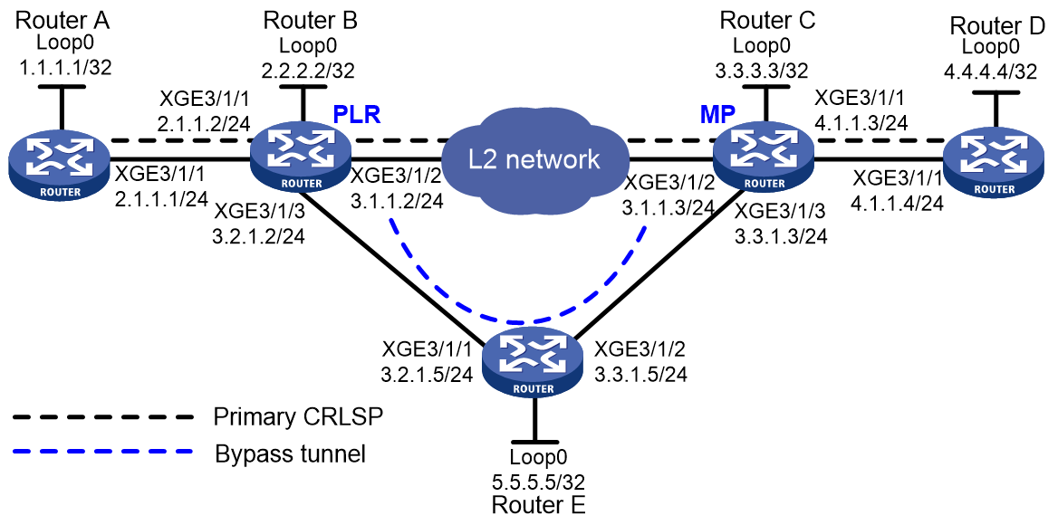
As shown in Figure 2, on the primary CRLSP Router A—Router B—Router C—Router D, configure MPLS TE FRR to protect the link Router B—Router C. When the link between Router B and Router C fails, MPLS TE can immediately switch traffic to the bypass tunnel Router B—Router E—Router C.
The primary CRLSP and the bypass tunnel each require a bandwidth of 30000 kbps. The maximum bandwidth of the link that each tunnel traverses is 50000 kbps. The maximum reservable bandwidth of each link is 40000 kbps.
Analysis
To implement MPLS TE FRR, you must perform the following tasks:
· Enable MPLS, MPLS TE, and RSVP-TE on each router for primary and bypass tunnel establishment.
· Configure explicit paths for the primary CRLSP and the bypass tunnel as required.
· Configure BFD for RSVP-TE on Router B and Router C for quick detection of the link failure.
BFD can immediately detect the failure of the protected link and notify RSVP-TE of the failure.
· Configure MPLS TE FRR on the ingress node of the primary CRLSP to ensure that traffic can be immediately switched to the bypass tunnel when BFD detects the failure of the protected link.
Restrictions and guidelines
When you configure MPLS TE FRR, follow these restrictions and guidelines:
· Only MPLS TE tunnels established through RSVP-TE support FRR.
· Do not configure both FRR and RSVP authentication on the same interface.
· Use bypass tunnels to protect only critical interfaces or links when bandwidth is insufficient. Bypass tunnels are pre-established and require extra bandwidth.
· Make sure the bandwidth assigned to the bypass tunnel is no less than the total bandwidth needed by all primary CRLSPs to be protected by the bypass tunnel. Otherwise, some primary CRLSPs might not be protected by the bypass tunnel.
· A bypass tunnel typically does not forward data when the primary CRLSP operates correctly. For a bypass tunnel to also forward data during tunnel protection, you must assign enough bandwidth to the bypass tunnel.
· A bypass tunnel cannot be used for services such as VPN.
· You cannot configure FRR for a bypass tunnel. A bypass tunnel cannot act as a primary CRLSP.
· Make sure the protected node or interface is not on the bypass tunnel.
· After an FRR, the primary CRLSP will be down if the FRR protection type (whether or not to provide bandwidth protection for the primary CRLSP) is changed.
Procedures
1. Configure IP addresses for interfaces:
Configure IP addresses and masks for interfaces on Router A, including the loopback interface, as shown in Figure 2. (Details not shown.)
2. Configure OSPF to ensure IP connectivity among the routers:
# Configure Router A.
<RouterA> System-view
[RouterA] ospf
[RouterA-ospf-1] area 0
[RouterA-ospf-1-area-0.0.0.0] network 1.1.1.1 0.0.0.0
[RouterA-ospf-1-area-0.0.0.0] network 2.1.1.0 0.0.0.255
[RouterA-ospf-1-area-0.0.0.0] quit
[RouterA-ospf-1] quit
# Configure Router B.
<RouterB> System-view
[RouterB] ospf
[RouterB-ospf-1] area 0
[RouterB-ospf-1-area-0.0.0.0] network 2.2.2.2 0.0.0.0
[RouterB-ospf-1-area-0.0.0.0] network 2.1.1.0 0.0.0.255
[RouterB-ospf-1-area-0.0.0.0] network 3.1.1.0 0.0.0.255
[RouterB-ospf-1-area-0.0.0.0] network 3.2.1.0 0.0.0.255
[RouterB-ospf-1-area-0.0.0.0] quit
[RouterB-ospf-1] quit
# Configure Router C.
<RouterC> System-view
[RouterC] ospf
[RouterC-ospf-1] area 0
[RouterC-ospf-1-area-0.0.0.0] network 3.3.3.3 0.0.0.0
[RouterC-ospf-1-area-0.0.0.0] network 3.1.1.0 0.0.0.255
[RouterC-ospf-1-area-0.0.0.0] network 3.3.1.0 0.0.0.255
[RouterC-ospf-1-area-0.0.0.0] network 4.1.1.0 0.0.0.255
[RouterC-ospf-1-area-0.0.0.0] quit
[RouterC-ospf-1] quit
# Configure Router D.
<RouterD> System-view
[RouterD] ospf
[RouterD-ospf-1] area 0
[RouterD-ospf-1-area-0.0.0.0] network 4.4.4.4 0.0.0.0
[RouterD-ospf-1-area-0.0.0.0] network 4.1.1.0 0.0.0.255
[RouterD-ospf-1-area-0.0.0.0] quit
[RouterD-ospf-1] quit
# Configure Router E.
<RouterE> System-view
[RouterE] ospf
[RouterE-ospf-1] area 0
[RouterE-ospf-1-area-0.0.0.0] network 5.5.5.5 0.0.0.0
[RouterE-ospf-1-area-0.0.0.0] network 3.2.1.0 0.0.0.255
[RouterE-ospf-1-area-0.0.0.0] network 3.3.1.0 0.0.0.255
[RouterE-ospf-1-area-0.0.0.0] quit
[RouterE-ospf-1] quit
# Execute the display ip routing-table command on each router to verify that the routers have learned the routes to one another, including the routes to the loopback interfaces. The following shows the output on Router A:
[RouterA] display ip routing-table
Destinations : 19 Routes : 19
Destination/Mask Proto Pre Cost NextHop Interface
0.0.0.0/32 Direct 0 0 127.0.0.1 InLoop0
1.1.1.1/32 Direct 0 0 127.0.0.1 InLoop0
2.1.1.0/24 Direct 0 0 2.1.1.1 XGE3/1/1
2.1.1.0/32 Direct 0 0 2.1.1.1 XGE3/1/1
2.1.1.1/32 Direct 0 0 127.0.0.1 InLoop0
2.1.1.255/32 Direct 0 0 2.1.1.1 XGE3/1/1
2.2.2.2/32 O_INTRA 10 1 2.1.1.2 XGE3/1/1
3.1.1.0/24 O_INTRA 10 2 2.1.1.2 XGE3/1/1
3.2.1.0/24 O_INTRA 10 2 2.1.1.2 XGE3/1/1
3.3.1.0/24 O_INTRA 10 3 2.1.1.2 XGE3/1/1
3.3.3.3/32 O_INTRA 10 2 2.1.1.2 XGE3/1/1
5.5.5.5/32 O_INTRA 10 2 2.1.1.2 XGE3/1/1
127.0.0.0/8 Direct 0 0 127.0.0.1 InLoop0
127.0.0.0/32 Direct 0 0 127.0.0.1 InLoop0
127.0.0.1/32 Direct 0 0 127.0.0.1 InLoop0
127.255.255.255/32 Direct 0 0 127.0.0.1 InLoop0
224.0.0.0/4 Direct 0 0 0.0.0.0 NULL0
224.0.0.0/24 Direct 0 0 0.0.0.0 NULL0
255.255.255.255/32 Direct 0 0 127.0.0.1 InLoop0
3. Configure an LSR ID, and enable MPLS, MPLS TE, and RSVP-TE on each router. Enable BFD for RSVP-TE on Router B and Router C:
# Configure Router A.
[RouterA] mpls lsr-id 1.1.1.1
[RouterA] mpls te
[RouterA-te] quit
[RouterA] rsvp
[RouterA-rsvp] quit
[RouterA] interface ten-gigabitethernet 3/1/1
[RouterA-Ten-gigabitethernet3/1/1] mpls enable
[RouterA-Ten-gigabitethernet3/1/1] mpls te enable
[RouterA-Ten-gigabitethernet3/1/1] rsvp enable
[RouterA-Ten-gigabitethernet3/1/1] quit
# Configure Router B.
[RouterB] mpls lsr-id 2.2.2.2
[RouterB] mpls te
[RouterB-te] quit
[RouterB] rsvp
[RouterB-rsvp] quit
[RouterB] interface ten-gigabitethernet 3/1/1
[RouterB-Ten-gigabitethernet3/1/1] mpls enable
[RouterB-Ten-gigabitethernet3/1/1] mpls te enable
[RouterB-Ten-gigabitethernet3/1/1] rsvp enable
[RouterB-Ten-gigabitethernet3/1/1] quit
[RouterB] interface ten-gigabitethernet 3/1/2
[RouterB-Ten-gigabitethernet3/1/2] mpls enable
[RouterB-Ten-gigabitethernet3/1/2] mpls te enable
[RouterB-Ten-gigabitethernet3/1/2] rsvp enable
[RouterB-Ten-gigabitethernet3/1/2] rsvp bfd enable
[RouterB-Ten-gigabitethernet3/1/2] quit
[RouterB] interface ten-gigabitethernet 3/1/3
[RouterB-Ten-gigabitethernet3/1/3] mpls enable
[RouterB-Ten-gigabitethernet3/1/3] mpls te enable
[RouterB-Ten-gigabitethernet3/1/3] rsvp enable
[RouterB-Ten-gigabitethernet3/1/3] quit
# Configure Router C.
[RouterC] mpls lsr-id 3.3.3.3
[RouterC] mpls te
[RouterC-te] quit
[RouterC] rsvp
[RouterC-rsvp] quit
[RouterC] interface ten-gigabitethernet 3/1/1
[RouterC-Ten-gigabitethernet3/1/1] mpls enable
[RouterC-Ten-gigabitethernet3/1/1] mpls te enable
[RouterC-Ten-gigabitethernet3/1/1] rsvp enable
[RouterC-Ten-gigabitethernet3/1/1] quit
[RouterC] interface ten-gigabitethernet 3/1/2
[RouterC-Ten-gigabitethernet3/1/2] mpls enable
[RouterC-Ten-gigabitethernet3/1/2] mpls te enable
[RouterC-Ten-gigabitethernet3/1/2] rsvp enable
[RouterC-Ten-gigabitethernet3/1/2] rsvp bfd enable
[RouterC-Ten-gigabitethernet3/1/2] quit
[RouterC] interface ten-gigabitethernet 3/1/3
[RouterC-Ten-gigabitethernet3/1/3] mpls enable
[RouterC-Ten-gigabitethernet3/1/3] mpls te enable
[RouterC-Ten-gigabitethernet3/1/3] rsvp enable
[RouterC-Ten-gigabitethernet3/1/3] quit
# Configure Router D.
[RouterD] mpls lsr-id 4.4.4.4
[RouterD] mpls te
[RouterD-te] quit
[RouterD] rsvp
[RouterD-rsvp] quit
[RouterD] interface ten-gigabitethernet 3/1/1
[RouterD-Ten-gigabitethernet3/1/1] mpls enable
[RouterD-Ten-gigabitethernet3/1/1] mpls te enable
[RouterD-Ten-gigabitethernet3/1/1] rsvp enable
[RouterD-Ten-gigabitethernet3/1/1] quit
# Configure Router E.
[RouterE] mpls lsr-id 5.5.5.5
[RouterE] mpls te
[RouterE-te] quit
[RouterE] rsvp
[RouterE-rsvp] quit
[RouterE] interface ten-gigabitethernet 3/1/1
[RouterE-Ten-gigabitethernet3/1/1] mpls enable
[RouterE-Ten-gigabitethernet3/1/1] mpls te enable
[RouterE-Ten-gigabitethernet3/1/1] rsvp enable
[RouterE-Ten-gigabitethernet3/1/1] quit
[RouterE] interface ten-gigabitethernet 3/1/2
[RouterE-Ten-gigabitethernet3/1/2] mpls enable
[RouterE-Ten-gigabitethernet3/1/2] mpls te enable
[RouterE-Ten-gigabitethernet3/1/2] rsvp enable
[RouterE-Ten-gigabitethernet3/1/2] quit
4. Configure MPLS TE attributes of links:
# Configure the maximum link bandwidth on Router A.
[RouterA] interface ten-gigabitethernet 3/1/1
[RouterA-Ten-gigabitethernet3/1/1] mpls te max-link-bandwidth 50000
[RouterA-Ten-gigabitethernet3/1/1] mpls te max-reservable-bandwidth 40000
[RouterA-Ten-gigabitethernet3/1/1] quit
# Configure the maximum link bandwidth on Router B.
[RouterB] interface ten-gigabitethernet 3/1/1
[RouterB-Ten-gigabitethernet3/1/1] mpls te max-link-bandwidth 50000
[RouterB-Ten-gigabitethernet3/1/1] mpls te max-reservable-bandwidth 40000
[RouterB-Ten-gigabitethernet3/1/1] quit
[RouterB] interface ten-gigabitethernet 3/1/2
[RouterB-Ten-gigabitethernet3/1/2] mpls te max-link-bandwidth 50000
[RouterB-Ten-gigabitethernet3/1/2] mpls te max-reservable-bandwidth 40000
[RouterB-Ten-gigabitethernet3/1/2] quit
[RouterB] interface ten-gigabitethernet 3/1/3
[RouterB-Ten-gigabitethernet3/1/3] mpls te max-link-bandwidth 50000
[RouterB-Ten-gigabitethernet3/1/3] mpls te max-reservable-bandwidth 40000
[RouterB-Ten-gigabitethernet3/1/3] quit
# Configure the maximum link bandwidth on Router C.
[RouterC] interface ten-gigabitethernet 3/1/1
[RouterC-Ten-gigabitethernet3/1/1] mpls te max-link-bandwidth 50000
[RouterC-Ten-gigabitethernet3/1/1] mpls te max-reservable-bandwidth 40000
[RouterC-Ten-gigabitethernet3/1/1] quit
[RouterC] interface ten-gigabitethernet 3/1/2
[RouterC-Ten-gigabitethernet3/1/2] mpls te max-link-bandwidth 50000
[RouterC-Ten-gigabitethernet3/1/2] mpls te max-reservable-bandwidth 40000
[RouterC-Ten-gigabitethernet3/1/2] quit
[RouterC] interface ten-gigabitethernet 3/1/3
[RouterC-Ten-gigabitethernet3/1/3] mpls te max-link-bandwidth 50000
[RouterC-Ten-gigabitethernet3/1/3] mpls te max-reservable-bandwidth 40000
[RouterC-Ten-gigabitethernet3/1/3] quit
# Configure the maximum link bandwidth on Router D.
[RouterD] interface ten-gigabitethernet 3/1/1
[RouterD-Ten-gigabitethernet3/1/1] mpls te max-link-bandwidth 50000
[RouterD-Ten-gigabitethernet3/1/1] mpls te max-reservable-bandwidth 40000
[RouterD-Ten-gigabitethernet3/1/1] quit
# Configure the maximum link bandwidth on Router E.
[RouterE] interface ten-gigabitethernet 3/1/1
[RouterE-Ten-gigabitethernet3/1/1] mpls te max-link-bandwidth 50000
[RouterE-Ten-gigabitethernet3/1/1] mpls te max-reservable-bandwidth 40000
[RouterE-Ten-gigabitethernet3/1/1] quit
[RouterE] interface ten-gigabitethernet 3/1/2
[RouterE-Ten-gigabitethernet3/1/2] mpls te max-link-bandwidth 50000
[RouterE-Ten-gigabitethernet3/1/2] mpls te max-reservable-bandwidth 40000
[RouterE-Ten-gigabitethernet3/1/2] quit
5. Configure OSPF TE to advertise link TE attributes:
# Enable opaque LSA advertisement and reception on Router A. By default, the opaque LSA advertisement and reception capability is enabled.
[RouterA] ospf
[RouterA-ospf-1] opaque-capability enable
# Enable MPLS TE for OSPF area 0 on Router A.
[RouterA-ospf-1] area 0
[RouterA-ospf-1-area-0.0.0.0] mpls te enable
[RouterA-ospf-1-area-0.0.0.0] quit
[RouterA-ospf-1] quit
# Enable opaque LSA advertisement and reception on Router B. By default, the opaque LSA advertisement and reception capability is enabled.
[RouterB] ospf
[RouterB-ospf-1] opaque-capability enable
# Enable MPLS TE for OSPF area 0 on Router B.
[RouterB-ospf-1] area 0
[RouterB-ospf-1-area-0.0.0.0] mpls te enable
[RouterB-ospf-1-area-0.0.0.0] quit
[RouterB-ospf-1] quit
# Enable opaque LSA advertisement and reception on Router C. By default, the opaque LSA advertisement and reception capability is enabled.
[RouterC] ospf
[RouterC-ospf-1] opaque-capability enable
# Enable MPLS TE for OSPF area 0 on Router C.
[RouterC-ospf-1] area 0
[RouterC-ospf-1-area-0.0.0.0] mpls te enable
[RouterC-ospf-1-area-0.0.0.0] quit
[RouterC-ospf-1] quit
# Enable opaque LSA advertisement and reception on Router D. By default, the opaque LSA advertisement and reception capability is enabled.
[RouterD] ospf
[RouterD-ospf-1] opaque-capability enable
# Enable MPLS TE for OSPF area 0 on Router D.
[RouterD-ospf-1] area 0
[RouterD-ospf-1-area-0.0.0.0] mpls te enable
[RouterD-ospf-1-area-0.0.0.0] quit
[RouterD-ospf-1] quit
# Enable opaque LSA advertisement and reception on Router E. By default, the opaque LSA advertisement and reception capability is enabled.
[RouterE] ospf
[RouterE-ospf-1] opaque-capability enable
# Enable MPLS TE for OSPF area 0 on Router E.
[RouterE-ospf-1] area 0
[RouterE-ospf-1-area-0.0.0.0] mpls te enable
[RouterE-ospf-1-area-0.0.0.0] quit
[RouterE-ospf-1] quit
6. Configure an MPLS TE tunnel on Router A (the ingress node of the primary CRLSP):
# Configure an explicit path named pri-path for the primary CRLSP.
[RouterA] explicit-path pri-path
[RouterA-explicit-path-pri-path] nexthop 2.1.1.2
[RouterA-explicit-path-pri-path] nexthop 3.1.1.3
[RouterA-explicit-path-pri-path] nexthop 4.1.1.4
[RouterA-explicit-path-pri-path] nexthop 4.4.4.4
[RouterA-explicit-path-pri-path] quit
# Configure MPLS TE tunnel interface Tunnel 4 for the primary CRLSP.
[RouterA] interface tunnel4 mode mpls-te
[RouterA-Tunnel4] ip address 10.1.1.1 255.255.255.0
# Specify the tunnel destination address as the LSR ID of Router D, configure MPLS TE to use RSVP-TE to establish the tunnel, and assign 30000 kbps bandwidth to the tunnel.
[RouterA-Tunnel4] destination 4.4.4.4
[RouterA-Tunnel4] mpls te signaling rsvp-te
[RouterA-Tunnel4] mpls te bandwidth 30000
# Specify the explicit path to be used as pri-path.
[RouterA-Tunnel4] mpls te path preference 1 explicit-path pri-path
# Enable FRR for the MPLS TE tunnel.
[RouterA-Tunnel4] mpls te fast-reroute
[RouterA-Tunnel4] quit
# Execute the display interface tunnel command on Router A. The output shows that tunnel interface Tunnel 4 is up.
[RouterA] display interface tunnel
Tunnel4
Current state: UP
Line protocol state: UP
Description: Tunnel4 Interface
Bandwidth: 64kbps
Maximum Transmit Unit: 64000
Internet Address is 10.1.1.1/24 (primary)
Tunnel source unknown, destination 4.4.4.4
Tunnel TTL 255
Tunnel protocol/transport CR_LSP
Last clearing of counters: Never
Last 300 seconds input rate: 0 bytes/sec, 0 bits/sec, 0 packets/sec
Last 300 seconds output rate: 0 bytes/sec, 0 bits/sec, 0 packets/sec
Input: 0 packets, 0 bytes, 0 drops
Output: 0 packets, 0 bytes, 0 drops
# Execute the display mpls te tunnel-interface command on Router A to display detailed information about the MPLS TE tunnel.
[RouterA] display mpls te tunnel-interface
Tunnel Name : Tunnel 4
Tunnel State : Up (Main CRLSP up, Shared-resource CRLSP down)
Tunnel Attributes :
LSP ID : 37325 Tunnel ID : 4
Admin State : Normal
Ingress LSR ID : 1.1.1.1 Egress LSR ID : 4.4.4.4
Signaling : RSVP-TE Static CRLSP Name : -
Resv Style : SE
Tunnel mode : -
Reverse-LSP name : -
Reverse-LSP LSR ID : - Reverse-LSP Tunnel ID: -
Class Type : CT0 Tunnel Bandwidth : 30000 kbps
Reserved Bandwidth : 30000 kbps
Setup Priority : 7 Holding Priority : 7
Affinity Attr/Mask : 0/0
Explicit Path : pri-path
Backup Explicit Path : -
Metric Type : TE
Record Route : Enabled Record Label : Enabled
FRR Flag : Enabled Bandwidth Protection : Disabled
Backup Bandwidth Flag: Disabled Backup Bandwidth Type: -
Backup Bandwidth : -
Bypass Tunnel : No Auto Created : No
Route Pinning : Disabled
Retry Limit : 3 Retry Interval : 2 sec
Reoptimization : Disabled Reoptimization Freq : -
Backup Type : None Backup LSP ID : -
Auto Bandwidth : Disabled Auto Bandwidth Freq : -
Min Bandwidth : - Max Bandwidth : -
Collected Bandwidth : - Service-Class : -
Traffic Policy : Disable
Last Down Reason : Admin Down
Down Time : 2017-12-05 11:23:35:535
7. Configure a bypass tunnel on Router B (the PLR):
# Configure an explicit path named by-path for the bypass tunnel.
[RouterB] explicit-path by-path
[RouterB-explicit-path-by-path] nexthop 3.2.1.5
[RouterB-explicit-path-by-path] nexthop 3.3.1.3
[RouterB-explicit-path-by-path] nexthop 3.3.3.3
[RouterB-explicit-path-by-path] quit
# Configure MPLS TE tunnel interface Tunnel 5 for the bypass tunnel.
[RouterB] interface tunnel 5 mode mpls-te
[RouterB-Tunnel5] ip address 11.1.1.1 255.255.255.0
# Specify the tunnel destination address as the LSR ID of Router C and configure MPLS TE to use RSVP-TE to establish the tunnel.
[RouterB-Tunnel5] destination 3.3.3.3
[RouterB-Tunnel5] mpls te signaling rsvp-te
# Set the bandwidth that the bypass tunnel can protect to 30000 kbps.
[RouterB-Tunnel5] mpls te backup bandwidth 30000
# Specify the explicit path to be used as by-path.
[RouterB-Tunnel5] mpls te path preference 1 explicit-path by-path
[RouterB-Tunnel5] quit
# Bind the bypass tunnel to the protected interface.
[RouterB] interface ten-gigabitethernet 3/1/2
[RouterB-Ten-gigabitethernet3/1/2] mpls te fast-reroute bypass-tunnel tunnel 5
[RouterB-Ten-gigabitethernet3/1/2] quit
# Execute the display interface tunnel command on Router B. The output shows that tunnel interface Tunnel 5 is up.
[RouterB] display interface tunnel
Tunnel5
Current state: UP
Line protocol state: DOWN
Description: Tunnel5 Interface
Bandwidth: 64kbps
Maximum Transmit Unit: 64000
Internet Address is 11.1.1.1/24 (primary)
Tunnel source unknown, destination 3.3.3.3
Tunnel TTL 255
Tunnel protocol/transport CR_LSP
Last clearing of counters: Never
Last 300 seconds input rate: 0 bytes/sec, 0 bits/sec, 0 packets/sec
Last 300 seconds output rate: 0 bytes/sec, 0 bits/sec, 0 packets/sec
Input: 0 packets, 0 bytes, 0 drops
Output: 0 packets, 0 bytes, 0 drops
8. Configure a static route on Router A to direct traffic destined for 4.1.1.0/24 to MPLS TE tunnel interface Tunnel 4.
[RouterA] ip route-static 4.1.1.0 24 tunnel 4 preference 1
Verifying the configuration
# Execute the display mpls lsp command on each Router. The output shows the LSP entries. Router B has two CRLSPs. The bypass tunnel backs up the primary CRLSP.
[RouterA] display mpls lsp
FEC Proto In/Out Label Interface/Out NHLFE
1.1.1.1/4/37325 RSVP -/1150 XGE3/1/1
2.1.1.2 Local -/- XGE3/1/1
Tunnel4 Local -/- NHLFE1026
[RouterB] display mpls lsp
FEC Proto In/Out Label Interface/Out NHLFE
1.1.1.1/4/37325 RSVP 1150/1147 XGE3/1/2
Backup 1150/1147 Tun5
2.2.2.2/5/18928 RSVP -/1149 XGE3/1/3
3.1.1.3 Local -/- XGE3/1/2
3.2.1.5 Local -/- XGE3/1/3
Tunnel5 Local -/- NHLFE1027
[RouterC] display mpls lsp
FEC Proto In/Out Label Interface/Out NHLFE
1.1.1.1/4/37325 RSVP 1147/3 XGE3/1/1
2.2.2.2/5/18928 RSVP 3/- -
4.1.1.4 Local -/- XGE3/1/1
# Shut down the protected interface Ten-GigabitEthernet 3/1/2 on the PLR (Router B).
[RouterB] interface ten-gigabitethernet 3/1/2
[RouterB-Ten-gigabitethernet3/1/2] shutdown
[RouterB-Ten-gigabitethernet3/1/2] quit
# Execute the display interface tunnel 4 command on Router A to display information about the primary CRLSP. The output shows that the tunnel interface is still up.
[RouterA] display interface tunnel 4
Tunnel4
Current state: UP
Line protocol state: UP
Description: Tunnel4 Interface
Bandwidth: 64kbps
Maximum Transmit Unit: 64000
Internet Address is 10.1.1.1/24 (primary)
Tunnel source unknown, destination 4.4.4.4
Tunnel TTL 255
Tunnel protocol/transport CR_LSP
Last clearing of counters: Never
Last 300 seconds input rate: 0 bytes/sec, 0 bits/sec, 0 packets/sec
Last 300 seconds output rate: 0 bytes/sec, 0 bits/sec, 0 packets/sec
Input: 0 packets, 0 bytes, 0 drops
Output: 0 packets, 0 bytes, 0 drops
# Execute the display mpls te tunnel-interface command on Router A to display detailed information about the tunnel interface.
[RouterA] display mpls te tunnel-interface
Tunnel Name : Tunnel 4
Tunnel State : Up (Main CRLSP up, Shared-resource CRLSP being set up)
Tunnel Attributes :
LSP ID : 37325 Tunnel ID : 4
Admin State : Normal
Ingress LSR ID : 1.1.1.1 Egress LSR ID : 4.4.4.4
Signaling : RSVP-TE Static CRLSP Name : -
Resv Style : SE
Tunnel mode : -
Reverse-LSP name : -
Reverse-LSP LSR ID : - Reverse-LSP Tunnel ID: -
Class Type : CT0 Tunnel Bandwidth : 30000 kbps
Reserved Bandwidth : 30000 kbps
Setup Priority : 7 Holding Priority : 7
Affinity Attr/Mask : 0/0
Explicit Path : pri-path
Backup Explicit Path : -
Metric Type : TE
Record Route : Enabled Record Label : Enabled
FRR Flag : Enabled Bandwidth Protection : Disabled
Backup Bandwidth Flag: Disabled Backup Bandwidth Type: -
Backup Bandwidth : -
Bypass Tunnel : No Auto Created : No
Route Pinning : Disabled
Retry Limit : 3 Retry Interval : 2 sec
Reoptimization : Disabled Reoptimization Freq : -
Backup Type : None Backup LSP ID : -
Auto Bandwidth : Disabled Auto Bandwidth Freq : -
Min Bandwidth : - Max Bandwidth : -
Collected Bandwidth : - Service-Class : -
Traffic Policy : Disable
Last Down Reason : Admin Down
Down Time : 2017-12-05 11:23:35:535
# Execute the display mpls lsp command on Router B. The output shows that the bypass tunnel is in use.
[RouterB] display mpls lsp
FEC Proto In/Out Label Interface/Out NHLFE
1.1.1.1/4/37325 RSVP 1150/1147 Tun5
2.2.2.2/5/18928 RSVP -/1149 XGE3/1/3
3.2.1.5 Local -/- XGE3/1/3
Tunnel5 Local -/- NHLFE1027
# On the PLR, configure the interval for selecting an optimal bypass tunnel as 5 seconds.
[RouterB] mpls te
[RouterB-te] fast-reroute timer 5
[RouterB-te] quit
# On the PLR, bring up the protected interface Ten-GigabitEthernet 3/1/2.
[RouterB] interface ten-gigabitethernet 3/1/2
[RouterB-Ten-gigabitethernet3/1/2] undo shutdown
[RouterB-Ten-gigabitethernet3/1/2 quit
# Execute the display interface tunnel 4 command on Router A to display information about the primary CRLSP. The output shows that the tunnel interface is in up state.
[RouterA] display interface tunnel 4
Tunnel4
Current state: UP
Line protocol state: UP
Description: Tunnel4 Interface
Bandwidth: 64kbps
Maximum Transmit Unit: 64000
Internet Address is 10.1.1.1/24 (primary)
Tunnel source unknown, destination 4.4.4.4
Tunnel TTL 255
Tunnel protocol/transport CR_LSP
Last clearing of counters: Never
Last 300 seconds input rate: 0 bytes/sec, 0 bits/sec, 0 packets/sec
Last 300 seconds output rate: 0 bytes/sec, 0 bits/sec, 0 packets/sec
Input: 0 packets, 0 bytes, 0 drops
Output: 0 packets, 0 bytes, 0 drops
# Wait for about 5 seconds, execute the display mpls lsp verbose command on Router B. The output shows that Tunnel 5 is bound to interface Ten-GigabitEthernet 3/1/2 but is not in use.
[RouterB] display mpls lsp verbose
Destination : 4.4.4.4
FEC : 1.1.1.1/4/53319
Protocol : RSVP
LSR Type : Transit
Service : -
In-Label : 1150
Path ID : 0x540000003.1
State : Active
Out-Label : 1150
Nexthop : 3.1.1.3
Out-Interface: XGE3/1/2
BkLabel : 1150
BkInterface : Tun5
Destination : 3.3.3.3
FEC : 2.2.2.2/5/16429
Protocol : RSVP
LSR Type : Ingress
Service : -
NHLFE ID : 1025
State : Active
Out-Label : 1151
Nexthop : 3.2.1.5
Out-Interface: XGE3/1/3
Destination : 3.1.1.3
FEC : 3.1.1.3
Protocol : Local
LSR Type : Ingress
Service : -
NHLFE ID : 1027
State : Active
Nexthop : 3.1.1.3
Out-Interface: XGE3/1/2
Destination : 3.2.1.5
FEC : 3.2.1.5
Protocol : Local
LSR Type : Ingress
Service : -
NHLFE ID : 1024
State : Active
Nexthop : 3.2.1.5
Out-Interface: XGE3/1/3
Destination : 3.3.3.3
FEC : Tunnel5
Protocol : Local
LSR Type : Ingress
Service : -
NHLFE ID : 268435461
State : Active
Out-Interface: NHLFE1025
# Execute the display ip routing-table command on Router A. The output shows a static route entry with interface Tunnel 4 as the output interface.
[RouterA] display ip routing-table
Destinations : 25 Routes : 25
Destination/Mask Proto Pre Cost NextHop Interface
0.0.0.0/32 Direct 0 0 127.0.0.1 InLoop0
1.1.1.1/32 Direct 0 0 127.0.0.1 InLoop0
2.1.1.0/24 Direct 0 0 2.1.1.1 XGE3/1/1
2.1.1.0/32 Direct 0 0 2.1.1.1 XGE3/1/1
2.1.1.1/32 Direct 0 0 127.0.0.1 InLoop0
2.1.1.255/32 Direct 0 0 2.1.1.1 XGE3/1/1
2.2.2.2/32 O_INTRA 10 1 2.1.1.2 XGE3/1/1
3.1.1.0/24 O_INTRA 10 2 2.1.1.2 XGE3/1/1
3.2.1.0/24 O_INTRA 10 2 2.1.1.2 XGE3/1/1
3.3.1.0/24 O_INTRA 10 3 2.1.1.2 XGE3/1/1
3.3.3.3/32 O_INTRA 10 2 2.1.1.2 XGE3/1/1
4.1.1.0/24 Static 1 0 0.0.0.0 Tun4
4.4.4.4/32 O_INTRA 10 3 2.1.1.2 XGE3/1/1
5.5.5.5/32 O_INTRA 10 2 2.1.1.2 XGE3/1/1
10.1.1.0/24 Direct 0 0 10.1.1.1 Tun4
10.1.1.0/32 Direct 0 0 10.1.1.1 Tun4
10.1.1.1/32 Direct 0 0 127.0.0.1 InLoop0
10.1.1.255/32 Direct 0 0 10.1.1.1 Tun4
127.0.0.0/8 Direct 0 0 127.0.0.1 InLoop0
127.0.0.0/32 Direct 0 0 127.0.0.1 InLoop0
127.0.0.1/32 Direct 0 0 127.0.0.1 InLoop0
127.255.255.255/32 Direct 0 0 127.0.0.1 InLoop0
224.0.0.0/4 Direct 0 0 0.0.0.0 NULL0
224.0.0.0/24 Direct 0 0 0.0.0.0 NULL0
255.255.255.255/32 Direct 0 0 127.0.0.1 InLoop0
Configuration files
· Router A
#
ospf 1
area 0.0.0.0
network 1.1.1.1 0.0.0.0
network 2.1.1.0 0.0.0.255
mpls te enable
#
mpls lsr-id 1.1.1.1
#
mpls te
#
explicit-path pri-path
nexthop index 1 2.1.1.2 include strict
nexthop index 101 3.1.1.3 include strict
nexthop index 201 4.1.1.4 include strict
nexthop index 301 4.4.4.4 include strict
#
rsvp
#
interface LoopBack0
ip address 1.1.1.1 255.255.255.255
#
interface Ten-GigabitEthernet3/1/1
port link-mode route
ip address 2.1.1.1 255.255.255.0
mpls enable
mpls te enable
mpls te max-link-bandwidth 50000
mpls te max-reservable-bandwidth 40000
rsvp enable
#
interface Tunnel4 mode mpls-te
ip address 10.1.1.1 255.255.255.0
mpls te bandwidth ct0 30000
mpls te path preference 1 explicit-path pri-path
mpls te fast-reroute
destination 4.4.4.4
#
ip route-static 4.1.1.0 24 Tunnel4 preference 1
#
· Router B
#
ospf 1
area 0.0.0.0
network 2.1.1.0 0.0.0.255
network 2.2.2.2 0.0.0.0
network 3.1.1.0 0.0.0.255
network 3.2.1.0 0.0.0.255
mpls te enable
#
mpls lsr-id 2.2.2.2
#
mpls te
fast-reroute timer 5
#
explicit-path by-path
nexthop index 1 3.2.1.5 include strict
nexthop index 101 3.3.1.3 include strict
nexthop index 201 3.3.3.3 include strict
#
rsvp
#
interface LoopBack0
ip address 2.2.2.2 255.255.255.255
#
interface Ten-GigabitEthernet3/1/1
port link-mode route
ip address 2.1.1.2 255.255.255.0
mpls enable
mpls te enable
mpls te max-link-bandwidth 50000
mpls te max-reservable-bandwidth 40000
rsvp enable
#
interface Ten-GigabitEthernet3/1/2
port link-mode route
ip address 3.1.1.2 255.255.255.0
mpls enable
mpls te enable
mpls te max-link-bandwidth 50000
mpls te max-reservable-bandwidth 40000
mpls te fast-reroute bypass-tunnel Tunnel5
rsvp enable
rsvp bfd enable
#
interface Ten-GigabitEthernet3/1/3
port link-mode route
ip address 3.2.1.2 255.255.255.0
mpls enable
mpls te enable
mpls te max-link-bandwidth 50000
mpls te max-reservable-bandwidth 40000
rsvp enable
#
interface Tunnel5 mode mpls-te
ip address 11.1.1.1 255.255.255.0
mpls te backup bandwidth ct0 30000
mpls te path preference 1 explicit-path by-path
destination 3.3.3.3
#
· Router C
#
ospf 1
area 0.0.0.0
network 3.1.1.0 0.0.0.255
network 3.3.1.0 0.0.0.255
network 3.3.3.3 0.0.0.0
network 4.1.1.0 0.0.0.255
mpls te enable
#
mpls lsr-id 3.3.3.3
#
mpls te
#
rsvp
#
interface LoopBack0
ip address 3.3.3.3 255.255.255.255
#
interface Ten-GigabitEthernet3/1/1
port link-mode route
ip address 4.1.1.3 255.255.255.0
mpls enable
mpls te enable
mpls te max-link-bandwidth 50000
mpls te max-reservable-bandwidth 40000
rsvp enable
#
interface Ten-GigabitEthernet3/1/2
port link-mode route
ip address 3.1.1.3 255.255.255.0
mpls enable
mpls te enable
mpls te max-link-bandwidth 50000
mpls te max-reservable-bandwidth 40000
rsvp enable
rsvp bfd enable
#
interface Ten-GigabitEthernet3/1/3
port link-mode route
ip address 3.3.1.3 255.255.255.0
mpls enable
mpls te enable
mpls te max-link-bandwidth 50000
mpls te max-reservable-bandwidth 40000
rsvp enable
#
· Router D
#
ospf 1
area 0.0.0.0
network 4.1.1.0 0.0.0.255
network 4.4.4.4 0.0.0.0
mpls te enable
#
mpls lsr-id 4.4.4.4
#
mpls te
#
rsvp
#
interface LoopBack0
ip address 4.4.4.4 255.255.255.255
#
interface Ten-GigabitEthernet3/1/1
port link-mode route
ip address 4.1.1.4 255.255.255.0
mpls enable
mpls te enable
mpls te max-link-bandwidth 50000
mpls te max-reservable-bandwidth 40000
rsvp enable
#
· Router E
#
ospf 1
area 0.0.0.0
network 3.2.1.0 0.0.0.255
network 3.3.1.0 0.0.0.255
network 5.5.5.5 0.0.0.0
mpls te enable
#
mpls lsr-id 5.5.5.5
#
mpls te
#
rsvp
#
interface LoopBack0
ip address 5.5.5.5 255.255.255.255
#
interface Ten-GigabitEthernet3/1/1
port link-mode route
ip address 3.2.1.5 255.255.255.0
mpls enable
mpls te enable
mpls te max-link-bandwidth 50000
mpls te max-reservable-bandwidth 40000
rsvp enable
#
interface Ten-GigabitEthernet3/1/2
port link-mode route
ip address 3.3.1.5 255.255.255.0
mpls enable
mpls te enable
mpls te max-link-bandwidth 50000
mpls te max-reservable-bandwidth 40000
rsvp enable
#
Related documentation
· H3C SR8800-X Routers MPLS Configuration Guide-R8380
· H3C SR8800-X Routers MPLS Command Reference-R8380
