- Table of Contents
-
- H3C CR16000-M Routers Installation Guide-5W101
- 00-Preface
- 01-Safety precautions
- 02-Preparing for installation
- 03-Installing the router
- 04-Installing removable components
- 05-Connecting cables
- 06-Verifying the installation
- 07-Starting and configuring the router
- 08-Replacement procedures
- 09-Troubleshooting
- 10-Appendix A Engineering labels
- 11-Appendix B Cable assembling and management
- 12-Appendix C Repackaging the Router
- Related Documents
-
| Title | Size | Download |
|---|---|---|
| 12-Appendix C Repackaging the Router | 696.08 KB |
12 Appendix C Repackaging the router
Removing cables from the router
Repackaging the router accessories
Removing cable management brackets
Repackaging the router chassis
Removing the chassis from the rack
Repackaging the router chassis
12 Appendix C Repackaging the router
This chapter describes how to repackage the router chassis, power module, card, and cable management bracket.
Removing cables from the router
Before repackaging the router, remove all cables such as the power cord, console cable, twisted pair, optical fiber, and grounding cable from the router.
Removing the power cord
1. Power off the server.
2. Switch off the circuit breakers at the input end of all power cords.
3. Wear an ESD wrist strap, and make sure it has a good skin contact and is correctly grounded.
For more information, see "Attaching an ESD wrist strap."
4. Remove the power cord:
¡ AC power cord—Remove the cable tie that secures the power cord, and then pull out the plug.
¡ DC power cord with a power plug—Remove the cable tie that secures the power cord, loosen the fastening screw on the power cord, and then pull out the plug.
¡ DC power cord with a ring terminal—Remove the cable tie that secures the power cord, remove the ring terminal protective cover and the fastening screw (rotate anticlockwise), and then disconnect the ring terminal from the power module.
Removing the console cable
1. Pull the RJ-45 connector of the console cable out from the console port of the router.
2. Pull the DB-9 connector of the console cable out from the serial port of the PC.
Removing the network cables
Remove the Ethernet twisted pair cables, fibers, and other cables from all the interfaces on the router.
|
|
NOTE: After pulling out an optical fiber from an optical transceiver module, cover the connector of the optical fiber with a dust cap to keep the connector clean. |
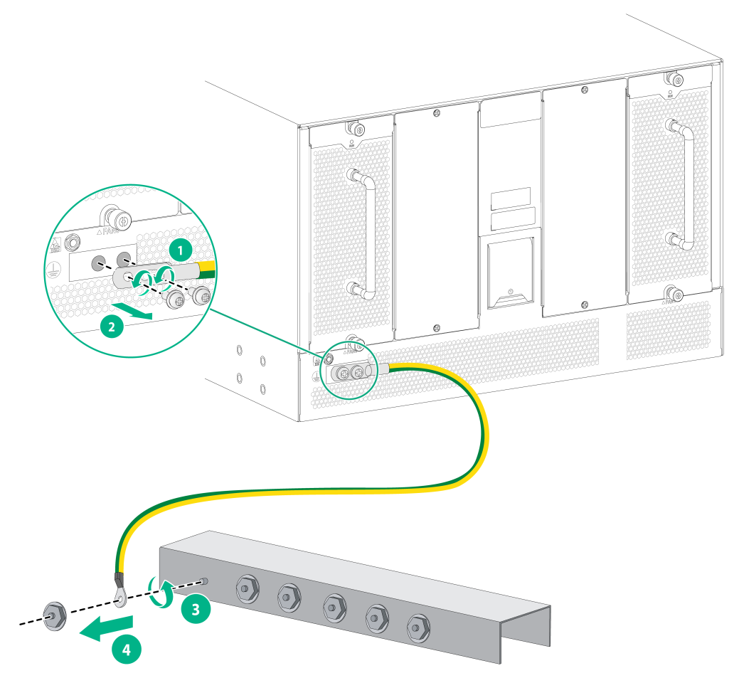
Removing the grounding cable
1. Remove the two screws at the grounding holes of the chassis, and then remove the grounding cable from the chassis, as shown by callouts 1 and 2.
2. Use a lever to loosen the hex nut on the grounding post of the grounding strip, and remove the other end of the grounding cable (with a ring terminal) from the grounding post, as shown by callouts 3 and 4.
Figure12-1 Removing the grounding cable
Repackaging the router accessories
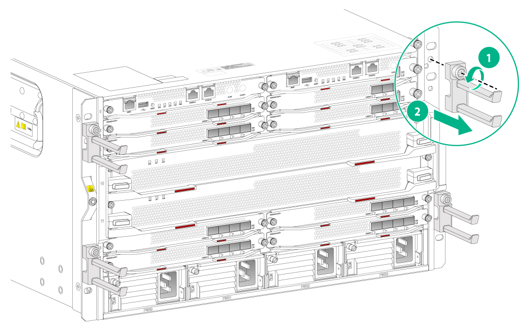
Removing cable management brackets
1. Prepare the packing bag of the cable management brackets. Make sure the bag is clean, dry, and not damaged.
2. Use a screwdriver to loosen the screws that attach the cable management brackets to the chassis, and then remove the cable management brackets.
3. Put the cable management brackets into the bag.
Figure12-2 Removing the cable management brackets
Repackaging the power module
|
|
WARNING! Before removing a power module, switch off the circuit breakers at the input end of all power cords, and remove all the power cords to avoid device damage and bodily injury. |
1. Prepare the packing bag and box of the power module. Make sure the bag is clean, dry, and not damaged.
2. Remove all power modules from the chassis, and then install filler panels to the empty slots.
For information about how to remove a power module and install a filler panel, see "Replacing a power module."
3. Put the power module into the bag.
4. Put the packed power module and power cord into the box. Place the power module in a correct direction onto the foam cushion in the box; otherwise, the power module cannot be completely seated into the foam cushion.
Repackaging the cards
1. Prepare the anti-static bag and box of the card. Make sure the bag is clean, dry, and not damaged.
2. Remove the transceiver modules from the card. If no transceiver module is installed on the card, go to the next step.
For information about how to remove a transceiver module, see "Replacing a transceiver module."
3. Remove all cards from the chassis slots, and install filler panels to the empty slots.
For information about how to remove a card and install a filler panel, see "Replacing an MPU/interface module."
4. Remove all the switching fabric modules, and install filler panels to the empty slots.
For information about how to remove a card and install a filler panel, see "Replacing a fabric module."
5. Put the cards into anti-static bags.
6. Put the packed card into the box, and tape the flaps of the box with packing tape. Place the card in a correct direction onto the foam cushion in the box; otherwise, the power module cannot be completely seated into the foam cushion.
Repackaging the router chassis
Removing the chassis from the rack
The router is heavy. If possible, use a mechanical lift to move the router.
To remove the chassis from the rack:
1. Prepare the cardboard box and packing bag of the chassis. Make sure the box and bag are clean, dry, and not damaged.
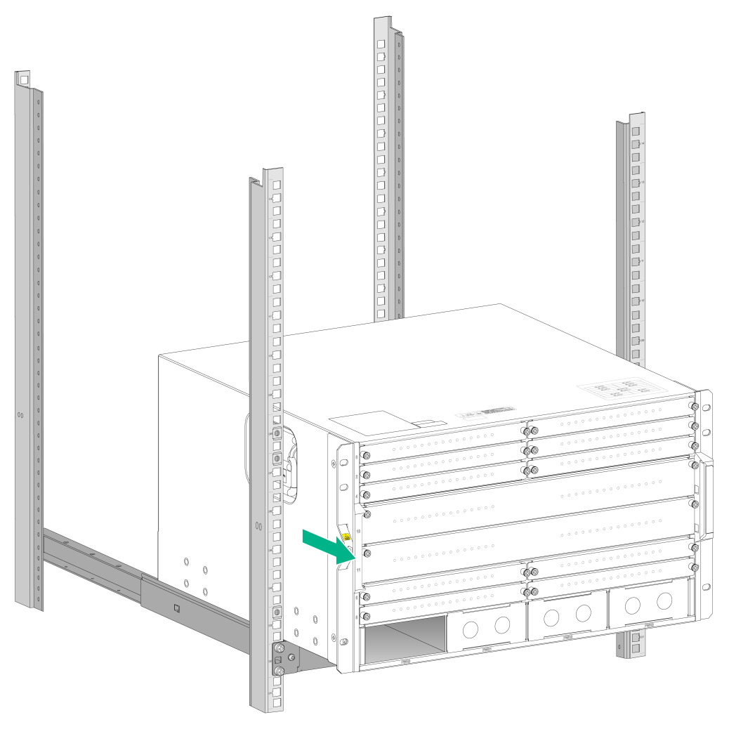
2. Use a Phillips screwdriver to loosen the screws that attach the mounting brackets to the rack.
Figure12-3 Removing the screws that secure the mounting brackets

3. Use a minimum of four people to slide the chassis outwards along the slide rails. When most part of the chassis is removed from the slide rails, lift up the chassis by holding the handles at the chassis sides to completely remove the chassis from the rack.
Figure12-4 Removing the chassis from the rack
4. Place the chassis a convenient place for handling.
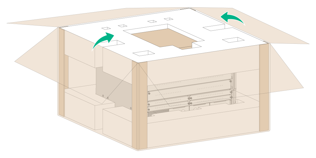
Repackaging the router chassis
1. Put the foam cushion into the paper frame.
2. Place the chassis into the foam cushion and secure the chassis.
3. Cover the chassis with the packing bag.
4. Cover the foam cushion to the chassis top, and make sure the mounting brackets seat into the internal notches of the foam cushion.
5. Erect one paper angle bead along each vertical edge of the chassis. Put the accessories box in the notch in the top middle of the foam cushion, and cover the top cap to the cardboard box.
Figure12-5 Repackaging the chassis