- Table of Contents
-
- H3C CR16000-M Routers Installation Guide-5W101
- 00-Preface
- 01-Safety precautions
- 02-Preparing for installation
- 03-Installing the router
- 04-Installing removable components
- 05-Connecting cables
- 06-Verifying the installation
- 07-Starting and configuring the router
- 08-Replacement procedures
- 09-Troubleshooting
- 10-Appendix A Engineering labels
- 11-Appendix B Cable assembling and management
- 12-Appendix C Repackaging the Router
- Related Documents
-
| Title | Size | Download |
|---|---|---|
| 05-Connecting cables | 397.74 KB |
Connecting a twisted pair cable
Connecting your router to the network through optical fibers
About transceiver modules and optical fibers
Installing a transceiver module and connecting optical fibers
5 Connecting cables
Connecting a twisted pair cable
The router provides 1000BASE-T ports. These ports use RJ-45 connectors and support auto-MDI/MDI-X. Use twisted pair cables of category-5 or above to connect the Ethernet ports of your router to the network. For more information about twisted pair cables, see "Ethernet twisted pair cable." in H3C CR16000-M Routers Hardware Information and Specifications.
To connect your router to the network through a twisted pair cable:
1. Connect one end of the twisted pair cable to the RJ-45 Ethernet port of your router.
2. Connect the other end of the twisted pair cable to the RJ-45 Ethernet port of the access device in the network.
Connecting your router to the network through optical fibers
|
|
WARNING! Disconnected optical fibers or transceiver modules might emit invisible laser light. Do not stare into beams or view directly with optical instruments when the switch is operating. |
About transceiver modules and optical fibers
To connect a fiber port, install an SFP, SFP+, or QSFP28 transceiver module in the fiber port and connect optical fibers with LC-type or MPO-type connectors to the transceiver module.
Installing a transceiver module and connecting optical fibers
|
|
WARNING! Do not stare into any open apertures of operating transceiver modules or optical fiber connectors. The laser light emitted from these apertures might hurt your eyes. |
|
|
CAUTION: · During the installation or removal process, be careful not to touch the golden plating on the transceiver module. · Before inserting a transceiver module into a port, make sure the transceiver module aligns with the port correctly. · If a transceiver module has a fiber connected, remove the fiber before installing the transceiver module. · If you are not to install an optical fiber, insert a dust plug into the transceiver module bore. |
To connect your router to the network through an optical fiber:
1. Wear an ESD wrist strap and make sure it makes good skin contact and is reliably grounded. For more information, see "Attaching an ESD wrist strap" in "Installing removable components."
2. Remove the dust plug from the target fiber port.
3. Unpack the transceiver module.
4. Pivot the clasp of the transceiver module up. Holding two sides of the transceiver module, gently push the module into the slot until you feel that the bottom spring tab catch in the slot.
Transceiver modules and fiber ports have disorientation rejection designs. If you cannot insert a transceiver module easily into a port, the orientation might be wrong. Remove and reorient the transceiver module.
In case of limited space, you can gently push against the front face of the transceiver module instead of the two sides.
5. Remove the dust covers of the optical fiber connectors, and clean both ends of the optical fiber.
6. Connect the optical fiber to the transceiver module.
¡ LC connector—Align the connector with the transceiver module and push it into the transceiver module slightly until it clicks into the place. See Figure5-1.
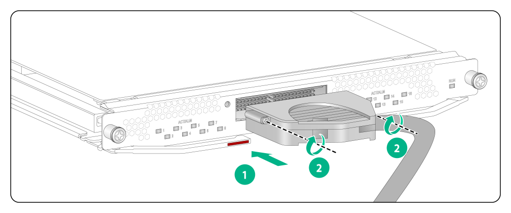
¡ MPO connector—Orient the connector with the white spot on it facing right. Insert the MPO fiber connector horizontally into the transceiver module. Push the MPO fiber connector into the transceiver module slightly until it clicks into the place. See Figure5-2.
7. Use cable ties to bind optical fibers every 150 mm (5.91 in).
8. Affix cable labels to the optical fiber to each end of the optical fiber.
Figure5-1 Connecting an LC optical fiber connector to a transceiver module
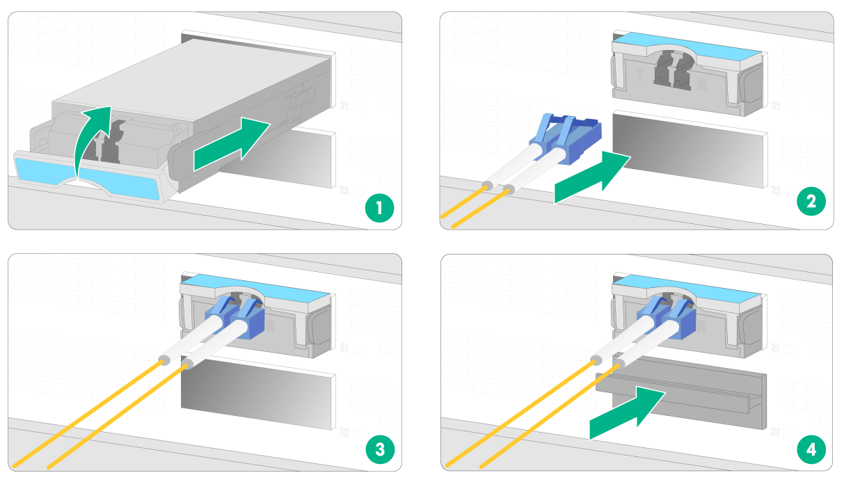
Figure5-2 Connecting an MPO optical fiber connector to a transceiver module

|
|
NOTE: The triangular pin on a transceiver module and the hole in a fiber port function together to prevent the module from disengaging from the port. |
Connecting an E1 cable
1. Wear an ESD wrist strap and make sure it makes good skin contact and is reliably grounded.
For more information, see "Attaching an ESD wrist strap" in "Installing removable components."
2. Connect the HM96 connector of the E1 cable to the interface on the subcard and use a screwdriver to fasten the screws on the connector.
3. Connect the other end of the E1 cable to the peer device.
Figure5-3 Connecting an E1 cable