- Table of Contents
-
- H3C CR16000-M Routers Installation Guide-5W101
- 00-Preface
- 01-Safety precautions
- 02-Preparing for installation
- 03-Installing the router
- 04-Installing removable components
- 05-Connecting cables
- 06-Verifying the installation
- 07-Starting and configuring the router
- 08-Replacement procedures
- 09-Troubleshooting
- 10-Appendix A Engineering labels
- 11-Appendix B Cable assembling and management
- 12-Appendix C Repackaging the Router
- Related Documents
-
| Title | Size | Download |
|---|---|---|
| 07-Starting and configuring the router | 347.67 KB |
7 Starting and configuring the router
Connecting the router to a configuration terminal
Preparing the console cable and configuration terminal
Setting up the configuration environment
Starting the router for the first time
Starting the router for the first time
7 Starting and configuring the router
The first time you access the router, you can only log in to the router locally from the console port.
If two MPUs run on the router, you can use the console port on either of the MPUs.
Connecting the router to a configuration terminal
To access the router, use a console cable to connect the router to a configuration terminal.
Preparing the console cable and configuration terminal
A console cable connects the console port on the router to a serial port on a configuration terminal to transmit configuration data. For more information about the console cable, see H3C CR16000-M Routers Hardware Information and Specifications.
Prepare the following console cable and configuration terminal for configuring the router:
· An 8-core DB9-to-RJ45 serial console cable with a crimped RJ-45 connector at one end and a DB-9 female connector at the other end.
· A PC with a serial port.
Setting up the configuration environment
|
|
CAUTION: Follow these guidelines when you connect a DB9-to-RJ45 console cable: · Identify the port marks to be sure that you connect the correct ports. · The serial ports on PCs do not support hot swapping. To connect a PC to an operating router, first connect the PC end. To disconnect a PC from an operating router, first disconnect the router end. |
To connect the router to a PC by using a DB9-to-RJ45 console cable:
1. Plug the DB-9 female connector of the DB9-to-RJ45 console cable to the serial port on the PC.
2. Connect the RJ-45 connector of the cable to the console port on the router.
Figure7-1 Connecting the router to a configuration terminal

Setting terminal parameters
To configure and manage the router through the console port, you must run a terminal emulator program, TeraTermPro or PuTTY, on your configuration terminal. You can use the emulator program to connect a network device, a Telnet site, or an SSH site. For more information about the terminal emulator programs, see the user guides for these programs.
Configure the terminal parameters as follows:
· Bits per second—9600.
· Data bits—8.
· Stop bits—1.
· Parity—None.
· Flow control—None.
Starting the router for the first time
Flowchart
To start the router for the first time, use the flowchart in Figure7-2.
Figure7-2 Flowchart for starting the router for the first time
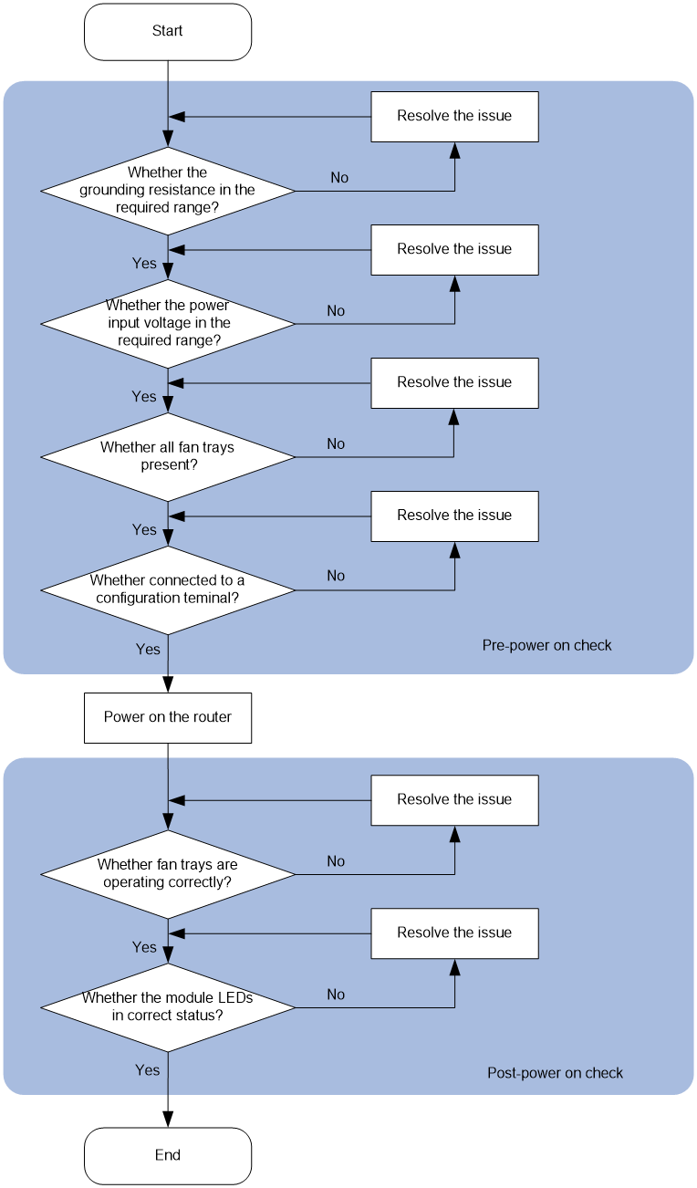
Pre-power on check
|
|
WARNING! · Before powering on the router, make sure all its switches are in the OFF position. Be sure that the input voltage is in the required range and then turn on the switches to the ON position. For the required input voltage range, see H3C CR16000-M Routers Hardware Information and Specifications. · Before powering on the router, locate all circuit breakers for the power input sources so that you can cut off power immediately in case of an emergency. |
Before powering on the router, verify that the router meets the requirements described in Table7-1.
Table7-1 Pre-power on checklist
|
No. |
Check items |
|
1 |
The resistance from the chassis to earth is less than 1 ohm. |
|
2 |
The power input voltage is as required by the router. |
|
3 |
All fan trays are present. |
|
4 |
The console cable is connected correctly, the configuration terminal has been open, and terminal parameters have been configured. |
Starting the router for the first time
Powering on the router
1. Connect the power cords to the power outlets.
2. Turn on the switch of the external power source.
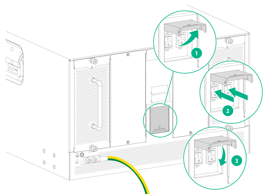
3. Open the protective cover over the power switches on the router and turn on the power switches.
4. Close the protective cover.
5. Observe the power input status LEDs on the power supplies. If the LEDs are on, the power cords are connected correctly. For more information about the power supply LEDs, see H3C CR16000-M Routers Hardware Information and Specifications.
Figure7-3 Powering on the router
Observing startup information of the router
When the router starts up, following information is output on the configuration terminal.
|
|
NOTE: Output information on the configuration terminal varies by software version. |
Press Ctrl+D to access BASIC-BOOTWARE MENU...
Press Ctrl+T to start memory test
Booting Normal Extended BootWare
The Extended BootWare is self-decompressing.........Done.
…
BootWare Validating...
Press Ctrl+B to access EXTENDED-BOOTWARE MENU...
Enter 1 and press Enter on the BootWare main menu. The system starts loading and starting the system image.
Enter your choice(0-9): 1
Loading the main image files...
Loading file flash:/temp-system.bin...........................
............................................................................
............................................................................
.............................Done.
Loading file flash:/temp-boot.bin.............................
......Done.
Image file flash:/temp-boot.bin is self-decompressing.........
................................................................Done.
System image is starting...
Line con0 is available.
Press ENTER to get started.
Press Enter. When <sysname> is displayed, the device enters user view and you can configure the router.
Post-power on check
After the router starts up, verify that the router is operating correctly.
· If the ventilation system operates correctly after the router is powered on, you can hear rotation of fan trays and feel air exhausted from the air outlet vents.
· If the router is operating correctly, the module LEDs will be in status as described in Table7-2. If the LEDs are not in status as described in Table7-2, the router might be operating incorrectly. For more information about the LEDs, see H3C CR16000-M Routers Hardware Information and Specifications. To resolve the issues based on the LEDs, see "Troubleshooting".
Table7-2 LED status when the router is operating correctly
|
Module |
LED |
Status |
|
|
MPU |
MGMENT |
LINK |
Steady on |
|
ACT |
Flashing |
||
|
RUN |
Flashing (0.5 Hz) |
||
|
ACT |
Steady on |
||
|
ALM |
Off |
||
|
FAN |
Steady green |
||
|
PWR |
Steady green |
||
|
Interface module |
RUN |
Flashing (0.5 Hz) |
|
|
Switching fabric module |
RUN |
Flashing (0.5 Hz) |
|
|
ACT |
Steady on |
||
|
ALM |
Off |
||
|
Power supply |
PSR2500-12A power supply |
AC |
Steady green |
|
DC |
Steady green |
||
|
PSR2400-12D/PSR2400-D power supply |
DC/FLT |
Steady green |
|
|
INP OK |
Steady green |
||
|
PSR2500B-12AHD-F power supply |
IN |
Steady green |
|
|
OUT |
Steady green |
||
|
Fan tray |
RUN |
Steady green |
|
Configuring the router
At the first startup of the router, you are required to configure basic parameters for the router. For more information, see H3C CR16000-M Routers Fundamentals Configuration Guide and H3C CR16000-M Routers Fundamentals Command Reference.
