- Table of Contents
-
- H3C WX6103 Access Controller Switch Interface Board Configuration Guide-6W102
- 00-Preface
- 01-Login Configuration
- 02-VLAN Configuration
- 03-IP Addressing and IP Performance Configuration
- 04-QinQ-BPDU Tunneling Configuration
- 05-Port Correlation Configuration
- 06-Link Aggregation Configuration
- 07-MAC Address Table Management Configuration
- 08-Port Security Configuration
- 09-MSTP Configuration
- 10-IP Routing-GR Overview Configuration
- 11-IPv4 Routing Configuration
- 12-IP Source Guard Configuration
- 13-DLDP Configuration
- 14-Multicast Configuration
- 15-LLDP Configuration
- 16-sFlow Configuration
- 17-ARP Configuration
- 18-DHCP Configuration
- 19-ACL Configuration
- 20-QoS Configuration
- 21-Port Mirroring Configuration
- 22-UDP Helper Configuration
- 23-SNMP-RMON Configuration
- 24-NTP Configuration
- 25-DNS Configuration
- 26-File System Management Configuration
- 27-Information Center Configuration
- 28-System Maintaining and Debugging Configuration
- 29-NQA Configuration
- 30-SSH Configuration
- 31-SSL-HTTPS Configuration
- 32-PKI Configuration
- 33-Track Configuration
- 34-Acronyms
- 35-Index
- Related Documents
-
| Title | Size | Download |
|---|---|---|
| 21-Port Mirroring Configuration | 131.76 KB |
Table of Contents
1 Port Mirroring Configuration
Introduction to Port Mirroring
Classification of Port Mirroring
Other Functions Supported by Port Mirroring
Configuring Local Port Mirroring
Configuring Remote Port Mirroring
Configuring a Remote Source Mirroring Group
Configuring a Remote Destination Port Mirroring Group
Port Mirroring Configuration Examples
Local Port Mirroring Configuration Example
Remote Port Mirroring Configuration Example
![]()
The term switch in this document refers to a switch in a generic sense or an access controller configured with the switching function unless otherwise specified.
When configuring port mirroring, go to these sections for information you are interested in:
l Introduction to Port Mirroring
l Configuring Local Port Mirroring
l Configuring Remote Port Mirroring
l Port Mirroring Configuration Examples
Introduction to Port Mirroring
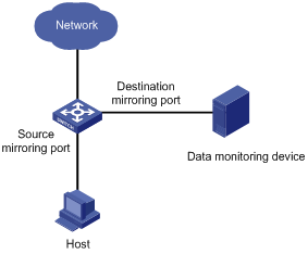
Port mirroring allows you to duplicate the packets passing specified ports to the destination mirroring port. As destination mirroring ports usually have data monitoring devices connected to them, you can analyze the packets duplicated to the destination mirroring port on these devices so as to monitor and troubleshoot the network.
Figure 1-1 A port mirroring implementation
Classification of Port Mirroring
There are two kinds of port mirroring: local port mirroring and remote port mirroring.
l Local port mirroring copies packets passing through one or more ports (known as source ports) of a device to the monitor port (also destination port) for analysis and monitoring purpose. In this case, the source ports and the destination port are located on the same device.
l Remote port mirroring implements port mirroring between multiple devices. That is, the source ports and the destination port can be located on different devices in a network. Currently, remote port mirroring can only be implemented on Layer 2.
Implementing Port Mirroring
Port mirroring is implemented through port mirroring groups, which fall into these three categories: local port mirroring group, remote source port mirroring group, and remote destination port mirroring group. Two port mirroring implementation modes are introduced in the following section.
Local port mirroring
Local port mirroring is implemented by local port mirroring group.
In this mode, the source ports and the destination port are in the same local port mirroring group. Packets passing through the source ports are duplicated and then forwarded to the destination port.
Remote port mirroring
Remote port mirroring is achieved through the cooperation of remote source port mirroring group and remote destination port mirroring group.
Figure 1-2 illustrates a remote port mirroring implementation.
Figure 1-2 A remote mirroring implementation
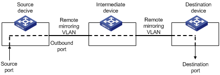
The devices in Figure 1-2 function as follows:
l Source device
Source device contains source mirroring ports, and remote source port mirroring groups are created on source devices. A source device duplicates the packets passing the source ports on it and sends them to the outbound port. The packets are then broadcast in the remote mirroring VLAN and are received by the intermediate device or destination device.
l Intermediate device
Intermediate devices are used to connect source devices and destination devices. An intermediate device forwards the mirrored packets to the next intermediate device or the destination device. If the source device is directly connected to the destination device, no intermediate device is needed. In a remote mirroring VLAN, the source devices and the destination device need to be able to communicate with one another on Layer 2.
l Destination device
Destination device contains destination mirroring port, and remote destination port mirroring groups are created on destination devices. Upon receiving a mirrored packet, the destination device checks to see if the VLAN ID of the received packet is the same as that of the remote mirroring VLAN of the remote destination port mirroring group. If yes, the destination device forwards the packet to the monitoring device through the destination mirroring port.
Other Functions Supported by Port Mirroring
In addition, in a port mirroring group, a destination port can monitor multiple source ports simultaneously in the mirroring group.
Configuring Local Port Mirroring
Follow these steps to configure local port mirroring:
|
Use the command… |
Remarks |
||
|
Enter system view |
system-view |
— |
|
|
Create a local mirroring group |
mirroring-group group-id local |
Required |
|
|
Add ports to the port mirroring group as source ports |
In system view |
mirroring-group group-id mirroring-port mirroring-port-list { both | inbound | outbound } |
Use either approach. You can add ports to a port mirroring group as source ports in either system view or interface view. In system view, you can add multiple ports to a port mirroring group at one time. While in interface view, you can only add the current port to a port mirroring group. |
|
In interface view |
interface interface-type interface-number |
||
|
[ mirroring-group group-id ] mirroring-port { both | inbound | outbound } |
|||
|
quit |
|||
|
Add a port to the mirroring group as the destination port |
In system view |
mirroring-group group-id monitor-port monitor-port-id |
Use either approach. You can add a destination port to a port mirroring group in either system view or interface view. They achieve the same purpose. |
|
In interface view |
interface interface-type interface-number |
||
|
[ mirroring-group group-id ] monitor-port |
|||
![]()
l A local mirroring group is effective only when it has both source ports and the destination port configured.
l It is not recommended to enable STP, RSTP or MSTP on the destination port; otherwise, the mirroring function may be affected.
l Do not use the destination mirroring port for any purpose other than port mirroring.
l The source ports and the destination port cannot be the member ports of the current mirroring group.
l Before adding the destination port for a port mirroring group, make sure the port mirroring group exists. A mirroring group can have only one destination port.
Configuring Remote Port Mirroring
![]()
You can configure a remote source port mirroring group as well as a remote destination port mirroring group on a WX6103 access controller switch interface board.
Configuring a Remote Source Mirroring Group
Follow these steps to configure a remote port mirroring group
|
To do… |
Use the command… |
Remarks |
|
|
Enter system view |
system-view |
— |
|
|
Create a remote source mirroring group |
mirroring-group group-id remote-source |
Required |
|
|
Add ports to the mirroring group as source ports |
In system view |
mirroring-group group-id mirroring-port mirroring-port-list { both | inbound | outbound } |
Use either approach. You can add ports to a source port mirroring group in either system view or interface view. They achieve the same purpose. |
|
In interface view |
interface interface-type interface-number |
||
|
[ mirroring-group group-id ] mirroring-port { both | inbound | outbound } |
|||
|
quit |
|||
|
Add a port to the mirroring group as the outbound mirroring port |
In system view |
mirroring-group group-id monitor-egress monitor-egress-port-id |
Use either approach. You can add ports to a source mirroring group in either system view or interface view. They achieve the same purpose. |
|
In interface view |
interface interface-type interface-number |
||
|
mirroring-group group-id monitor-egress |
|||
|
quit |
|||
|
Configure the remote port mirroring VLAN for the mirroring group |
mirroring-group group-id remote-probe vlan rprobe-vlan-id |
Required |
|
![]()
l All ports in a remote mirroring group belong to the same device. A remote source mirroring group can have only one outbound mirroring port.
l The outbound mirroring port cannot be a member port of the current mirroring group.
l It is not recommended to add the source ports to a remote VLAN, which can be used for remote mirroring only.
l It is not recommended to configure STP, RSTP, MSTP, 802.1x, IGMP Snooping, static ARP and MAC address learning on the outbound mirroring port; otherwise, the mirroring function may be affected.
l Only existing static VLANs can be configured as remote port mirroring VLANs. To remove a VLAN operating as a remote port mirroring VLAN, you need to restore it to a normal VLAN first. A remote port mirroring group gets invalid if the corresponding remote port mirroring VLAN is removed.
l A port can belong to only one port mirroring group. A VLAN can be the remote port mirroring VLAN of only one port mirroring group.
Configuring a Remote Destination Port Mirroring Group
Follow these steps to configure a remote destination port mirroring group:
|
To do… |
Use the command… |
Remarks |
|
|
Enter system view |
system-view |
— |
|
|
Create a remote destination port mirroring group |
mirroring-group group-id remote-destination |
Required |
|
|
Configure the remote port mirroring VLAN for the port mirroring group |
mirroring-group group-id remote-probe vlan rprobe-vlan-id |
Required |
|
|
Add a port to the port mirroring group as the destination port |
In system view |
mirroring-group group-id monitor-port monitor-port-id |
Use either approach. You can add a port to a remote port mirroring group as the destination port in either system view or interface view. They achieve the same purpose. |
|
In interface view |
interface interface-type interface-number |
||
|
[ mirroring-group group-id ] monitor-port |
|||
|
quit |
|||
|
Enter destination interface view |
interface interface-type interface-number |
— |
|
|
Add the port to the remote port mirroring VLAN |
The port is an access port |
port access vlan rprobe-vlan-id |
Perform one of these three operations according to the port type. |
|
The port is a trunk port |
port trunk permit vlan rprobe-vlan-id |
||
|
The port is a hybrid port |
port hybrid vlan rprobe-vlan-id { tagged | untagged } |
||
![]()
l The remote destination mirroring port cannot be a member port of the current mirroring group.
l The remote destination mirroring port can be an access, trunk, or hybrid port. It must be assigned to the remote mirroring VLAN.
l Do not enable STP, RSTP or MSTP on the remote destination mirroring port. Otherwise, the mirroring function may be affected.
l Do not use the remote destination mirroring port for any purpose other than port mirroring.
l Only existing static VLANs can be configured as remote port mirroring VLANs. To remove a VLAN operating as a remote port mirroring VLAN, you need to restore it to a normal VLAN first. A remote port mirroring group gets invalid if the corresponding remote port mirroring VLAN is removed.
l Use a remote port mirroring VLAN for remote port mirroring only.
l A port can belong to only one port mirroring group. A VLAN can be the remote port mirroring VLAN of only one port mirroring group.
Displaying Port Mirroring
Follow these steps to display port mirroring:
|
To do… |
Use the command… |
Remarks |
|
Display the configuration of a port mirroring group |
display mirroring-group { group-id | all | local | remote-destination | remote-source } |
Available in any view |
Port Mirroring Configuration Examples
Local Port Mirroring Configuration Example
Network requirements
The departments of a company connect to each other through Ethernet switches:
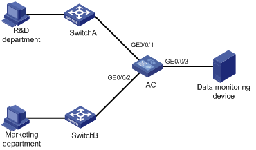
l Research and Development (R&D) department is connected to AC through GigabitEthernet 0/0/1.
l Marketing department is connected to AC through GigabitEthernet 0/0/2.
l Data monitoring device is connected to AC through GigabitEthernet 0/0/3
The administrator wants to monitor the packets received on and sent from the R&D department and the marketing department through the data monitoring device.
Use the local port mirroring function to meet the requirement. Perform the following configurations on AC.
l Configure GigabitEthernet 0/0/1 and GigabitEthernet 0/0/2 as mirroring source ports.
l Configure GigabitEthernet 0/0/3 as the mirroring destination port.
Network diagram
Figure 1-3 Network diagram for local port mirroring configuration
Configuration procedure
Configure AC.
# Create a local port mirroring group.
<AC> system-view
[AC] mirroring-group 1 local
# Add port GigabitEthernet 0/0/1 and GigabitEthernet 0/0/2 to the port mirroring group as source ports. Add port GigabitEthernet 0/0/3 to the port mirroring group as the destination port.
[AC] mirroring-group 1 mirroring-port GigabitEthernet 0/0/1 GigabitEthernet 0/0/2 both
[AC] mirroring-group 1 monitor-port GigabitEthernet 0/0/3
# Display the configuration of all the port mirroring groups.
[AC] display mirroring-group all
mirroring-group 1:
type: local
status: active
mirroring port:
GigabitEthernet0/0/1 both
GigabitEthernet0/0/2 both
monitor port: GigabitEthernet0/0/3
After finishing the configuration, you can monitor all the packets received and sent by R&D department and Marketing department on the Data monitoring device.
Remote Port Mirroring Configuration Example
Network requirements
The departments of a company connect to each other through Ethernet switches:
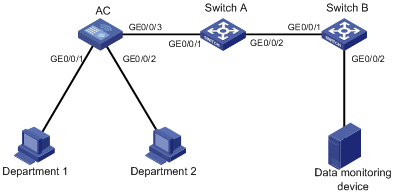
l Department 1 is connected to GigabitEthernet 0/0/1 of AC.
l Department 2 is connected to GigabitEthernet 0/0/2 of AC.
l GigabitEthernet 0/0/3 of AC connects to GigabitEthernet 0/0/1 of Switch A.
l GigabitEthernet 0/0/2 of Switch A connects to GigabitEthernet 0/0/1 of Switch B.
l The data monitoring device is connected to GigabitEthernet 0/0/2 of Switch B.
The administrator wants to monitor the packets sent from Department 1 and 2 through the data monitoring device.
Use the remote port mirroring function to meet the requirement. Perform the following configurations:
l Use AC as the source device, Switch A as the intermediate device, and Switch B as the destination device.
l On AC, create a remote source mirroring group; create VLAN 2 and configure it as the remote port mirroring VLAN; add port GigabitEthernet 0/0/1 and GigabitEthernet 0/0/2 to the port mirroring group as two source ports. Configure port GigabitEthernet 0/0/3 as the outbound mirroring port.
l Configure port GigabitEthernet 0/0/3 of AC, port GigabitEthernet 0/0/1 and GigabitEthernet 0/0/2 of Switch A, and port GigabitEthernet 0/0/1 of Switch B as trunk ports and configure them to permit packets of VLAN 2.
l Create a remote destination mirroring group on Switch B. Configure VLAN 2 as the remote port mirroring VLAN and port GigabitEthernet 0/0/2, to which the data monitoring device is connected, as the destination port.
Network diagram
Figure 1-4 Network diagram for remote port mirroring configuration
Configuration procedure
1) Configure AC (the source device).
# Create a remote source port mirroring group.
<AC> system-view
[AC] mirroring-group 1 remote-source
# Create VLAN 2.
[AC] vlan 2
[AC-vlan2] quit
# Configure VLAN 2 as the remote port mirroring VLAN of the remote port mirroring group. Add port GigabitEthernet 0/0/1 and GigabitEthernet 0/0/2 to the remote port mirroring group as source ports. Configure port GigabitEthernet 0/0/3 as the outbound mirroring port.
[AC] mirroring-group 1 remote-probe vlan 2
[AC] mirroring-group 1 mirroring-port GigabitEthernet 0/0/1 GigabitEthernet 0/0/2 inbound
[AC] mirroring-group 1 monitor-egress GigabitEthernet 0/0/3
# Configure port GigabitEthernet 0/0/3 as a trunk port and configure the port to permit the packets of VLAN 2.
[AC] interface GigabitEthernet 0/0/3
[AC-GigabitEthernet0/0/3] port link-type trunk
[AC-GigabitEthernet0/0/3] port trunk permit vlan 2
2) Configure Switch A (the intermediate device).
# Configure port GigabitEthernet 0/0/1 as a trunk port and configure the port to permit the packets of VLAN 2.
<SwitchA> system-view
[SwitchA] interface GigabitEthernet 0/0/1
[SwitchA-GigabitEthernet0/0/1] port link-type trunk
[SwitchA-GigabitEthernet0/0/1] port trunk permit vlan 2
[SwitchA-GigabitEthernet0/0/1] quit
# Configure port GigabitEthernet 0/0/2 as a trunk port and configure the port to permit the packets of VLAN 2.
[SwitchA] interface GigabitEthernet 0/0/2
[SwitchA-GigabitEthernet0/0/2] port link-type trunk
[SwitchA-GigabitEthernet0/0/2] port trunk permit vlan 2
3) Configure Switch B (the destination device).
# Configure port GigabitEthernet 0/0/1 as a trunk port and configure the port to permit the packets of VLAN 2.
<SwitchB> system-view
[SwitchB] interface GigabitEthernet 0/0/1
[SwitchB-GigabitEthernet0/0/1] port link-type trunk
[SwitchB-GigabitEthernet0/0/1] port trunk permit vlan 2
[SwitchB-GigabitEthernet0/0/1] quit
# Create a remote destination port mirroring group.
[SwitchB] mirroring-group 1 remote-destination
# Create VLAN 2.
[SwitchB] vlan 2
[SwitchB-vlan2] quit
# Configure VLAN 2 as the remote port mirroring VLAN of the remote destination port mirroring group. Add port GigabitEthernet 0/0/2 to the remote destination port mirroring group as the destination port.
[SwitchB] mirroring-group 1 remote-probe vlan 2
[SwitchB] mirroring-group 1 monitor-port GigabitEthernet 0/0/2
[SwitchB] interface GigabitEthernet 0/0/2
[SwitchB-GigabitEthernet0/0/2] port access vlan 2
After finishing the configuration, you can monitor all the packets sent by Department 1 and Department 2 on the Data monitoring device.
