- Table of Contents
-
- H3C WX6103 Access Controller Switch Interface Board Configuration Guide-6W102
- 00-Preface
- 01-Login Configuration
- 02-VLAN Configuration
- 03-IP Addressing and IP Performance Configuration
- 04-QinQ-BPDU Tunneling Configuration
- 05-Port Correlation Configuration
- 06-Link Aggregation Configuration
- 07-MAC Address Table Management Configuration
- 08-Port Security Configuration
- 09-MSTP Configuration
- 10-IP Routing-GR Overview Configuration
- 11-IPv4 Routing Configuration
- 12-IP Source Guard Configuration
- 13-DLDP Configuration
- 14-Multicast Configuration
- 15-LLDP Configuration
- 16-sFlow Configuration
- 17-ARP Configuration
- 18-DHCP Configuration
- 19-ACL Configuration
- 20-QoS Configuration
- 21-Port Mirroring Configuration
- 22-UDP Helper Configuration
- 23-SNMP-RMON Configuration
- 24-NTP Configuration
- 25-DNS Configuration
- 26-File System Management Configuration
- 27-Information Center Configuration
- 28-System Maintaining and Debugging Configuration
- 29-NQA Configuration
- 30-SSH Configuration
- 31-SSL-HTTPS Configuration
- 32-PKI Configuration
- 33-Track Configuration
- 34-Acronyms
- 35-Index
- Related Documents
-
| Title | Size | Download |
|---|---|---|
| 11-IPv4 Routing Configuration | 953.36 KB |
Table of Contents
1 Static Routing Configuration
Application Environment of Static Routing
Detecting Reachability of the Static Route’s Nexthop
Detecting Nexthop Reachability Through Track
Displaying and Maintaining Static Routes
Configuring RIP Basic Functions
Configuring an Additional Routing Metric
Configuring RIPv2 Route Summarization
Disabling Host Route Reception
Configuring Inbound/Outbound Route Filtering
Configuring a Priority for RIP
Configuring RIP Route Redistribution
Configuring RIP Network Optimization
Configuring Split Horizon and Poison Reverse
Enabling Zero Field Check on Incoming RIPv1 Messages
Enabling Source IP Address Check on Incoming RIP Updates
Configuring RIPv2 Message Authentication
Displaying and Maintaining RIP
OSPF Area Partition and Route Summarization
Classification of OSPF Networks
Configuring OSPF Basic Functions
Configuring a Router Priority for an OSPF Interface
Configuring OSPF Area Parameters
Configuring OSPF Route Control
Configuring OSPF Route Summarization
Configuring OSPF Inbound Route Filtering
Configuring ABR Type-3 LSA Filtering
Configuring an OSPF Cost for an Interface
Configuring the Maximum Number of OSPF Routes
Configuring the Maximum Number of Load-balanced Routes
Configuring a Priority for OSPF
Configuring OSPF Route Redistribution
Configuring OSPF Network Optimization
Configuring OSPF Packet Timers
Specifying an LSA Transmission Delay
Specifying SPF Calculation Interval
Specifying the LSA Minimum Repeat Arrival Interval
Specifying the LSA Generation Interval
Disabling Interfaces from Sending OSPF Packets
Configuring OSPF Authentication
Adding the Interface MTU into DD Packets
Configuring the Maximum Number of External LSAs in LSDB
Making External Route Selection Rules Defined in RFC1583 Compatible
Logging Neighbor State Changes
Configuring OSPF Network Management
Enabling the Advertisement and Reception of Opaque LSAs
Configuring OSPF Graceful Restart
Configuring the OSPF GR Helper
Triggering OSPF Graceful Restart
Displaying and Maintaining OSPF
Configuring OSPF Basic Functions
Configuring OSPF Virtual Links
OSPF Graceful Restart Configuration Example
Troubleshooting OSPF Configuration
No OSPF Neighbor Relationship Established
When configuring a static route, go to these sections for information you are interested in:
l Detecting Reachability of the Static Route’s Nexthop
l Displaying and Maintaining Static Routes
![]()
The term switch in this document refers to a switch in a generic sense or an access controller configured with the switching function unless otherwise specified.
Introduction
Static Route
A static route is a special route that is manually configured by the network administrator. If a network’s topology is simple, you only need to configure static routes for the network to work normally. The proper configuration and usage of static routes can improve network performance and ensure bandwidth for important network applications.
The disadvantage of using static routes is that they cannot adapt to network topology changes. If a fault or a topological change occurs in the network, the routes will be unreachable and the network breaks. In this case, the network administrator has to modify the static routes manually.
Default Route
A router selects the default route only when it cannot find any matching entry in the routing table.
If there is no default route and the destination address of the packet fails to match any entry in the routing table, the packet will be discarded and an ICMP packet will be sent to the source to report that the destination or the network is unreachable.
You can create the default route with both destination and mask being 0.0.0.0, and some dynamic routing protocols, such as OSPF, RIP and IS-IS, can also generate the default route.
Application Environment of Static Routing
Before configuring a static route, you need to know the following concepts:
1) Destination address and mask
In the ip route-static command, an IPv4 address is in dotted decimal format and a mask can be either in dotted decimal format or in the form of mask length (the digits of consecutive 1s in the mask).
2) Output interface and next hop address
While configuring a static route, you can specify either the output interface or the next hop address depending on the specific occasion. The next hop address can not be a local interface IP address; otherwise, the route configuration will not take effect.
In fact, all the route entries must have a next hop address. When forwarding a packet, a router first searches the routing table for the route to the destination address of the packet. The system can find the corresponding link layer address and forward the packet only after the next hop address is specified.
When specifying the output interface, note that:
l If the output interface is a NULL 0 interface, there is no need to configure the next hop address.
l You are not recommended to specify a broadcast interface (such as VLAN interface) as the output interface, because a broadcast interface may have multiple next hops. If you have to do so, you must specify the corresponding next hop for the output interface.
3) Other attributes
You can configure different preferences for different static routes so that route management policies can be applied more flexibly. For example, specifying the same preference for different routes to the same destination enables load sharing, while specifying different preferences for these routes enables route backup.
Configuring a Static Route
Configuration Prerequisites
Before configuring a static route, you need to configure the IP addresses for related interfaces.
Configuration Procedure
Follow these steps to configure a static route:
|
To do… |
Use the command… |
Remarks |
|
Enter system view |
system-view |
— |
|
Configure a static route |
ip route-static dest-address { mask | mask-length } { next-hop-address | interface-type interface-number [ next-hop-address ] } [ preference preference-value ] [ tag tag-value ] [ description description-text ] |
Required By default, preference for static routes is 60, tag is 0, and no description information is configured. |
|
Configure the default preference for static routes |
ip route-static default-preference default-preference-value |
Optional 60 by default |
![]()
l When configuring a static route, the static route does not take effect if you specify the next hop address first and then configure it as the IP address of a local interface, such as a VLAN interface.
l If you do not specify the preference when configuring a static route, the default preference will be used. Reconfiguring the default preference applies only to newly created static routes.
l You can flexibly control static routes by configuring tag values and using the tag values in the route policy.
l If the destination IP address and mask are both configured as 0.0.0.0 with the ip route-static command, the route is the default route.
Detecting Reachability of the Static Route’s Nexthop
If a static route fails due to a topology change or a fault, the connection will be interrupted. To improve network stability, the system needs to detect reachability of the static route’s next hop and switch to a backup route once the next hop is unreachable.
Detecting Nexthop Reachability Through Track
If you specify the nexthop but not outgoing interface when configuring a static route, you can associate the static route with a track entry to check the static route validity:
l When the track entry is positive, the static route's nexthop is reachable and the static route takes effect.
l When the track entry is negative, the static route's nexthop is unreachable and the static route is invalid. For details about track, refer to Track in H3C WX6103 Access Controller Switch Interface Board Configuration Guide.
Network requirements
To detect the reachability of a static route's nexthop through a Track entry, you need to create a Track first. For detailed Track configuration procedure, refer to Track in H3C WX6103 Access Controller Switch Interface Board Configuration Guide.
Configuration procedure
Follow these steps to detect the reachability of a static route's nexthop through Track:
|
To do… |
Use the command… |
Remarks |
|
Enter system view |
system-view |
— |
|
Associate the static route with a track entry |
ip route-static dest-address { mask | mask-length } next-hop-address track track-entry-number [ preference preference-value ] [ tag tag-value ] [ description description-text ] |
Required Not configured by default |
![]()
l To configure this feature for an existing static route, simply associate the static route with a track entry. For a non-existent static route, configure it and associate it with a Track entry.
l If a static route needs route recursion, the associated track entry must monitor the nexthop of the recursive route instead of that of the static route; otherwise, a valid route may be mistakenly considered invalid.
Displaying and Maintaining Static Routes
|
To do… |
Use the command… |
Remarks |
|
Display the current configuration information |
display current-configuration |
Available in any view |
|
Display the brief information of the IP routing table |
display ip routing-table |
|
|
Display the detailed information of the IP routing table |
display ip routing-table verbose |
|
|
View information of static routes |
display ip routing-table protocol static [ inactive | verbose ] |
|
|
Delete all the static routes |
delete static-routes all |
Available In system view |
Configuration Example
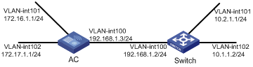
Network requirements
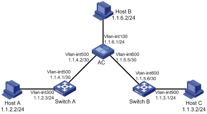
The IP addresses and masks of the switches, access controller (AC), and hosts are shown in the following figure. Static routes are required for interconnection between any two hosts.
Network diagram
Figure 1-1 Network diagram for static route configuration
Configuration procedure
1) Configuring IP addresses for interfaces (omitted)
2) Configuring static routes
# Configure a default route on Switch A
<Switch A> system-view
[Switch A] ip route-static 0.0.0.0 0.0.0.0 1.1.4.2
# Configure two static routes on the AC
<AC> system-view
[AC] ip route-static 1.1.2.0 255.255.255.0 1.1.4.1
[AC] ip route-static 1.1.3.0 255.255.255.0 1.1.5.6
# Configure a default route on Switch B
<Switch B> system-view
[Switch B] ip route-static 0.0.0.0 0.0.0.0 1.1.5.5
3) Configure the hosts
The default gateways for the three hosts A, B and C are 1.1.2.3, 1.1.6.1 and 1.1.3.1 respectively. The configuration procedure is omitted.
4) Display the configuration result
# Display the IP routing table of Switch A.
[Switch A] display ip routing-table
Routing Tables: Public
Destinations : 7 Routes : 7
Destination/Mask Proto Pre Cost NextHop Interface
0.0.0.0/0 Static 60 0 1.1.4.2 Vlan500
1.1.2.0/24 Direct 0 0 1.1.2.3 Vlan300
1.1.2.3/32 Direct 0 0 127.0.0.1 InLoop0
1.1.4.0/30 Direct 0 0 1.1.4.1 Vlan500
1.1.4.1/32 Direct 0 0 127.0.0.1 InLoop0
127.0.0.0/8 Direct 0 0 127.0.0.1 InLoop0
127.0.0.1/32 Direct 0 0 127.0.0.1 InLoop0
# Display the IP routing table of the AC.
[AC] display ip routing-table
Routing Tables: Public
Destinations : 10 Routes : 10
Destination/Mask Proto Pre Cost NextHop Interface
1.1.2.0/24 Static 60 0 1.1.4.1 Vlan500
1.1.3.0/24 Static 60 0 1.1.5.6 Vlan600
1.1.4.0/30 Direct 0 0 1.1.4.2 Vlan500
1.1.4.2/32 Direct 0 0 127.0.0.1 InLoop0
1.1.5.0/30 Direct 0 0 1.1.5.5 Vlan600
1.1.5.5/32 Direct 0 0 127.0.0.1 InLoop0
127.0.0.0/8 Direct 0 0 127.0.0.1 InLoop0
127.0.0.1/32 Direct 0 0 127.0.0.1 InLoop0
1.1.6.0/24 Direct 0 0 1.1.6.1 Vlan100
1.1.6.1/32 Direct 0 0 127.0.0.1 InLoop0
# From Host A, use the ping command to verify the network layer reachability to Host B and Host C.
2 RIP Configuration
![]()
l The term “router” in this document refers to a router in a generic sense or a Layer 3 switch.
l The switch interface board only supports single RIP process.
When configuring RIP, go to these sections for information you are interested in:
l Configuring RIP Basic Functions
l Configuring RIP Route Control
l Configuring RIP Network Optimization
l Displaying and Maintaining RIP
RIP Overview
RIP is a simple Interior Gateway Protocol (IGP), mainly used in small-sized networks, such as academic networks and simple LANs. RIP is not applicable to complex networks.
RIP is still widely used in practical networking due to easier implementation, configuration and maintenance than OSPF and IS-IS.
RIP Working Mechanism
Basic concepts
RIP is a distance vector routing protocol, using UDP packets for exchanging information through port 520.
RIP uses a hop count to measure the distance to a destination. The hop count is known as the metric. The hop count from a router to a directly connected network is 0. The hop count from one router to a directly connected router is 1. To limit convergence time, the range of RIP metric value is from 0 to 15. A metric value of 16 (or bigger) is considered infinite, which means the destination network is unreachable. That is why RIP is not suitable for large-scaled networks.
RIP prevents routing loops by implementing the split horizon and poison reverse functions.
RIP routing table
A RIP router has a routing table containing routing entries of all reachable destinations, and each routing entry contains:
l Destination address: IP address of a host or a network.
l Next hop: IP address of the adjacent router’s interface to reach the destination.
l Egress interface: Packet outgoing interface.
l Metric: Cost from the local router to the destination.
l Route time: Time elapsed since the routing entry was last updated. The time is reset to 0 every time the routing entry is updated.
l Route tag: Identifies a route, used in a route policy to flexibly control routes. For information about route policy, refer to Route Policy in H3C WX6103 Access Controller Switch Interface Board Configuration Guide
RIP timers
RIP employs four timers, update, timeout, suppress, and garbage-collect.
l The update timer defines the interval between routing updates.
l The timeout timer defines the route aging time. If no update for a route is received within the aging time, the metric of the route is set to 16 in the routing table.
l The suppress timer defines how long a RIP route stays in the suppressed state. When the metric of a route is 16, the route enters the suppressed state. In the suppressed state, only routes which come from the same neighbor and whose metric is less than 16 will be received by the router to replace unreachable routes.
l The garbage-collect timer defines the interval from when the metric of a route becomes 16 to when it is deleted from the routing table. During the garbage-collect timer length, RIP advertises the route with the routing metric set to 16. If no update is announced for that route after the garbage-collect timer expires, the route will be deleted from the routing table.
Routing loops prevention
RIP is a distance vector (D-V) routing protocol. Since a RIP router advertises its own routing table to neighbors, routing loops may occur.
RIP uses the following mechanisms to prevent routing loops.
l Counting to infinity. The metric value of 16 is defined as unreachable. When a routing loop occurs, the metric value of the route will increment to 16.
l Split horizon. A router does not send the routing information learned from a neighbor to the neighbor to prevent routing loops and save bandwidth.
l Poison reverse. A router sets the metric of routes received from a neighbor to 16 and sends back these routes to the neighbor to help delete useless information from the neighbor’s routing table.
l Triggered updates. A router advertises updates once the metric of a route is changed rather than after the update period expires to speed up network convergence.
Operation of RIP
The following procedure describes how RIP works.
1) After RIP is enabled, the router sends Request messages to neighboring routers. Neighboring routers return Response messages including information about their routing tables.
2) After receiving such information, the router updates its local routing table, and sends triggered update messages to its neighbors. All routers on the network do the same to keep the latest routing information.
3) By default, a RIP router sends its routing table to neighbors every 30 seconds.
4) RIP ages out routes by adopting an aging mechanism to keep only valid routes.
RIP Version
RIP has two versions, RIPv1 and RIPv2.
RIPv1, a classful routing protocol, supports message advertisement via broadcast only. RIPv1 protocol messages do not carry mask information, which means it can only recognize routing information of natural networks such as Class A, B, C. That is why RIPv1 does not support discontiguous subnets.
RIPv2 is a classless routing protocol. Compared with RIPv1, RIPv2 has the following advantages.
l Supporting route tags. Route tags are used in routing policies to flexibly control routes.
l Supporting masks, route summarization and Classless Inter-Domain Routing (CIDR).
l Supporting designated next hops to select the best next hops on broadcast networks.
l Supporting multicast routing update to reduce resource consumption.
l Supporting plain text authentication and MD5 authentication to enhance security.
![]()
RIPv2 has two types of message transmission: broadcast and multicast. Multicast is the default type using 224.0.0.9 as the multicast address. The interface working in the RIPv2 broadcast mode can also receive RIPv1 messages.
RIP Message Format
RIPv1 message format
A RIPv1 message consists of a header and up to 25 route entries.
Figure 2-1 shows the format of RIPv1 message.
Figure 2-1 RIPv1 Message Format
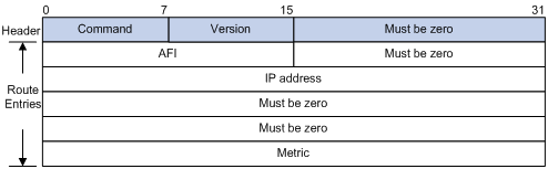
l Command: Type of message. 1 indicates request, and 2 indicates response.
l Version: Version of RIP, 0x01 for RIPv1.
l AFI: Address Family Identifier, 2 for IP.
l IP Address: Destination IP address of the route. It can be a natural network, subnet or a host address.
l Metric: Cost of the route.
RIPv2 message format
The format of RIPv2 message is similar with RIPv1. Figure 2-2 shows it.
Figure 2-2 RIPv2 Message Format
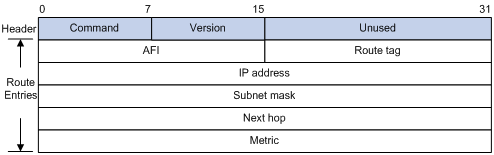
The differences from RIPv1 are stated as following.
l Version: Version of RIP. For RIPv2 the value is 0x02.
l Route Tag: Route Tag.
l IP Address: Destination IP address. It could be a natural network address, subnet address or host address.
l Subnet Mask: Mask of the destination address.
l Next Hop: If set to 0.0.0.0, it indicates that the originator of the route is the best next hop; otherwise it indicates a next hop better than the originator of the route.
RIPv2 authentication
RIPv2 sets the AFI field of the first route entry to 0xFFFF to identify authentication information. See Figure 2-3.
Figure 2-3 RIPv2 Authentication Message
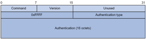
l Authentication Type: 2 represents plain text authentication, while 3 represents MD5.
l Authentication: Authentication data, including password information when plain text authentication is adopted or including key ID, MD5 authentication data length and sequence number when MD5 authentication is adopted.
![]()
l RFC 1723 only defines plain text authentication. For information about MD5 authentication, refer to RFC2082 “RIPv2 MD5 Authentication”.
l With RIPv1, you can configure the authentication mode in interface view. However, the configuration will not take effect because RIPv1 does not support authentication.
Supported RIP Features
The current implementation supports RIPv1 and RIPv2
Protocols and Standards
RFC 1058: Routing Information Protocol
RFC 1723: RIP Version 2 - Carrying Additional Information
RFC 1721: RIP Version 2 Protocol Analysis
RFC 1722: RIP Version 2 Protocol Applicability Statement
RFC 1724: RIP Version 2 MIB Extension
RFC 2082: RIPv2 MD5 Authentication
Configuring RIP Basic Functions
Configuration Prerequisites
Before configuring RIP basic functions, configure IP addresses for interfaces, making all adjacent nodes reachable to each other at the network layer.
Configuration Procedure
Enabling RIP and a RIP interface
Follow these steps to enable RIP:
|
Use the command… |
Remarks |
|
|
Enter system view |
system-view |
–– |
|
Enable a RIP process and enter RIP view |
rip [ process-id ] |
Required Not enabled by default |
|
Enable RIP on the interface attached to the specified network |
network network-address |
Required Disabled by default |
![]()
l If you make some RIP configurations in interface view before enabling RIP, those configurations will take effect after RIP is enabled.
l RIP runs only on the interfaces residing on the specified networks. Therefore, you need to specify the network after enabling RIP to validate RIP on a specific interface.
l You can enable RIP on all interfaces using the command network 0.0.0.0.
Configuring the interface behavior
Follow these steps to configure the interface behavior:
|
To do… |
Use the command… |
Remarks |
|
Enter system view |
system-view |
–– |
|
Enter RIP view |
rip [ process-id ] |
–– |
|
Disable an or all interfaces from sending routing updates (the interfaces can still receive updates) |
silent-interface { all | interface-type interface-number } |
Optional All interfaces can send routing updates by default. |
|
Return to system view |
quit |
— |
|
Enter interface view |
interface interface-type interface-number |
— |
|
Enable the interface to receive RIP messages |
rip input |
Optional Enabled by default |
|
Enable the interface to send RIP messages |
rip output |
Optional Enabled by default |
Configuring a RIP version
You can configure a RIP version in RIP or interface view.
l If neither global nor interface RIP version is configured, the interface sends RIPv1 broadcasts and can receive RIPv1 broadcast and unicast packets, and RIPv2 broadcast, multicast, and unicast packets.
l If an interface has no RIP version configured, it uses the global RIP version; otherwise it uses the RIP version configured on it.
l With RIPv1 configured, an interface sends RIPv1 broadcasts, and can receive RIPv1 broadcasts and RIPv1 unicasts.
l With RIPv2 configured, a multicast interface sends RIPv2 multicasts and can receive RIPv2 unicasts, broadcasts and multicasts.
l With RIPv2 configured, a broadcast interface sends RIPv2 broadcasts and can receive RIPv1 unicasts, and broadcasts, and RIPv2 broadcasts, multicasts and unicasts.
Follow these steps to configure a RIP version:
|
To do… |
Use the command… |
Remarks |
|
Enter system view |
system-view |
–– |
|
Enter RIP view |
rip [ process-id ] |
–– |
|
Specify a global RIP version |
version { 1 | 2 } |
Optional By default, if an interface has a RIP version specified, the version takes precedence over the global one. If no RIP version is specified for an interface, the interface can send RIPv1 broadcasts, and receive RIPv1 broadcasts, unicasts, RIPv2 broadcasts, multicasts and unicasts. |
|
Return to system view |
Quit |
— |
|
Enter interface view |
interface interface-type interface-number |
–– |
|
Specify a RIP version for the interface |
rip version { 1 | 2 [ broadcast | multicast ] } |
Optional |
Configuring RIP Route Control
In complex networks, you need to configure advanced RIP features.
This section covers the following topics:
l Configuring an Additional Routing Metric
l Configuring RIPv2 Route Summarization
l Disabling Host Route Reception
l Configuring Inbound/Outbound Route Filtering
l Configuring a Priority for RIP
l Configuring RIP Route Redistribution
Before configuring RIP routing feature, complete the following tasks:
l Configure an IP address for each interface, and make sure all neighboring routers are reachable to each other.
l Configure RIP basic functions
Configuring an Additional Routing Metric
An additional routing metric can be added to the metric of an inbound or outbound RIP route.
The outbound additional metric is added to the metric of a sent route, the route’s metric in the routing table is not changed.
The inbound additional metric is added to the metric of a received route before the route is added into the routing table, so the route’s metric is changed.
Follow these steps to configure additional routing metrics:
|
To do… |
Use the command… |
Remarks |
|
Enter system view |
system-view |
–– |
|
Enter interface view |
interface interface-type interface-number |
–– |
|
Define an inbound additional routing metric |
rip metricin value |
Optional 0 by default |
|
Define an outbound additional routing metric |
rip metricout value |
Optional 1 by default |
Configuring RIPv2 Route Summarization
Route summarization means that subnets in a natural network are summarized with a natural network that is sent to other networks. This feature can reduce the size of routing tables.
Enabling RIPv2 route automatic summarization
You can disable RIPv2 route automatic summarization if you want to advertise all subnet routes.
Follow these steps to enable RIPv2 route automatic summarization:
|
Use the command… |
Remarks |
|
|
Enter system view |
system-view |
–– |
|
Enter RIP view |
rip [ process-id ] |
–– |
|
Enable RIPv2 automatic route summarization |
summary |
Optional Enabled by default |
Advertising a summary route
You can configure RIPv2 to advertise a summary route on the specified interface.
To do so, use the following commands:
|
To do… |
Use the command… |
Remarks |
|
Enter system view |
system-view |
–– |
|
Enter RIP view |
rip [ process-id ] |
–– |
|
Disable RIPv2 automatic route summarization |
undo summary |
Required Enabled by default |
|
Return to system view |
quit |
— |
|
Enter interface view |
interface interface-type interface-number |
— |
|
Advertise a summary route |
rip summary-address ip-address { mask | mask-length } |
Required |
![]()
You need to disable RIPv2 route automatic summarization before advertising a summary route on an interface.
Disabling Host Route Reception
Sometimes a router may receive many host routes from the same network, which are not helpful for routing and occupy a large amount of network resources. In this case, you can disable RIP from receiving host routes to save network resources.
Follow these steps to disable RIP from receiving host routes:
|
To do… |
Use the command… |
Remarks |
|
Enter system view |
system-view |
— |
|
Enter RIP view |
rip [ process-id ] |
— |
|
Disable RIP from receiving host routes |
undo host-route |
Required Enabled by default |
![]()
RIPv2 can be disabled from receiving host routes, but RIPv1 cannot.
Advertising a Default Route
You can configure RIP to advertise a default route with A specified metric to RIP neighbors.
Follow these steps to configure RIP to advertise a default route:
|
To do… |
Use the command… |
Remarks |
|
Enter system view |
system-view |
–– |
|
Enter RIP view |
rip [ process-id ] |
–– |
|
Enable RIP to advertise a default route |
default-route originate cost value |
Required Not enabled by default |
![]()
The router enabled to advertise a default route does not receive default routes from RIP neighbors.
Configuring Inbound/Outbound Route Filtering
The device supports route filtering. You can filter routes by configuring the inbound and outbound route filtering policies via referencing an ACL or IP prefix list. You can also configure the router to receive only routes from a specified neighbor.
Follow these steps to configure route filtering:
|
To do… |
Use the command… |
Remarks |
|
Enter system view |
system-view |
–– |
|
Enter RIP view |
rip [ process-id ] |
–– |
|
Configure the filtering of incoming routes |
filter-policy { acl-number | gateway ip-prefix-name | ip-prefix ip-prefix-name [ gateway ip-prefix-name ] } import [ interface-type interface-number ] |
Required Not configured by default |
|
Configure the filtering of outgoing routes |
filter-policy { acl-number | ip-prefix ip-prefix-name } export [ protocol [ process-id ] | interface-type interface-number ] |
Required Not configured by default |
![]()
l Using the filter-policy import command filters incoming routes. Routes not passing the filtering will be neither installed into the routing table nor advertised to neighbors.
l Using the filter-policy export command filters outgoing routes, including routes redistributed with the import-route command.
Configuring a Priority for RIP
Multiple IGP protocols may run in a router. If you want RIP routes to have a higher priority than those learned by other routing protocols, you can assign RIP a smaller priority value to influence optimal route selection.
Follow these steps to configure a priority for RIP:
|
To do… |
Use the command… |
Remarks |
|
Enter system view |
system-view |
–– |
|
Enter RIP view |
rip [ process-id ] |
–– |
|
Configure a priority for RIP |
preference value |
Optional 100 by default |
Configuring RIP Route Redistribution
Follow these steps to configure RIP route redistribution:
|
To do… |
Use the command… |
Remarks |
|
Enter system view |
system-view |
–– |
|
Enter RIP view |
rip [ process-id ] |
–– |
|
Configure a default metric for redistributed routes |
default-cost value |
Optional The default metric of a redistributed route is 0 by default. |
|
Redistribute routes from another protocol |
import-route protocol [ cost cost | tag tag ] * |
Required No redistribution is configured by default. |
Configuring RIP Network Optimization
Complete the following tasks before configuring RIP network optimization:
l Configure network addresses for interfaces, and make neighboring nodes reachable to each other;
l Configure RIP basic functions.
Configuring RIP Timers
Follow these steps to configure RIP timers:
|
To do… |
Use the command… |
Remarks |
|
Enter system view |
system-view |
–– |
|
Enter RIP view |
rip [ process-id ] |
–– |
|
Configure values for RIP timers |
timers { garbage-collect garbage-collect-value | suppress suppress-value | timeout timeout-value | update update-value }* |
Optional The default update timer, timeout timer, suppress timer, and garbage-collect timer are 30s, 180s, 120s and 120s respectively. |
![]()
Based on network performance, you need to make RIP timers of RIP routers identical to each other to avoid unnecessary traffic or route oscillation.
Configuring Split Horizon and Poison Reverse
![]()
If both split horizon and poison reverse are configured, only the poison reverse function takes effect.
Enabling split horizon
The split horizon function disables an interface from sending routes received from the interface to prevent routing loops between adjacent routers.
Follow these steps to enable split horizon:
|
To do… |
Use the command… |
Remarks |
|
Enter system view |
system-view |
— |
|
Enter interface view |
interface interface-type interface-number |
— |
|
Enable split horizon |
rip split-horizon |
Optional Enabled by default |
![]()
Disabling the split horizon function on a point-to-point link does not take effect.
Enabling poison reverse
The poison reverse function allows an interface to advertise the routes received from it, but the metric of these routes is set to 16, making them unreachable.
Follow these steps to enable poison reverse:
|
To do… |
Use the command… |
Remarks |
|
Enter system view |
system-view |
— |
|
Enter interface view |
interface interface-type interface-number |
— |
|
Enable poison reverse |
rip poison-reverse |
Required Disabled by default |
Enabling Zero Field Check on Incoming RIPv1 Messages
Some fields in the RIPv1 message must be zero. These fields are called zero fields. You can enable zero field check on received RIPv1 messages. If such a field contains a non-zero value, the RIPv1 message will not be processed. If you are sure that all messages are trusty, you can disable zero field check to save CPU resources.
Follow these steps to enable zero field check on incoming RIPv1 messages:
|
To do… |
Use the command… |
Remarks |
|
Enter system view |
system-view |
–– |
|
Enter RIP view |
rip [ process-id ] |
–– |
|
Enable zero field check on received RIPv1 messages |
checkzero |
Optional Enabled by default |
Enabling Source IP Address Check on Incoming RIP Updates
You can enable source IP address check on incoming RIP updates.
For a message received on an Ethernet interface, RIP compares the source IP address of the message with the IP address of the interface. If they are not in the same network segment, RIP discards the message.
For a message received on a serial interface, RIP checks whether the source address of the message is the IP address of the peer interface. If not, RIP discards the message.
Follow these steps to enable source IP address check on incoming RIP updates:
|
To do… |
Use the command… |
Remarks |
|
Enter system view |
system-view |
–– |
|
Enter RIP view |
rip [ process-id ] |
–– |
|
Enable source IP address check on incoming RIP messages |
validate-source-address |
Optional Enabled by default |
![]()
The source IP address check feature should be disabled if a RIP neighbor is not directly connected.
Configuring RIPv2 Message Authentication
RIPv2 supports two authentication modes: plain text and MD5.
In plain text authentication, the authentication information is sent with the RIP message, which however cannot meet high security needs.
Follow these steps to configure RIPv2 message authentication:
|
To do… |
Use the command… |
Remarks |
|
Enter system view |
system-view |
–– |
|
Enter interface view |
interface interface-type interface-number |
–– |
|
Configure RIPv2 authentication |
rip authentication-mode { md5 { rfc2082 key-string key-id | rfc2453 key-string } | simple password } |
Required |
Specifying a RIP Neighbor
Usually, RIP sends messages to broadcast or multicast addresses. On non broadcast or multicast links, you need to manually specify RIP neighbors. If a specified neighbor is not directly connected, you must disable source address check on incoming updates.
Follow these steps to specify a RIP neighbor:
|
To do… |
Use the command… |
Remarks |
|
Enter system view |
system-view |
–– |
|
Enter RIP view |
rip [ process-id ] |
–– |
|
Specify a RIP neighbor |
peer ip-address |
Required By default, RIP sends no updates to any IP address. |
|
Disable source address check on incoming RIP updates |
undo validate-source-address |
Required Not disabled by default |
![]()
You need not use the peer ip-address command when the neighbor is directly connected; otherwise the neighbor may receive both the unicast and multicast (or broadcast) of the same routing information.
Displaying and Maintaining RIP
|
Use the command… |
Remarks |
|
|
Display RIP current status and configuration information |
display rip [ process-id ] |
Available in any view |
|
Display all active routes in RIP database |
display rip process-id database |
|
|
Display RIP interface information |
display rip process-id interface [ interface-type interface-number ] |
|
|
Display routing information about a specified RIP process |
display rip process-id route [ statistics | ip-address { mask | mask-length } | peer ip-address ] |
|
|
Clear the statistics of a RIP process |
reset rip process-id statistics |
Available in user view |
RIP Configuration Examples
Configuring RIP Version
Network requirements
As shown in Figure 2-4, enable RIPv2 on all interfaces on AC and Switch.
Network diagram
Figure 2-4 Network diagram for RIP version configuration
Configuration procedure
1) Configure IP addresses for interfaces (omitted).
2) Configure basic RIP functions
# Configure AC.
<AC> system-view
<AC> system-view
[AC] rip
[AC-rip-1] network 192.168.1.0
[AC-rip-1] network 172.16.0.0
[AC-rip-1] network 172.17.0.0
[AC-rip-1] quit
# Configure Switch.
<Switch> system-view
[Switch] rip
[Switch-rip-1] network 192.168.1.0
[Switch-rip-1] network 10.0.0.0
[Switch-rip-1] quit
# Display the RIP routing table of AC.
[AC] display rip 1 route
Route Flags: R - RIP, T - TRIP
P - Permanent, A - Aging, S - Suppressed, G - Garbage-collect
-------------------------------------------------------------------------
Peer 192.168.1.2 on Vlan-interface100
Destination/Mask Nexthop Cost Tag Flags Sec
10.0.0.0/8 192.168.1.2 1 0 RA 11
From the routing table, you can find RIPv1 uses natural mask.
3) Configure RIP version
# Configure RIPv2 on AC.
[AC] rip
[AC-rip-1] version 2
[AC-rip-1] undo summary
# Configure RIPv2 on Switch.
[Switch] rip
[Switch-rip-1] version 2
[Switch-rip-1] undo summary
# Display the RIP routing table on AC.
[AC] display rip 1 route
Route Flags: R - RIP, T - TRIP
P - Permanent, A - Aging, S - Suppressed, G - Garbage-collect
--------------------------------------------------------------------------
Peer 192.168.1.2 on Vlan-interface100
Destination/Mask Nexthop Cost Tag Flags Sec
10.2.1.0/24 192.168.1.2 1 0 RA 16
10.1.1.0/24 192.168.1.2 1 0 RA 16
From the routing table, you can see RIPv2 uses classless subnet masks.
![]()
Since RIPv1 routing information has a long aging time, it will still exist until aged out after RIPv2 is configured.
Troubleshooting RIP
No RIP Updates Received
Symptom:
No RIP updates are received when the links work well.
Analysis:
After enabling RIP, you must use the network command to enable corresponding interfaces. Make sure no interfaces are disabled from handling RIP messages.
If the peer is configured to send multicast messages, the same should be configured on the local end.
Solution:
l Use the display current-configuration command to check RIP configuration
l Use the display rip command to check whether some interface is disabled
Route Oscillation Occurred
Symptom:
When all links work well, route oscillation occurs on the RIP network. After displaying the routing table, you may find some routes appear and disappear in the routing table intermittently.
Analysis:
In the RIP network, make sure all the same timers within the whole network are identical and relationships between timers are reasonable. For example, the timeout timer value should be larger than the update timer value.
Solution:
l Use the display rip command to check the configuration of RIP timers
l Use the timers command to adjust timers properly.
![]()
l The term “router” in this document refers to a router in a generic sense or a Layer 3 switch.
l The WX6103 access controller switch interface board supports only static routing, RIP, and OSPF routing protocols.
l The WX6103 access controller switch interface board supports only Ethernet link layer protocols. Therefore, the OSPF interface type can only be broadcast because other types are not supported.
Open Shortest Path First (OSPF) is a link state interior gateway protocol developed by the OSPF working group of the Internet Engineering Task Force (IETF). At present, OSPF version 2 (RFC2328) is used.
When configuring OSPF, go to these sections for information you are interested in:
l OSPF Configuration Task List
l Configuring OSPF Basic Functions
l Configuring OSPF Area Parameters
l Configuring OSPF Route Control
l Configuring OSPF Network Optimization
l Configuring OSPF Graceful Restart
l Displaying and Maintaining OSPF
l Troubleshooting OSPF Configuration
Introduction to OSPF
![]()
Unless otherwise noted, OSPF refers to OSPFv2 throughout this document.
OSPF has the following features:
l Wide scope: Supports networks of various sizes and up to several hundred routers in an OSPF routing domain.
l Fast convergence: Transmits updates instantly after network topology changes for routing information synchronization in the AS.
l Loop-free: Computes routes with the shortest path first (SPF) algorithm according to the collected link states, so no route loops are generated.
l Area partition: Allows an AS to be split into different areas for ease of management and the routing information transmitted between areas is summarized to reduce network bandwidth consumption.
l Equal-cost multi-route: Supports multiple equal-cost routes to a destination.
l Routing hierarchy: Supports a four-level routing hierarchy that prioritizes the routes into intra-area, inter-area, external Type-1, and external Type-2 routes.
l Authentication: Supports interface-based packet authentication to guarantee the security of packet exchange.
l Multicast: Supports packet multicasting on some types of links.
Basic Concepts
Autonomous System
A set of routers using the same routing protocol to exchange routing information constitute an Autonomous System (AS).
OSPF route computation
OSPF route computation is described as follows:
l Based on the network topology around itself, each router generates Link State Advertisements (LSA) and sends them to other routers in update packets.
l Each OSPF router collects LSAs from other routers to compose a LSDB (Link State Database). An LSA describes the network topology around a router, so the LSDB describes the entire network topology of the AS.
l Each router transforms the LSDB to a weighted directed graph, which actually reflects the topology architecture of the entire network. All the routers have the same graph.
l Each router uses the SPF algorithm to compute a Shortest Path Tree that shows the routes to the nodes in the autonomous system. The router itself is the root of the tree.
Router ID
To run OSPF, a router must have a Router ID, which is a 32-bit unsigned integer, the unique identifier of the router in the AS.
You may assign a Router ID to an OSPF router manually. If no Router ID is specified, the system automatically selects one for the router as follows:
l If the loopback interfaces are configured, select the highest IP address among them.
l If no loopback interface is configured, select the highest IP address among addresses of active interfaces on the router.
OSPF packets
OSPF uses five types of packets:
l Hello packet: Periodically sent to find and maintain neighbors, containing the values of some timers, information about the DR, BDR and known neighbors.
l DD packet (database description packet): Describes the digest of each LSA in the LSDB, exchanged between two routers for data synchronization.
l LSR (link state request) packet: Requests needed LSAs from the neighbor. After exchanging the DD packets, the two routers know which LSAs of the neighbor are missing from the local LSDBs. In this case, they send an LSR packet to each other, requesting the missing LSAs. The LSA packet contains the digest of the missing LSAs.
l LSU (link state update) packet: Transmits the needed LSAs to the neighbor.
l LSAck (link state acknowledgment) packet: Acknowledges received LSU packets. It contains the headers of received LSAs (a packet can acknowledge multiple LSAs).
LSA types
OSPF sends routing information in LSAs, which, as defined in RFC 2328, have the following types:
l Router LSA: Type-1 LSA, originated by all routers, flooded throughout a single area only. This LSA describes the collected states of the router's interfaces to an area.
l Network LSA: Type-2 LSA, originated for broadcast and NBMA networks by the designated router, flooded throughout a single area only. This LSA contains the list of routers connected to the network.
l Network Summary LSA: Type-3 LSA, originated by ABRs (Area Border Routers), and flooded throughout the LSA's associated area. Each summary-LSA describes a route to a destination outside the area, yet still inside the AS (an inter-area route).
l ASBR Summary LSA: Type-4 LSA, originated by ABRs and flooded throughout the LSA's associated area. Type 4 summary-LSAs describe routes to ASBR (Autonomous System Boundary Router).
l AS External LSA: Type-5 LSA, by ASBRs, and flooded throughout the AS (except stub and NSSA areas). Each AS-external-LSA describes a route to another AS.
l NSSA External LSA: Type-7 LSA, as defined in RFC 1587, originated by ASBRs in NSSAs (Not-So-Stubby Areas) and flooded throughout a single NSSA. NSSA LSAs describe routes to other ASs.
l Opaque LSA: A proposed type of LSA, the format of which consists of a standard LSA header and application specific information. Opaque LSAs are used by the OSPF protocol or by some application to distribute information into the OSPF routing domain. The opaque LSA includes three types, Type 9, Type 10 and Type 11, which are used to flood into different areas. The Type 9 opaque LSA is flooded into the local subnet, the Type 10 is flooded into the local area, and the Type 11 is flooded throughout the whole AS.
Neighbor and Adjacency
In OSPF, the “Neighbor” and “Adjacency” are two different concepts.
Neighbor: Two routers that have interfaces to a common network. Neighbor relationships are maintained by, and usually dynamically discovered by, OSPF's hello packets. When a router starts, it sends a hello packet via the OSPF interface, and the router that receives the hello packet checks parameters carried in the packet. If parameters of the two routers match, they become neighbors.
Adjacency: A relationship formed between selected neighboring routers for the purpose of exchanging routing information. Not every pair of neighboring routers become adjacent, which depends on network types. Only by synchronizing the LSDB via exchanging DD packets and LSAs can two routers become adjacent.
OSPF Area Partition and Route Summarization
Area partition
When a large number of OSPF routers are present on a network, LSDBs may become so large that a great amount of storage space is occupied and CPU resources are exhausted by performing SPF computation.
In addition, as the topology of a large network is prone to changes, enormous OSPF packets may be created, reducing bandwidth utilization. Each topology change makes all routers perform route calculation.
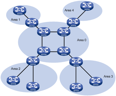
To solve this problem, OSPF splits an AS into multiple areas, which are identified by area ID. The boundaries between areas are routers rather than links. A network segment (or a link) can only reside in one area, in other words, an OSPF interface must be specified to belong to its attached area, as shown in the figure below.
Figure 3-1 OSPF area partition
After area partition, area border routers perform route summarization to reduce the number of LSAs advertised to other areas and minimize the effect of topology changes.
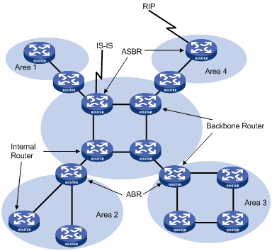
Classification of Routers
The OSPF routers fall into four types according to the position in the AS:
1) Internal Router
All interfaces on an internal router belong to one OSPF area.
2) Area Border Router (ABR)
An area border router belongs to more than two areas, one of which must be the backbone area. It connects the backbone area to a non-backbone area. The connection between an area border router and the backbone area can be physical or logical.
3) Backbone Router
At least one interface of a backbone router must be attached to the backbone area. Therefore, all ABRs and internal routers in area 0 are backbone routers.
4) Autonomous System Border Router (ASBR)
The router exchanging routing information with another AS is an ASBR, which may not reside on the boundary of the AS. It can be an internal router or area border router.
Figure 3-2 OSPF router types
Backbone area and virtual links
Each AS has a backbone area, which is responsible for distributing routing information between none-backbone areas. Routing information between non-backbone areas must be forwarded by the backbone area. Therefore, OSPF requires that:
l All non-backbone areas must maintain connectivity to the backbone area.
l The backbone area itself must maintain connectivity.
In practice, due to physical limitations, the requirements may not be satisfied. In this case, configuring OSPF virtual links is a solution.
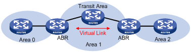
A virtual link is established between two area border routers via a non-backbone area and is configured on both ABRs to take effect. The area that provides the non-backbone area internal route for the virtual link is a “transit area”.
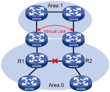
In the following figure, Area 2 has no direct physical link to the backbone area 0. Configuring a virtual link between ABRs can connect Area 2 to the backbone area.
Figure 3-3 Virtual link application 1
Another application of virtual links is to provide redundant links. If the backbone area cannot maintain internal connectivity due to a physical link failure, configuring a virtual link can guarantee logical connectivity in the backbone area, as shown below.
Figure 3-4 Virtual link application 2
The virtual link between the two ABRs acts as a point-to-point connection. Therefore, you can configure interface parameters such as hello packet interval on the virtual link as they are configured on physical interfaces.
The two ABRs on the virtual link exchange OSPF packets with each other directly, and the OSPF routers in between simply convey these OSPF packets as normal IP packets.
(Totally) Stub area
The ABR in a stub area does not distribute Type-5 LSAs into the area, so the routing table size and amount of routing information in this area are reduced significantly.
You can configure the stub area as a totally stub area, where the ABR advertises neither the destinations in other areas nor the external routes.
Stub area configuration is optional, and not every area is eligible to be a stub area. In general, a stub area resides on the border of the AS.
The ABR in a stub area generates a default route into the area.
Note the following when configuring a (totally) stub area:
l The backbone area cannot be a (totally) stub area.
l The stub command must be configured on routers in a (totally) stub area.
l A (totally) stub area cannot have an ASBR because AS external routes cannot be distributed into the stub area.
l Virtual links cannot transit (totally) stub areas.
NSSA area
Similar to a stub area, an NSSA area imports no AS external LSA (Type-5 LSA) but can import Type-7 LSAs that are generated by the ASBR and distributed throughout the NSSA area. When traveling to the NSSA ABR, Type-7 LSAs are translated into Type-5 LSAs by the ABR for advertisement to other areas.
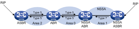
In the following figure, the OSPF AS contains three areas: Area 1, Area 2 and Area 0. The other two ASs employ the RIP protocol. Area 1 is an NSSA area, and the ASBR in it translates RIP routes into Type-7 LSAs and advertises them throughout Area 1. When these LSAs travel to the NSSA ABR, the ABR translates Type-7 LSAs to Type-5 LSAs for advertisement to Area 0 and Area 2.
On the left of the figure, RIP routes are translated into Type-5 LSAs by the ASBR of Area 2 and distributed into the OSPF AS. However, Area 1 is an NSSA area, so these Type-5 LSAs cannot travel to Area 1.
Like stub areas, virtual links cannot transit NSSA areas.
Figure 3-5 NSSA area
Route summarization
Route summarization: An ABR or ASBR summarizes routes with the same prefix with a single route and distribute it to other areas.
Via route summarization, routing information across areas and the size of routing tables on routers will be reduced, improving calculation speed of routers.
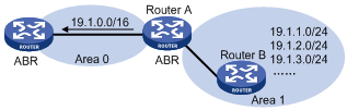
For example, as shown in the following figure, in Area 1 are three internal routes 19.1.1.0/24, 19.1.2.0/24, and 19.1.3.0/24. By configuring route summarization on Router A, the three routes are summarized with the route 19.1.0.0/16 that is advertised into Area 0.
Figure 3-6 Route summarization
OSPF has two types of route summarization:
1) ABR route summarization
To distribute routing information to other areas, an ABR generates Type-3 LSAs on a per network segment basis for an attached non-backbone area. If contiguous network segments are available in the area, you can summarize them with a single network segment. The ABR in the area distributes only the summary LSA to reduce the scale of LSDBs on routers in other areas.
2) ASBR route summarization
If summarization for redistributed routes is configured on an ASBR, it will summarize redistributed Type-5 LSAs that fall into the specified address range. If in an NSSA area, it also summarizes Type-7 LSAs that fall into the specified address range.
If this feature is configured on an ABR, the ABR will summarize Type-5 LSAs translated from Type-7 LSAs.
Route types
OSPF prioritize routes into four levels:
l Intra-area route
l Inter-area route
l Type-1 external route
l Type-2 external route
The intra-area and inter-area routes describe the network topology of the AS, while external routes describe routes to destinations outside the AS.
OSPF classifies external routes into two types: Type-1 and Type-2. A Type-1 external route is an IGP route, such as a RIP or static route, which has high credibility and whose cost is comparable with the cost of an OSPF internal route. The cost from a router to the destination of the Type-1 external route= the cost from the router to the corresponding ASBR+ the cost from the ASBR to the destination of the external route.
A Type-2 external route is an EGP route, which has low credibility, so OSPF considers the cost from the ASBR to the destination of the Type-2 external route is much bigger than the cost from the ASBR to an OSPF internal router. Therefore, the cost from the internal router to the destination of the Type-2 external route= the cost from the ASBR to the destination of the Type-2 external route. If two routes to the same destination have the same cost, then take the cost from the router to the ASBR into consideration.
Classification of OSPF Networks
OSPF network types
OSPF classifies networks into four types upon the link layer protocol:
l Broadcast: When the link layer protocol is Ethernet or FDDI, OSPF considers the network type broadcast by default. On Broadcast networks, packets are sent to multicast addresses (such as 224.0.0.5 and 224.0.0.6).
l NBMA (Non-Broadcast Multi-Access): When the link layer protocol is Frame Relay, ATM or X.25, OSPF considers the network type as NBMA by default. Packets on these networks are sent to unicast addresses.
l P2MP (point-to-multipoint): By default, OSPF considers no link layer protocol as P2MP, which is a conversion from other network types such as NBMA in general. On P2MP networks, packets are sent to multicast addresses (224.0.0.5).
l P2P (point-to-point): When the link layer protocol is PPP or HDLC, OSPF considers the network type as P2P. On P2P networks, packets are sent to multicast addresses (224.0.0.5).
NBMA network configuration principle
Typical NBMA networks are ATM and Frame Relay networks.
You need to perform some special configuration on NBMA interfaces. Since these interfaces cannot broadcast hello packets for neighbor location, you need to specify neighbors manually and configure whether the neighbors have the DR election right.
An NBMA network is fully meshed, which means any two routers in the NBMA network have a direct virtual link for communication. If direct connections are not available between some routers, the type of interfaces associated should be configured as P2MP, or as P2P for interfaces with only one neighbor.
Differences between NBMA and P2MP networks:
l NBMA networks are fully meshed, non-broadcast and multi access. P2MP networks are not required to be fully meshed.
l It is required to elect the DR and BDR on NBMA networks, while DR and BDR are not available on P2MP networks.
l NBMA is the default network type, while P2MP is a conversion from other network types, such as NBMA in general.
l On NBMA networks, packets are unicast, and neighbors are configured manually on routers. On P2MP networks, packets are multicast.
DR and BDR
DR/BDR introduction
On broadcast or NBMA networks, any two routers exchange routing information with each other. If n routers are present on a network, n(n-1)/2 adjacencies are required. Any change on a router in the network generates traffic for routing information synchronization, consuming network resources. The Designated Router is defined to solve the problem. All other routers on the network send routing information to the DR, which is responsible for advertising link state information.
If the DR fails to work, routers on the network have to elect another DR and synchronize information with the new DR. It is time-consuming and prone to routing calculation errors. The Backup Designated Router (BDR) is introduced to reduce the synchronization period.
The BDR is elected along with the DR and establishes adjacencies for routing information exchange with all other routers. When the DR fails, the BDR will become the new DR in a very short period by avoiding adjacency establishment and DR reelection. Meanwhile, other routers elect another BDR, which requires a relatively long period but has no influence on routing calculation.
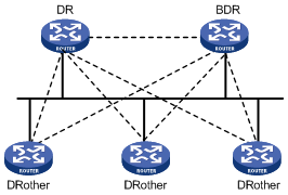
Other routers, also known as DRothers, establish no adjacency and exchange no routing information with each other, thus reducing the number of adjacencies on broadcast and NBMA networks.
In the following figure, real lines are Ethernet physical links, and dashed lines represent adjacencies. With the DR and BDR in the network, only seven adjacencies are enough.
Figure 3-7 DR and BDR in a network
DR/BDR election
The DR and BDR in a network are elected by all routers rather than configured manually. The DR priority of an interface determines its qualification for DR/BDR election. Interfaces attached to the network and having priorities higher than ‘0” are election candidates.
The election votes are hello packets. Each router sends the DR elected by itself in a hello packet to all the other routers. If two routers on the network declare themselves as the DR, the router with the higher DR priority wins. If DR priorities are the same, the router with the higher router ID wins. In addition, a router with the priority 0 cannot become the DR/BDR.
Note that:
l The DR election is available on broadcast, NBMA interfaces rather than P2P, or P2MP interfaces.
l A DR is an interface of a router and belongs to a single network segment. The router’s other interfaces may be a BDR or DRother.
l After DR/BDR election and then a new router joins, it cannot become the DR immediately even if it has the highest priority on the network.
l The DR may not be the router with the highest priority in a network, and the BDR may not be the router with the second highest priority.
OSPF Packet Formats
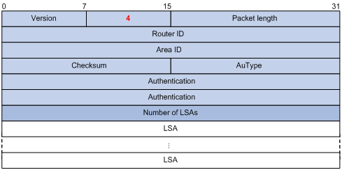
OSPF packets are directly encapsulated into IP packets. OSPF has the IP protocol number 89. The OSPF packet format is shown below (taking a LSU packet as an example).
Figure 3-8 OSPF packet format
![]()
OSPF packet header
OSPF packets are classified into five types that have the same packet header, as shown below.
Figure 3-9 OSPF packet header
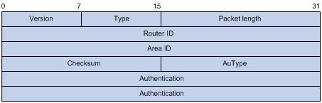
l Version: OSPF version number, which is 2 for OSPFv2.
l Type: OSPF packet type from 1 to 5, corresponding with hello, DD, LSR, LSU and LSAck respectively.
l Packet length: Total length of the OSPF packet in bytes, including the header.
l Router ID: ID of the advertising router.
l Area ID: ID of the area where the advertising router resides.
l Checksum: Checksum of the message.
l Autype: Authentication type from 0 to 2, corresponding with non-authentication, simple (plaintext) authentication and MD5 authentication respectively.
l Authentication: Information determined by authentication type. It is not defined for authentication type 0. It is defined as password information for authentication type 1, and defined as Key ID, MD5 authentication data length and sequence number for authentication type 2.
![]()
MD5 authentication data is added following an OSPF packet rather than contained in the Authentication field.
Hello packet
A router sends hello packets periodically to neighbors to find and maintain neighbor relationships and to elect the DR/BDR, including information about values of timers, DR, BDR and neighbors already known. The format is shown below:
Figure 3-10 Hello packet format
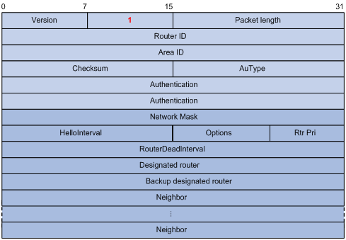
Major fields:
l Network Mask: Network mask associated with the router’s sending interface. If two routers have different network masks, they cannot become neighbors.
l HelloInterval: Interval for sending hello packets. If two routers have different intervals, they cannot become neighbors.
l Rtr Pri: Router priority. A value of 0 means the router cannot become the DR/BDR.
l RouterDeadInterval: Time before declaring a silent router down. If two routers have different time values, they cannot become neighbors.
l Designated Router: IP address of the DR interface.
l Backup Designated Router: IP address of the BDR interface
l Neighbor: Router ID of the neighbor router.
DD packet
Two routers exchange database description (DD) packets describing their LSDBs for database synchronization, contents in DD packets including the header of each LSA (uniquely representing a LSA). The LSA header occupies small part of an LSA to reduce traffic between routers. The recipient checks whether the LSA is available using the LSA header.
The DD packet format:
Figure 3-11 DD packet format
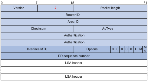
Major fields:
l Interface MTU: Size in bytes of the largest IP datagram that can be sent out the associated interface, without fragmentation.
l I (Initial) The Init bit, which is set to 1 if the packet is the first packet of database description packets, and set to 0 if not.
l M (More): The More bit, which is set to 0 if the packet is the last packet of DD packets, and set to 1 if more DD Packets are to follow.
l MS (Master/Slave): The Master/Slave bit. When set to 1, it indicates that the router is the master during the database exchange process. Otherwise, the router is the slave.
l DD Sequence Number: Used to sequence the collection of database description packets for ensuring reliability and intactness of DD packets between the master and slave. The initial value is set by the master. The DD sequence number then increments until the complete database description has been sent.
LSR packet
After exchanging DD packets, any two routers know which LSAs of the peer routers are missing from the local LSDBs. In this case, they send LSR (link state request) packets, requesting the missing LSAs. The packets contain the digests of the missing LSAs. The following figure shows the LSR packet format.
Figure 3-12 LSR packet format
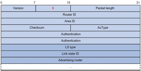
Major fields:
l LS type: Type number of the LSA to be requested. Type 1 for example indicates the Router LSA.
l Link State ID: Determined by LSA type.
l Advertising Router: ID of the router that sent the LSA.
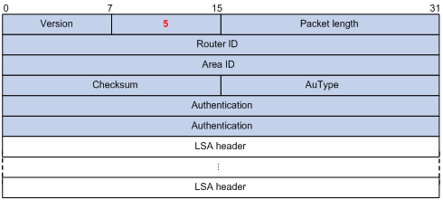
LSU packet
LSU (Link State Update) packets are used to send the requested LSAs to peers, and each packet carries a collection of LSAs. The LSU packet format is shown below.
Figure 3-13 LSU packet format
LSAck packet
LSAack (Link State Acknowledgment) packets are used to acknowledge received LSU packets, contents including LSA headers to describe the corresponding LSAs. Multiple LSAs can be acknowledged in a single Link State Acknowledgment packet. The following figure gives its format.
Figure 3-14 LSAck packet format
LSA header format
All LSAs have the same header, as shown in the following figure.
Figure 3-15 LSA header format
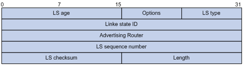
Major fields:
l LS age: Time in seconds elapsed since the LSA was originated. A LSA ages in the LSDB (added by 1 per second), but does not in transmission.
l LS type: Type of the LSA.
l Link State ID: The contents of this field depend on the LSA's type
l LS sequence number: Used by other routers to judge new and old LSAs.
l LS checksum: Checksum of the LSA except the LS age field.
l Length: Length in bytes of the LSA, including the LSA header.
Formats of LSAs
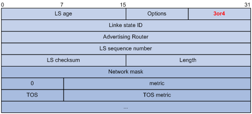
1) Router LSA
Figure 3-16 Router LSA format
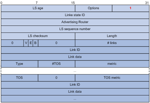
Major fields:
l Link State ID: ID of the router that originated the LSA.
l V (Virtual Link): Set to 1 if the router that originated the LSA is a virtual link endpoint.
l E (External): Set to 1 if the router that originated the LSA is an ASBR.
l B (Border): Set to 1 if the router that originated the LSA is an ABR.
l # links: Number of router links (interfaces) to the area, described in the LSA.
l Link ID: Determined by Link type.
l Link Data: Determined by Link type.
l Type: Link type. A value of 1 indicates a point-to-point link to a remote router; a value of 2 indicates a link to a transit network; a value of 3 indicates a link to a stub network; a value of 4 indicates a virtual link.
l #TOS: Number of different TOS metrics given for this link.
l metric: Cost of using this router link.
l TOS: IP Type of Service that this metric refers to.
l TOS metric: TOS-specific metric information.
2) Network LSA
A Network LSA is originated by the DR on a broadcast or NBMA network. The LSA describes all routers attached to the network.
Figure 3-17 Network LSA format
Major fields:
l Link State ID: The interface address of the DR
l Network Mask: The mask of the network (a broadcast or NBMA network)
l Attached Router: The IDs of the routers, which are adjacent to the DR, including the DR itself
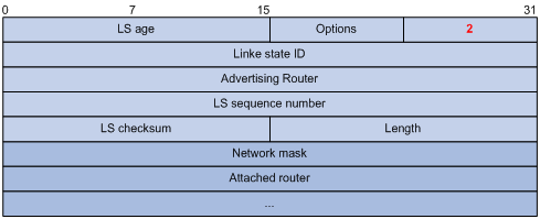
3) Summary LSA
Network summary LSAs (Type-3 LSAs) and ASBR summary LSAs (Type-4 LSAs) are originated by ABRs. Other than the difference in the Link State ID field, the format of type 3 and 4 summary-LSAs is identical.
Figure 3-18 Summary LSA format
Major fields:
l Link State ID: For a Type-3 LSA, it is an IP address outside the area; for a type 4 LSA, it is the router ID of an ASBR outside the area.
l Network Mask: The network mask for the type 3 LSA; set to 0.0.0.0 for the Type-4 LSA
l metric: The metric to the destination
![]()
A Type-3 LSA can be used to advertise a default route, having the Link State ID and Network Mask set to 0.0.0.0.
4) AS external LSA
An AS external LSA originates from an ASBR, describing routing information to a destination outside the AS.
Figure 3-19 AS external LSA format
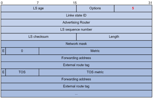
Major fields:
l Link State ID: The IP address of another AS to be advertised. When describing a default route, the Link State ID is always set to Default Destination (0.0.0.0) and the Network Mask is set to 0.0.0.0
l Network Mask: The IP address mask for the advertised destination
l E (External Metric): The type of the external metric value, which is set to 1 for type 2 external routes, and set to 0 for type 1 external routes. Refer to Route types for description about external route types
l metric: The metric to the destination
l Forwarding Address: Data traffic for the advertised destination will be forwarded to this address
l External Route Tag: A tag attached to each external route. This is not used by the OSPF protocol itself. It may be used to manage external routes.
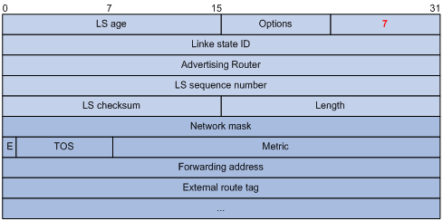
5) NSSA external LSA
An NSSA external LSA originates from the ASBR in a NSSA and is flooded in the NSSA area only. It has the same format as the AS external LSA.
Figure 3-20 NSSA external LSA format
Supported OSPF Features
Multi-process
With multi-process support, multiple OSPF processes can run on a router simultaneously and independently. Routing information interactions between different processes seem like interactions between different routing protocols. Multiple OSPF processes can use the same RID.
An interface of a router can only belong to a single OSPF process.
Authentication
OSPF supports authentication on packets. Only packets that pass the authentication are received. If hello packets cannot pass authentication, no neighbor relationship can be established.
The authentication type for interfaces attached to a single area must be identical. Authentication types include non-authentication, plaintext authentication and MD5 ciphertext authentication. The authentication password for interfaces attached to a network segment must be identical.
OSPF Graceful Restart
![]()
For GR information, refer to IP Routing-GR Overview.
After an OSPF GR Restarter restarts OSPF, it needs to perform the following two tasks in order to re-synchronize its LSDB with its neighbors.
l To obtain once again effective OSPF neighbor information, supposing the adjacencies are not changed.
l To obtain once again LSDB contents.
Before the restart, the GR Restarter originates Grace-LSAs to negotiate the GR capability. During the restart, the GR Helpers continue to advertise their adjacencies with the GR Restarter.
After the restart, the GR Restarter will send an OSPF GR signal to its neighbors that will not reset their adjacencies with it. In this way, the GR Restarter can restore the neighbor table upon receiving the responses from neighbors.
After reestablishing neighbor relationships, the GR Restarter will synchronize the LSDB and exchange routing information with all adjacent GR-capable neighbors. After that, the GR Restarter will update its own routing table and forwarding table based on the new routing information and remove the stale routes. In this way, the OSPF routing convergence is complete.
Protocols and Standards
l RFC 1765:OSPF Database Overflow
l RFC 2328: OSPF Version 2
l RFC 3101: OSPF Not-So-Stubby Area (NSSA) Option
l RFC 3137: OSPF Stub Router Advertisement
OSPF Configuration Task List
Complete the following tasks to configure OSPF:
|
Task |
Remarks |
|
|
Required |
||
|
Optional |
||
|
Optional |
||
|
Optional |
||
|
Optional |
||
|
Optional |
||
|
Optional |
||
|
Optional |
||
|
Optional |
||
|
Optional |
||
|
Optional |
||
|
Optional |
||
|
Optional |
||
|
Optional |
||
|
Optional |
||
|
Optional |
||
|
Optional |
||
|
Optional |
||
|
Optional |
||
|
Optional |
||
|
Making External Route Selection Rules Defined in RFC1583 Compatible |
Optional |
|
|
Optional |
||
|
Optional |
||
|
Optional |
||
|
Optional |
||
|
Optional |
||
|
Optional |
||
Configuring OSPF Basic Functions
You need to enable OSPF, specify an interface and area ID first before performing other tasks.
Prerequisites
Before configuring OSPF, you need to configure IP addresses for interfaces, making neighboring nodes accessible with each other at the network layer.
Configuration Procedure
l Configure a Router ID
To ensure OSPF stability, you need to decide on router IDs and configure them manually. Any two routers in an AS must have different IDs. In practice, the ID of a router is the IP address of one of its interfaces.
l Enable an OSPF process
The system supports OSPF multi-process. When a router runs multiple OSPF processes, you need to specify an ID for each process, which takes effect locally and has no influence on packet exchange between routers. Therefore, two routers having different process IDs can exchange packets.
l Configure an area and specify networks in the area
The configurations for routers in an area are performed on the area basis. Wrong configurations may cause communication failures, even routing information block or routing loops between neighboring routers.
Follow these steps to configure OSPF basic functions:
|
To do… |
Use the command… |
Remarks |
|
Enter system view |
system-view |
— |
|
Enable OSPF and enter its view |
ospf [ process-id | router-id router-id ] * |
Required |
|
Configure a description for the OSPF process |
description description |
Optional Not configured by default |
|
Configure an OSPF area and enter OSPF area view |
area area-id |
Required Not configured by default |
|
Configure a description for the area |
description description |
Optional Not configured by default |
|
Specify a network to enable OSPF on the interface attached to the network |
network ip-address wildcard-mask |
Required Not configured by default |
![]()
l An OSPF process ID is unique.
l A network segment can only belong to one area.
l It is recommended to configure a description for each OSPF process to help identify purposes of processes and for ease of management and memorization.
l It is recommended to configure a description for each area to help identify purposes of areas and for ease of management and memorization.
Configuring a Router Priority for an OSPF Interface
You can configure router priorities for DR/BDR election.
Follow these steps to configure a router priority for an OSPF interface:
|
To do… |
Use the command… |
Remarks |
|
Enter system view |
system-view |
— |
|
Enter interface view |
interface interface-type interface-number |
— |
|
Configure a router priority for the interface |
ospf dr-priority priority |
Optional The default router priority is 1. |
Configuring OSPF Area Parameters
Splitting an OSPF AS into multiple areas reduces the number of LSAs in the networks and extends the OSPF application. For those non-backbone areas residing on the AS boundary, you can configure them as stub areas to further reduce the size of routing tables on routers in these areas and the number of LSAs.
A stub area cannot redistribute routes, and for this reason, NSSA was introduced. In NSSA areas, Type-7 LSAs (NSSA External LSAs) can be advertised. Type 7 LSAs originate from the ASBR in a NSSA area. When arriving at the ABR in the NSSA area, these LSAs will be translated into type 5 LSAs for advertisement to other areas.
Non-backbone areas exchange routing information via the backbone area. Therefore, the backbone and non-backbone areas, including the backbone itself must maintain connectivity.
If necessary physical links are not available for this connectivity maintenance, you can configure virtual links to solve it.
Prerequisites
Before configuring an OSPF area, you have configured:
l IP addresses for interfaces, making neighboring nodes accessible with each other at the network layer.
l OSPF basic functions.
Configuration Procedure
Follow these steps to configure OSPF area parameters:
|
To do… |
Use the command… |
Remarks |
|
Enter system view |
system-view |
— |
|
Enter OSPF view |
ospf [ process-id | router-id router-id ] * |
— |
|
Enter area view |
area area-id |
— |
|
Configure the area as a stub area |
stub [ no-summary ] |
Optional Not configured by default |
|
Configure the area as an NSSA area |
nssa [ default-route-advertise | no-import-route | no-summary ] * |
Optional Not configured by default |
|
Specify a cost for the default route advertised to the stub or NSSA area |
default-cost cost |
Optional Defaults to 1. |
|
Configure a virtual link |
vlink-peer router-id [ hello seconds | retransmit seconds | trans-delay seconds | dead seconds | simple [ plain | cipher ] password | { md5 | hmac-md5 } key-id [ plain | cipher ] password ] * |
Optional Configured on both ends of a virtual link Note that hello and dead parameters must be identical on both ends of the link. |
|
Advertise a host route |
host-advertise ip-address cost |
Optional Not advertised by default |
![]()
l It is required to use the stub command on routers attached to a stub area.
l It is required to use the nssa command on routers attached to an NSSA area.
l Using the default-cost command only takes effect on the ABR of a stub area or the ABR/ASBR of an NSSA area.
Configuring OSPF Route Control
This section covers how to control OSPF routing information advertisement and reception, and route redistribution from other protocols.
Prerequisites
Before configuring this task, you have configured:
l IP addresses for interfaces
l OSPF basic functions
l Corresponding filters if routing information filtering is needed.
Configuring OSPF Route Summarization
OSPF route summarization includes:
l Configuring route summarization between OSPF areas on an ABR
l Configuring route summarization when redistributing routes into OSPF on an ASBR
Follow these steps to configure route summarization between OSPF areas on an ABR:
|
To do… |
Use the command… |
Remarks |
|
Enter system view |
system-view |
— |
|
Enter OSPF view |
ospf [ process-id | router-id router-id ] * |
— |
|
Enter OSPF area view |
area area-id |
Required |
|
Configure ABR route summarization |
abr-summary ip-address { mask | mask-length } [ advertise | not-advertise ] [ cost cost ] |
Required Available on an ABR only Not configured by default |
Follow these steps to configure route summarization when redistributing routes into OSPF on an ASBR:
|
To do… |
Use the command… |
Remarks |
|
Enter system view |
system-view |
— |
|
Enter OSPF view |
ospf [ process-id | router-id router-id ] * |
— |
|
Configure ASBR route summarization |
asbr-summary ip-address { mask | mask-length } [ tag tag | not-advertise | cost cost ] * |
Required Available on an ASBR only Not configured by default |
Configuring OSPF Inbound Route Filtering
Follow these steps to configure inbound route filtering:
|
To do… |
Use the command… |
Remarks |
|
Enter system view |
system-view |
— |
|
Enter OSPF view |
ospf [ process-id | router-id router-id ] * |
Required |
|
Configure inbound route filtering |
filter-policy { acl-number | ip-prefix ip-prefix-name | gateway ip-prefix-name } import |
Required Not configured by default |
![]()
Since OSPF is a link state-based interior gateway protocol, routing information is contained in LSAs. However, OSPF cannot filter LSAs. Using the filter-policy import command is to filter routes computed by OSPF, and only routes not filtered out are installed into the routing table.
Configuring ABR Type-3 LSA Filtering
Follow these steps to configure Type-3 LSA filtering on an ABR:
|
To do… |
Use the command… |
Remarks |
|
Enter system view |
System-view |
— |
|
Enter OSPF view |
ospf [ process-id | router-id router-id ] * |
— |
|
Enter area view |
area area-id |
— |
|
Configure ABR Type-3 LSA filtering |
filter { acl-number | ip-prefix ip-prefix-name } { import | export } |
Required Not configured by default |
Configuring an OSPF Cost for an Interface
Follow these steps to configure an OSPF cost for an interface:
|
To do… |
Use the command… |
Remarks |
|
Enter system view |
system-view |
— |
|
Enter interface view |
interface interface-type interface-number |
— |
|
Configure an OSPF cost for the interface |
ospf cost value |
Optional By default, an interface computes its cost according to the bandwidth. The cost value defaults to 1 for VLAN interfaces. |
Follow these steps to configure a bandwidth reference value:
|
To do… |
Use the command… |
Remarks |
|
Enter system view |
system-view |
— |
|
Enter OSPF view |
ospf [ process-id | router-id router-id ] * |
— |
|
Configure a bandwidth reference value |
bandwidth-reference value |
Optional The value defaults to 100 Mbps. |
![]()
If no OSPF cost is configured for an interface, OSPF computes the cost automatically: Interface OSPF cost= Bandwidth reference value/Interface bandwidth. If the calculated cost is greater than 65535, the value of 65535 is used.
Configuring the Maximum Number of OSPF Routes
Follow these steps to configure the maximum number of routes:
|
To do… |
Use the command… |
Remarks |
|
Enter system view |
system-view |
— |
|
Enter OSPF view |
ospf [ process-id | router-id router-id ] * |
— |
|
Configure the maximum number of OSPF routes |
maximum-routes { external | inter | intra } number |
Optional The default number is 12288. |
Configuring the Maximum Number of Load-balanced Routes
If several routes with the same cost to the same destination are available, configuring them as load-balanced routes can improve link utilization.
Follow these steps to configure the maximum number of load-balanced routes:
|
To do… |
Use the command… |
Remarks |
|
Enter system view |
system-view |
— |
|
Enter OSPF view |
ospf [ process-id | router-id router-id ] * |
— |
|
Configure the maximum number of equivalent load-balanced routes |
maximum load-balancing maximum |
Optional The default number is 4. |
Configuring a Priority for OSPF
A router may run multiple routing protocols, and it sets a priority for each protocol. When a route found by several routing protocols, the route found by the protocol with the highest priority will be selected.
Follow these steps to configure a priority for OSPF:
|
To do… |
Use the command… |
Remarks |
|
Enter system view |
system-view |
— |
|
Enter OSPF view |
ospf [ process-id | router-id router-id ] * |
— |
|
Configure a priority for OSPF |
preference [ ase ] [ route-policy route-policy-name ] value |
Optional The priority of OSPF internal routes defaults to 10. The priority of OSPF external routes defaults to 150. |
Configuring OSPF Route Redistribution
Follow these steps to configure OSPF route redistribution:
|
To do… |
Use the command… |
Remarks |
|
Enter system view |
system-view |
— |
|
Enter OSPF view |
ospf [ process-id | router-id router-id ] * |
— |
|
Configure OSPF to redistribute routes from another protocol |
import-route protocol [ process-id ] [ cost cost | type type | tag tag | route-policy route-policy-name ]* |
Required Not configured by default |
|
Configure OSPF to filter redistributed routes before advertisement |
filter-policy { acl-number | ip-prefix ip-prefix-name } export [ protocol [ process-id ] ] |
Optional Not configured by default |
|
Redistribute a default route |
default-route-advertise [ always | cost cost | type type | route-policy route-policy-name ]* default-route-advertise summary cost cost |
Optional Not redistributed by default |
|
Configure the default parameters for redistributed routes (cost, route number, tag and type) |
default { cost cost | limit limit | tag tag | type type } * |
Optional By default, the default cost is 1, default upper limit of routes redistributed per time is 1000, default tag is 1 and default type of redistributed routes is Type-2. |
![]()
l Using the import-route command cannot redistribute a default external route. To do so, you need to use the default-route-advertise command.
l The default-route-advertise summary cost command is applicable only to VPN, and the default route is redistributed in a Type-3 LSA. The PE router will advertise the default route to the CE router. The access controller switch interface board does not support this command currently because it does not support VPN.
l By filtering redistributed routes, OSPF adds only routes, which are not filtered out, into Type-5 LSAs or Type-7 LSAs for advertisement.
l You can configure default parameters such as the cost, upper limit, tag and type for redistributed routes. Tags are used to identify information related to protocols. For example, when redistributing BGP routes, OSPF uses AS IDs as route tags.
Configuring OSPF Network Optimization
You can optimize your OSPF network in the following ways:
l Change OSPF packet timers to adjust the OSPF network convergence speed and network load. On low speed links, you need to consider the delay time for sending LSAs on interfaces.
l Change the interval for SPF calculation to reduce resource consumption caused by frequent network changes.
l Configure OSPF authentication to meet high security requirements of some mission-critical networks.
l Configure OSPF network management functions, such as binding OSPF MIB with a process, sending trap information and collecting log information.
Prerequisites
Before configuring OSPF network optimization, you have configured:
l IP addresses for interfaces;
l OSPF basic functions.
Configuring OSPF Packet Timers
You can configure the following timers on OSPF interfaces as needed:
l Hello timer: Interval for sending hello packets. It must be identical on OSPF neighbors. The longer the interval, the lower convergence speed and smaller network load.
l Poll timer: Interval for sending hello packets to the neighbor that is down on the NBMA network.
l Dead timer: Interval within which if the interface receives no hello packet from the neighbor, it declares the neighbor is down.
l LSA retransmission timer: Interval within which if the interface receives no acknowledgement packets after sending a LSA to the neighbor, it will retransmit the LSA.
Follow these steps to configure timers for OSPF packets:
|
To do… |
Use the command… |
Remarks |
|
Enter system view |
system-view |
— |
|
Enter interface view |
interface interface-type interface-number |
— |
|
Specify the hello interval |
ospf timer hello seconds |
Optional The hello interval on P2P, Broadcast interfaces defaults to 10 seconds and defaults to 30 seconds on P2MP and NBMA interfaces. |
|
Specify the poll interval |
ospf timer poll seconds |
Optional The poll interval defaults to 120 seconds. |
|
Specify the dead interval |
ospf timer dead seconds |
Optional The default dead interval is 40 seconds on P2P, Broadcast interfaces and 120 seconds on P2MP and NBMA interfaces. |
|
Specify the retransmission interval |
ospf timer retransmit interval |
Optional The retransmission interval defaults to 5 seconds. |
![]()
l The hello and dead intervals restore to default values after you change the network type for an interface.
l The dead interval should be at least four times the hello interval on an interface.
l The poll interval is at least four times the hello interval.
l The retransmission interval should not be so small for avoidance of unnecessary LSA retransmissions. In general, this value is bigger than the round-trip time of a packet between two adjacencies.
Specifying an LSA Transmission Delay
Since OSPF packets need time for traveling on links, extending LSA age time with a delay is necessary, especially for low speed links.
Follow these steps to specify an LSA transmission delay on an interface:
|
To do… |
Use the command… |
Remarks |
|
Enter system view |
system-view |
— |
|
Enter interface view |
interface interface-type interface-number |
— |
|
Specify an LSA transmission delay |
ospf trans-delay seconds |
Optional 1 second by default |
Specifying SPF Calculation Interval
The LSDB changes lead to SPF calculations. When an OSPF network changes frequently, a large amount of network resources will be occupied, reducing the working efficiency of routers. You can adjust the SPF calculation interval for the network to reduce negative influence.
Follow these steps to configure SPF calculation interval:
|
To do… |
Use the command… |
Remarks |
|
Enter system view |
system-view |
— |
|
Enter OSPF view |
ospf [ process-id | router-id router-id ] * |
— |
|
Specify SPF calculation interval(s) |
spf-schedule-interval maximum-interval [ minimum-interval [ incremental-interval ] ] |
Optional By default, the interval is 5 seconds. |
![]()
With this task configured, when network changes are not frequent, SPF calculation applies at the minimum-interval. If network changes become frequent, SPF calculation interval is incremented by incremental-interval•2n-2 (n is the number of calculation times) each time a calculation occurs, up to the maximum-interval.
Specifying the LSA Minimum Repeat Arrival Interval
After receiving the same LSA as the previously received LSA within the LSA minimum repeat arrival interval, an interface discards the LSA.
Follow these steps to configure the LSA minimum repeat arrival interval:
|
To do… |
Use the command… |
Remarks |
|
Enter system view |
system-view |
— |
|
Enter OSPF view |
ospf [ process-id | router-id router-id ] * |
— |
|
Configure the LSA minimum repeat arrival interval |
lsa-arrival-interval interval |
Optional Defaults to 1000 milliseconds. |
![]()
The interval set with the lsa-arrival-interval command should be smaller or equal to the interval set with the lsa-generation-interval command.
Specifying the LSA Generation Interval
With this feature configured, you can protect network resources and routers from being over consumed due to frequent network changes.
Follow these steps to configure the LSA generation interval:
|
To do… |
Use the command… |
Remarks |
|
Enter system view |
system-view |
— |
|
Enter OSPF view |
ospf [ process-id | router-id router-id ] * |
Required |
|
Configure the LSA generation interval |
lsa-generation-interval maximum-interval [ initial-interval [ incremental-interval ] ] |
Optional By default, the maximum interval is 5 seconds, the minimum interval is 0 milliseconds and the incremental interval is 5000 milliseconds. |
![]()
With this command configured, when network changes are not frequent, LSAs are generated at the minimum-interval. If network changes become frequent, LSA generation interval is incremented by incremental-interval•2n-2 (n is the number of generation times) each time a generation occurs, up to the maximum-interval.
Disabling Interfaces from Sending OSPF Packets
Follow these steps to disable interfaces from sending routing information:
|
To do… |
Use the command… |
Remarks |
|
Enter system view |
system-view |
— |
|
Enter OSPF view |
ospf [ process-id | router-id router-id ] * |
— |
|
Disable interfaces from sending OSPF packets |
silent-interface { all | interface-type interface-number } |
Optional Not disabled by default |
![]()
l Different OSPF processes can disable the same interface from sending OSPF packets. Use of the silent-interface command disables only the interfaces associated with the current process rather than interfaces associated with other processes.
l After an OSPF interface is set to silent, other interfaces on the router can still advertise direct routes of the interface in Router LSAs, but no OSPF packet can be advertised for the interface to find a neighbor. This configuration can enhance adaptability of OSPF networking and reduce resource consumption.
Configuring Stub Routers
A stub router is used for traffic control. It tells other OSPF routers not to use it to forward data, but they can have a route to it.
The Router LSAs from the stub router may contain different link type values. A value of 3 means a link to the stub network, so the cost of the link remains unchanged. A value of 1, 2 or 4 means a point-to-point link, a link to a transit network or a virtual link. In such cases, a maximum cost value of 65535 is used. Thus, other neighbors find the links to the stub router have such big costs, they will not send packets to the stub router for forwarding as long as there is a route with a smaller cost.
Follow these steps to configure a router as a stub router:
|
To do… |
Use the command… |
Remarks |
|
Enter system view |
system-view |
— |
|
Enter OSPF view |
ospf [ process-id | router-id router-id ] * |
— |
|
Configure the router as a stub router |
stub-router |
Required Not configured by default |
![]()
A stub router has nothing to do with a stub area.
Configuring OSPF Authentication
By supporting packet authentication, OSPF receives packets that pass the authentication only, so failed packets cannot establish neighboring relationships.
Follow these steps to configure OSPF authentication:
|
To do… |
Use the command… |
Remarks |
|
Enter system view |
system-view |
— |
|
Enter OSPF view |
ospf [ process-id | router-id router-id ] * |
— |
|
Enter area view |
area area-id |
— |
|
Configure the authentication mode |
authentication-mode { simple | md5 } |
Required Not configured by default |
|
Exit to OSPF view |
quit |
— |
|
Exit to system view |
quit |
— |
|
Enter interface view |
interface interface-type interface-number |
— |
|
Configure the authentication mode (simple authentication) for the interface |
ospf authentication-mode simple [ plain | cipher ] password |
Optional Not configured by default |
|
Configure the authentication mode (MD5 authentication) for the interface |
ospf authentication-mode { md5 | hmac-md5 } key-id [ plain | cipher ] password |
![]()
The authentication mode and password for all interfaces attached to the same area must be identical.
Adding the Interface MTU into DD Packets
Generally, when an interface sends a DD packet, it adds 0 into the Interface MTU field of the DD packet rather than the interface MTU.
Follow these steps to add the interface MTU into DD packets:
|
To do… |
Use the command… |
Remarks |
|
Enter system view |
system-view |
— |
|
Enter interface view |
interface interface-type interface-number |
— |
|
Enable OSPF to add the interface MTU into DD packets |
ospf mtu-enable |
Optional Not enabled by default; that is, the interface fills in a value of 0. |
Configuring the Maximum Number of External LSAs in LSDB
Follow these steps to configure the maximum number of external LSAs in the Link State Database:
|
To do… |
Use the command… |
Remarks |
|
Enter system view |
system-view |
— |
|
Enter OSPF view |
ospf [ process-id | router-id router-id ] * |
— |
|
Specify the maximum number of external LSAs in the LSDB |
lsdb-overflow-limit number |
Optional No limitation by default |
Making External Route Selection Rules Defined in RFC1583 Compatible
The selection of an external route from multiple LSAs defined in RFC2328 is different from the one defined in RFC1583.
Follow these steps to make them compatible:
|
To do… |
Use the command… |
Remarks |
|
Enter system view |
system-view |
— |
|
Enter OSPF view |
ospf [ process-id | router-id router-id ] * |
Required |
|
Make RFC1583 compatible |
rfc1583 compatible |
Optional Compatible by default |
Logging Neighbor State Changes
Follow these steps to enable the logging of neighbor state changes:
|
To do… |
Use the command… |
Remarks |
|
Enter system view |
system-view |
— |
|
Enter OSPF view |
ospf [ process-id | router-id router-id ] * |
— |
|
Enable the logging of neighbor state changes |
log-peer-change |
Optional Enabled by default |
Configuring OSPF Network Management
Follow these steps to configure OSPF network management:
|
To do… |
Use the command… |
Remarks |
|
Enter system view |
system-view |
— |
|
Bind OSPF MIB to an OSPF process |
ospf mib-binding process-id |
Optional The first OSPF process is bound with OSPF MIB by default. |
|
Enable OSPF trap |
snmp-agent trap enable ospf [ process-id ] [ ifauthfail | ifcfgerror | ifrxbadpkt | ifstatechange | iftxretransmit | lsdbapproachoverflow | lsdboverflow | maxagelsa | nbrstatechange | originatelsa | vifcfgerror | virifauthfail | virifrxbadpkt | virifstatechange | viriftxretransmit | virnbrstatechange ] * |
Optional Enabled by default |
|
Enter OSPF view |
ospf [ process-id | router-id router-id ] * |
— |
|
Enable messages logging |
enable log [ config | error | state ] |
Optional Not enabled by default |
Enabling the Advertisement and Reception of Opaque LSAs
With this feature enabled, the OSPF router can receive and advertise Type 9, Type 10 and Type 11 opaque LSAs.
Follow these steps to enable the advertisement and reception of opaque LSAs:
|
To do… |
Use the command… |
Remarks |
|
Enter system view |
system-view |
— |
|
Enter OSPF view |
ospf [ process-id | router-id router-id ] * |
— |
|
Enable the advertisement and reception of opaque LSAs |
opaque-capability enable |
Optional Disabled by default |
Configuring OSPF Graceful Restart
Configuring the GR Capability
You can configure the IETF standard or non IETF standard OSPF Graceful Restart capability.
Configuring the IETF standard OSPF GR capability
Follow these steps to configure the standard IETF OSPF GR capability:
|
To do… |
Use the command… |
Remarks |
|
Enter system view |
system-view |
— |
|
Enter OSPF view |
ospf [ process-id | router-id router-id ] * |
— |
|
Enable the advertisement and reception of opaque LSAs |
opaque-capability enable |
Required Disabled by default |
|
Enable the IETF standard Graceful Restart capability for OSPF |
graceful-restart ietf |
Optional Disabled by default |
|
Configure the Graceful Restart interval for OSPF |
graceful-restart interval timer |
Optional 120 seconds by default |
![]()
l With the graceful-restart ietf command used, a device can act as a GR Restarter and a GR Helper.
l Without the graceful-restart ietf command used, a device can only act as a GR Helper.
Configure the non-IETF standard OSPF GR capability
Follow these steps to configure non-IETF standard OSPF GR capability:
|
To do… |
Use the command… |
Remarks |
|
Enter system view |
system-view |
— |
|
Enable OSPF and enter its view |
ospf [ process-id | router-id router-id ] * |
— |
|
Enable the use of link-local signaling |
enable link-local-signaling |
Required Disabled by default |
|
Enable out-of-band re-synchronization |
enable out-of-band-resynchronization |
Required Disabled by default |
|
Enable non IETF standard Graceful Restart capability for OSPF |
graceful-restart [ nonstandard ] |
Optional Disabled by default |
|
Configure Graceful Restart interval for OSPF |
graceful-restart interval timer |
Optional 120 seconds by default |
![]()
l With the graceful-restart command used, a device can act as a GR Restarter and a GR Helper.
l Without the graceful-restart command used, a device can only act as a GR Helper.
Configuring the OSPF GR Helper
Follow these steps to configure the OSPF GR Helper:
|
To do… |
Use the command… |
Remarks |
|
Enter system view |
system-view |
— |
|
Enable OSPF and enter its view |
ospf [ process-id | router-id router-id ] * |
Required Disabled by default |
|
Enable OSPF local link signaling |
enable link-local-signaling |
Required Disabled by default |
|
Enable OSPF out of band synchronization |
enable out-of-band-resynchronization |
Required Disabled by default |
|
Configure for which OSPF neighbors the current router can serve as a GR Helper |
graceful-restart help { acl-number | prefix prefix-list } |
Optional The router can server as a GR Helper for any OSPF neighbor by default. |
Triggering OSPF Graceful Restart
Performing the following configuration on an OSPF router will trigger OSPF Graceful Restart. Ensure that these routers are enabled with the following capabilities first:
l LLS (link local signaling)
l OOB (out of band re-synchronization)
l Opaque LSA advertisement
l IETF GR capability
Follow these steps to trigger OSPF Graceful Restart:
|
To do… |
Use the command… |
Remarks |
|
Trigger OSPF Graceful Restart |
reset ospf [ process-id ] process graceful-restart |
Required Available in user view |
Displaying and Maintaining OSPF
|
To do… |
Use the command… |
Remarks |
|
Display OSPF brief information |
display ospf [ process-id ] brief |
Available in any view |
|
Display OSPF statistics |
display ospf [ process-id ] cumulative |
|
|
Display Link State Database information |
display ospf [ process-id ] lsdb [ brief | [ { ase | router | network | summary | asbr | nssa | opaque-link | opaque-area | opaque-as } [ link-state-id ] ] [ originate-router advertising-router-id | self-originate ] ] |
|
|
Display OSPF neighbor information |
display ospf [ process-id ] peer [ verbose | [ interface-type interface-number ] [ neighbor-id ] ] |
|
|
Display neighbor statistics of OSPF areas |
display ospf [ process-id ] peer statistics |
|
|
Display next hop information |
display ospf [ process-id ] nexthop |
|
|
Display routing table information |
display ospf [ process-id ] routing [ interface interface-type interface-number ] [ nexthop nexthop-address ] |
|
|
Display virtual link information |
display ospf [ process-id ] vlink |
|
|
Display OSPF request queue information |
display ospf [ process-id ] request-queue [ interface-type interface-number ] [ neighbor-id ] |
|
|
Display OSPF retransmission queue information |
display ospf [ process-id ] retrans-queue [ interface-type interface-number ] [ neighbor-id ] |
|
|
Display OSPF ABR and ASBR information |
display ospf [ process-id ] abr-asbr |
|
|
Display OSPF interface information |
display ospf [ process-id ] interface [ all | interface-type interface-number ] |
|
|
Display OSPF error information |
display ospf [ process-id ] error |
|
|
Display OSPF ASBR summarization information |
display ospf [ process-id ] asbr-summary [ ip-address { mask | mask-length } ] |
|
|
Reset OSPF counters |
reset ospf [ process-id ] counters [ neighbor [ interface-type interface-number ] [ router-id ] ] |
Available in user view |
|
Reset an OSPF process |
reset ospf [ process-id ] process [ graceful-restart ] |
|
|
Remove redistributed routes |
reset ospf [ process-id ] redistribution |
OSPF Configuration Examples
![]()
These examples only cover commands for OSPF configuration.
Configuring OSPF Basic Functions
Network requirements
As shown in the following figure, all switches run OSPF. The AS is split into three areas, in which, AC and Switch A act as ABRs to forward routing information between areas.
After configuration, all devices can learn routes to every network segment in the AS.
Network diagram
Figure 3-21 Network diagram for OSPF basic configuration
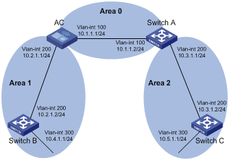
Configuration procedure
1) Configure IP addresses for interfaces (omitted)
2) Configure OSPF basic functions
# Configure AC.
<AC> system-view
[AC] ospf
[AC-ospf-1] area 0
[AC-ospf-1-area-0.0.0.0] network 10.1.1.0 0.0.0.255
[AC-ospf-1-area-0.0.0.0] quit
[AC-ospf-1] area 1
[AC-ospf-1-area-0.0.0.1] network 10.2.1.0 0.0.0.255
[AC-ospf-1-area-0.0.0.1] quit
[AC-ospf-1] quit
# Configure Switch A.
<SwitchA> system-view
[SwitchA] ospf
[SwitchA-ospf-1] area 0
[SwitchA-ospf-1-area-0.0.0.0] network 10.1.1.0 0.0.0.255
[SwitchA-ospf-1-area-0.0.0.0] quit
[SwitchA-ospf-1] area 2
[SwitchA-ospf-1-area-0.0.0.2] network 10.3.1.0 0.0.0.255
[SwitchA-ospf-1-area-0.0.0.2] quit
[SwitchA-ospf-1] quit
# Configure Switch B.
<SwitchB> system-view
[SwitchB] ospf
[SwitchB-ospf-1] area 1
[SwitchB-ospf-1-area-0.0.0.1] network 10.2.1.0 0.0.0.255
[SwitchB-ospf-1-area-0.0.0.1] network 10.4.1.0 0.0.0.255
[SwitchB-ospf-1-area-0.0.0.1] quit
[SwitchB-ospf-1] quit
# Configure Switch C.
<SwitchC> system-view
[SwitchC] ospf
[SwitchC-ospf-1] area 2
[SwitchC-ospf-1-area-0.0.0.2] network 10.3.1.0 0.0.0.255
[SwitchC-ospf-1-area-0.0.0.2] network 10.5.1.0 0.0.0.255
[SwitchC-ospf-1-area-0.0.0.2] quit
[SwitchC-ospf-1] quit
3) Verify the configuration
# Display information about neighbors on AC.
[AC] display ospf peer verbose
OSPF Process 1 with Router ID 10.2.1.1
Neighbors
Area 0.0.0.0 interface 10.1.1.1(Vlan-interface100)'s neighbors
Router ID: 10.3.1.1 Address: 10.1.1.2 GR State: Normal
State: Full Mode: Nbr is Master Priority: 1
DR: 10.1.1.1 BDR: 10.1.1.2 MTU: 0
Dead timer due in 37 sec
Neighbor is up for 06:03:59
Authentication Sequence: [ 0 ]
Neighbor state change count: 5
Neighbors
Area 0.0.0.1 interface 10.2.1.1(Vlan-interface200)'s neighbors
Router ID: 10.4.1.1 Address: 10.2.1.2 GR State: Normal
State: Full Mode: Nbr is Master Priority: 1
DR: 10.2.1.1 BDR: 10.2.1.2 MTU: 0
Dead timer due in 32 sec
Neighbor is up for 06:03:12
Authentication Sequence: [ 0 ]
Neighbor state change count: 5
# Display OSPF routing information on AC.
[AC] display ospf routing
OSPF Process 1 with Router ID 10.2.1.1
Routing Tables
Routing for Network
Destination Cost Type NextHop AdvRouter Area
10.2.1.0/24 10 Transit 10.2.1.1 10.2.1.1 0.0.0.1
10.3.1.0/24 4 Inter 10.1.1.2 10.3.1.1 0.0.0.0
10.4.1.0/24 13 Stub 10.2.1.2 10.4.1.1 0.0.0.1
10.5.1.0/24 14 Inter 10.1.1.2 10.3.1.1 0.0.0.0
10.1.1.0/24 2 Transit 10.1.1.1 10.2.1.1 0.0.0.0
Total Nets: 5
Intra Area: 3 Inter Area: 2 ASE: 0 NSSA: 0
# Display the Link State Database on AC.
[AC] display ospf lsdb
OSPF Process 1 with Router ID 10.2.1.1
Link State Database
Area: 0.0.0.0
Type LinkState ID AdvRouter Age Len Sequence Metric
Router 10.2.1.1 10.2.1.1 1069 36 80000012 0
Router 10.3.1.1 10.3.1.1 780 36 80000011 0
Network 10.1.1.1 10.2.1.1 1069 32 80000010 0
Sum-Net 10.5.1.0 10.3.1.1 780 28 80000003 12
Sum-Net 10.2.1.0 10.2.1.1 1069 28 8000000F 10
Sum-Net 10.3.1.0 10.3.1.1 780 28 80000014 2
Sum-Net 10.4.1.0 10.2.1.1 769 28 8000000F 13
Area: 0.0.0.1
Type LinkState ID AdvRouter Age Len Sequence Metric
Router 10.2.1.1 10.2.1.1 769 36 80000012 0
Router 10.4.1.1 10.4.1.1 1663 48 80000012 0
Network 10.2.1.1 10.2.1.1 769 32 80000010 0
Sum-Net 10.5.1.0 10.2.1.1 769 28 80000003 14
Sum-Net 10.3.1.0 10.2.1.1 1069 28 8000000F 4
Sum-Net 10.1.1.0 10.2.1.1 1069 28 8000000F 2
Sum-Asbr 10.3.1.1 10.2.1.1 1069 28 8000000F 2
# Display OSPF routing information on Switch C.
[SwitchC] display ospf routing
OSPF Process 1 with Router ID 10.5.1.1
Routing Tables
Routing for Network
Destination Cost Type NextHop AdvRouter Area
10.2.1.0/24 22 Inter 10.3.1.1 10.3.1.1 0.0.0.2
10.3.1.0/24 10 Transit 10.3.1.2 10.3.1.1 0.0.0.2
10.4.1.0/24 25 Inter 10.3.1.1 10.3.1.1 0.0.0.2
10.5.1.0/24 10 Stub 10.5.1.1 10.5.1.1 0.0.0.2
10.1.1.0/24 12 Inter 10.3.1.1 10.3.1.1 0.0.0.2
Total Nets: 5
Intra Area: 2 Inter Area: 3 ASE: 0 NSSA: 0
# On Switch C, ping the IP address 10.4.1.1 to check connectivity.
[SwitchC] ping 10.4.1.1
PING 10.4.1.1: 56 data bytes, press CTRL_C to break
Request time out
Reply from 10.4.1.1: bytes=56 Sequence=2 ttl=253 time=15 ms
Reply from 10.4.1.1: bytes=56 Sequence=3 ttl=253 time=1 ms
Reply from 10.4.1.1: bytes=56 Sequence=4 ttl=253 time=16 ms
Reply from 10.4.1.1: bytes=56 Sequence=5 ttl=253 time=1 ms
--- 10.4.1.1 ping statistics ---
5 packet(s) transmitted
4 packet(s) received
20.00% packet loss
round-trip min/avg/max = 1/8/16 ms
Configuring an OSPF Stub Area
Network requirements
The following figure shows an AS is split into three areas, where all switches run OSPF. AC and Switch A act as ABRs to forward routing information between areas. Switch C acts as the ASBR to redistribute routes (static routes).
It is required to configure Area 1 as a Stub area, reducing LSAs to this area without affecting route reachability.
Network diagram
Figure 3-22 Network diagram for OSPF Stub area configuration
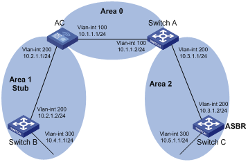
1) Configure IP addresses for interfaces (omitted).
2) Configure OSPF basic functions (refer to Configuring OSPF Basic Functions).
3) Configure Switch C to redistribute static routes.
[SwitchC] ip route-static 3.1.2.1 24 10.5.1.2
[SwitchC] ospf
[SwitchC-ospf-1] import-route static
[SwitchC-ospf-1] quit
# Display ABR/ASBR information on Switch B.
[SwitchB] display ospf abr-asbr
OSPF Process 1 with Router ID 10.4.1.1
Routing Table to ABR and ASBR
Type Destination Area Cost Nexthop RtType
Intra 10.2.1.1 0.0.0.1 3 10.2.1.1 ABR
Inter 10.3.1.1 0.0.0.1 5 10.2.1.1 ABR
Inter 10.5.1.1 0.0.0.1 7 10.2.1.1 ASBR
# Display OSPF routing table information on Switch B.
[SwitchB] display ospf routing
OSPF Process 1 with Router ID 10.4.1.1
Routing Tables
Routing for Network
Destination Cost Type NextHop AdvRouter Area
10.2.1.0/24 3 Transit 10.2.1.2 10.2.1.1 0.0.0.1
10.3.1.0/24 7 Inter 10.2.1.1 10.2.1.1 0.0.0.1
10.4.1.0/24 3 Stub 10.4.1.1 10.4.1.1 0.0.0.1
10.5.1.0/24 17 Inter 10.2.1.1 10.2.1.1 0.0.0.1
10.1.1.0/24 5 Inter 10.2.1.1 10.2.1.1 0.0.0.1
Routing for ASEs
Destination Cost Type Tag NextHop AdvRouter
3.1.2.0/24 1 Type2 1 10.2.1.1 10.5.1.1
Total Nets: 6
Intra Area: 2 Inter Area: 3 ASE: 1 NSSA: 0
![]()
In the above output, since Switch B resides in a normal OSPF area, its routing table contains an external route.
4) Configure Area 1 as a Stub area.
# Configure AC.
[AC] ospf
[AC-ospf-1] area 1
[AC-ospf-1-area-0.0.0.1] stub
[AC-ospf-1-area-0.0.0.1] quit
[AC-ospf-1] quit
# Configure Switch B.
[SwitchB] ospf
[SwitchB-ospf-1] area 1
[SwitchB-ospf-1-area-0.0.0.1] stub
[SwitchB-ospf-1-area-0.0.0.1] quit
[SwitchB-ospf-1] quit
# Display OSPF routing information on Switch B.
[SwitchB] display ospf routing
OSPF Process 1 with Router ID 10.4.1.1
Routing Tables
Routing for Network
Destination Cost Type NextHop AdvRouter Area
0.0.0.0/0 4 Inter 10.2.1.1 10.2.1.1 0.0.0.1
10.2.1.0/24 3 Transit 10.2.1.2 10.2.1.1 0.0.0.1
10.3.1.0/24 7 Inter 10.2.1.1 10.2.1.1 0.0.0.1
10.4.1.0/24 3 Stub 10.4.1.1 10.4.1.1 0.0.0.1
10.5.1.0/24 17 Inter 10.2.1.1 10.2.1.1 0.0.0.1
10.1.1.0/24 5 Inter 10.2.1.1 10.2.1.1 0.0.0.1
Total Nets: 6
Intra Area: 2 Inter Area: 4 ASE: 0 NSSA: 0
![]()
When Switch B resides in the Stub area, a default route takes the place of the external route.
# Filter Type-3 LSAs out the stub area
[AC] ospf
[AC-ospf-1] area 1
[AC-ospf-1-area-0.0.0.1] stub no-summary
[AC-ospf-1-area-0.0.0.1] quit
# Display OSPF routing information on Switch B.
[SwitchB] display ospf routing
OSPF Process 1 with Router ID 10.4.1.1
Routing Tables
Routing for Network
Destination Cost Type NextHop AdvRouter Area
0.0.0.0/0 4 Inter 10.2.1.1 10.2.1.1 0.0.0.1
10.2.1.0/24 3 Transit 10.2.1.2 10.4.1.1 0.0.0.1
10.4.1.0/24 3 Stub 10.4.1.1 10.4.1.1 0.0.0.1
Total Nets: 3
Intra Area: 2 Inter Area: 1 ASE: 0 NSSA: 0
![]()
After this configuration, routing entries on the stub router are further reduced, containing only one default external route.
Configuring an OSPF NSSA Area
Network requirements
The following figure shows an AS is split into three areas, where all switches run OSPF. AC and Switch A act as ABRs to forward routing information between areas.
It is required to configure Area 1 as an NSSA area, and configure Switch B as the ASBR to redistribute static routes into the AS.
Network diagram
Figure 3-23 Network diagram for OSPF NSSA area configuration
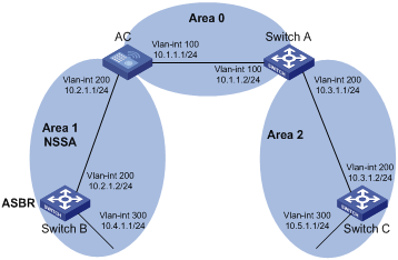
Configuration procedure
1) Configure IP addresses for interfaces.
2) Configure OSPF basic functions (refer to Configuring OSPF Basic Functions).
3) Configure Area 1 as an NSSA area.
# Configure AC.
[AC] ospf
[AC-ospf-1] area 1
[AC-ospf-1-area-0.0.0.1] nssa default-route-advertise no-summary
[AC-ospf-1-area-0.0.0.0] quit
[AC-ospf-1] quit
# Configure Switch B.
[SwitchB] ospf
[SwitchB-ospf-1] area 1
[SwitchB-ospf-1-area-0.0.0.1] nssa
[SwitchB-ospf-1-area-0.0.0.1] quit
[SwitchB-ospf-1] quit
![]()
It is recommended to configure the nssa command with the keyword default-route-advertise no-summary on AC (an ABR) to reduce the routing table size on NSSA routers. On other NSSA routers, using the nssa command is ok.
# Display OSPF routing information on Switch B.
[SwitchB] display ospf routing
OSPF Process 1 with Router ID 10.4.1.1
Routing Tables
Routing for Network
Destination Cost Type NextHop AdvRouter Area
0.0.0.0/0 65536 Inter 10.2.1.1 10.2.1.1 0.0.0.1
10.2.1.0/24 65535 Transit 10.2.1.2 10.4.1.1 0.0.0.1
10.4.1.0/24 3 Stub 10.4.1.1 10.4.1.1 0.0.0.1
Total Nets: 3
Intra Area: 2 Inter Area: 1 ASE: 0 NSSA: 0
4) Configure Switch B to redistribute static routes.
[SwitchB] ip route-static 3.1.3.1 24 11.1.1.1
[SwitchB] ospf
[SwitchB-ospf-1] import-route static
[SwitchB-ospf-1] quit
# Display OSPF routing information on Switch C.
[SwitchC-ospf-1] display ospf routing
OSPF Process 1 with Router ID 10.5.1.1
Routing Tables
Routing for Network
Destination Cost Type NextHop AdvRouter Area
10.2.1.0/24 22 Inter 10.3.1.1 10.3.1.1 0.0.0.2
10.3.1.0/24 10 Transit 10.3.1.2 10.3.1.1 0.0.0.2
10.4.1.0/24 25 Inter 10.3.1.1 10.3.1.1 0.0.0.2
10.5.1.0/24 10 Stub 10.5.1.1 10.5.1.1 0.0.0.2
10.1.1.0/24 12 Inter 10.3.1.1 10.3.1.1 0.0.0.2
Routing for ASEs
Destination Cost Type Tag NextHop AdvRouter
3.1.3.0/24 1 Type2 1 10.3.1.1 10.2.1.1
Total Nets: 6
Intra Area: 2 Inter Area: 3 ASE: 1 NSSA: 0
![]()
You can see on Switch C an external route imported from the NSSA area.
Configuring OSPF DR Election
Network requirements
l In the following figure, AC, Switches A, B and C run OSPF and reside on the same network segment.
l It is required to configure AC as the DR, and configure Switch B as the BDR.
Network diagram
Figure 3-24 Network diagram for OSPF DR election configuration
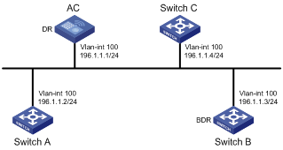
Configuration procedure
1) Configure IP addresses for interfaces (omitted)
2) Configure OSPF basic functions
# Configure AC.
<AC> system-view
[AC] router id 1.1.1.1
[AC] ospf
[AC-ospf-1] area 0
[AC-ospf-1-area-0.0.0.0] network 196.1.1.0 0.0.0.255
[AC-ospf-1-area-0.0.0.0] quit
[AC-ospf-1] quit
# Configure Switch A.
<SwitchA> system-view
[SwitchA] router id 2.2.2.2
[SwitchA] ospf
[SwitchA-ospf-1] area 0
[SwitchA-ospf-1-area-0.0.0.0] network 196.1.1.0 0.0.0.255
[SwitchA-ospf-1-area-0.0.0.0] quit
[SwitchA-ospf-1] quit
# Configure Switch B.
<SwitchB> system-view
[SwitchB] router id 3.3.3.3
[SwitchB] ospf
[SwitchB-ospf-1] area 0
[SwitchB-ospf-1-area-0.0.0.0] network 196.1.1.0 0.0.0.255
[SwitchB-ospf-1-area-0.0.0.0] quit
[SwitchB-ospf-1] quit
# Configure Switch C.
<SwitchC> system-view
[SwitchC] router id 4.4.4.4
[SwitchC] ospf
[SwitchC-ospf-1] area 0
[SwitchC-ospf-1-area-0.0.0.0] network 196.1.1.0 0.0.0.255
[SwitchC-ospf-1-area-0.0.0.0] quit
[SwitchC-ospf-1] quit
# Display OSPF neighbor information on AC.
[AC] display ospf peer verbose
OSPF Process 1 with Router ID 1.1.1.1
Neighbors
Area 0.0.0.0 interface 192.168.1.1(Vlan-interface1)'s neighbors
Router ID: 2.2.2.2 Address: 192.168.1.2 GR State: Normal
State: 2-Way Mode: None Priority: 1
DR: 192.168.1.4 BDR: 192.168.1.3 MTU: 0
Dead timer due in 38 sec
Neighbor is up for 00:01:31
Authentication Sequence: [ 0 ]
Neighbor state change count: 2
Router ID: 3.3.3.3 Address: 192.168.1.3 GR State: Normal
State: Full Mode: Nbr is Master Priority: 1
DR: 192.168.1.4 BDR: 192.168.1.3 MTU: 0
Dead timer due in 31 sec
Neighbor is up for 00:01:28
Authentication Sequence: [ 0 ]
Neighbor state change count: 2
Router ID: 4.4.4.4 Address: 192.168.1.4 GR State: Normal
State: Full Mode: Nbr is Master Priority: 1
DR: 192.168.1.4 BDR: 192.168.1.3 MTU: 0
Dead timer due in 31 sec
Neighbor is up for 00:01:28
Authentication Sequence: [ 0 ]
Neighbor state change count: 2
Switch C becomes the DR, and Switch B is the BDR.
3) Configure router priorities on interfaces
# Configure AC.
[AC] interface vlan-interface 1
[AC-Vlan-interface1] ospf dr-priority 100
[AC-Vlan-interface1] quit
# Configure Switch A.
[SwitchA] interface vlan-interface 1
[SwitchA-Vlan-interface1] ospf dr-priority 0
[SwitchA-Vlan-interface1] quit
# Configure Switch B.
[SwitchB] interface vlan-interface 1
[SwitchB-Vlan-interface1] ospf dr-priority 2
[SwitchB-Vlan-interface] quit
# Display neighbor information on Switch C.
[SwitchC] display ospf peer verbose
OSPF Process 1 with Router ID 4.4.4.4
Neighbors
Area 0.0.0.0 interface 192.168.1.4(Vlan-interface1)'s neighbors
Router ID: 1.1.1.1 Address: 192.168.1.1 GR State: Normal
State: Full Mode:Nbr is Slave Priority: 100
DR: 192.168.1.4 BDR: 192.168.1.3 MTU: 0
Dead timer due in 31 sec
Neighbor is up for 00:11:17
Authentication Sequence: [ 0 ]
Neighbor state change count: 5
Router ID: 2.2.2.2 Address: 192.168.1.2 GR State: Normal
State: Full Mode:Nbr is Slave Priority: 0
DR: 192.168.1.4 BDR: 192.168.1.3 MTU: 0
Dead timer due in 35 sec
Neighbor is up for 00:11:19
Authentication Sequence: [ 0 ]
Neighbor state change count: 5
Router ID: 3.3.3.3 Address: 192.168.1.3 GR State: Normal
State: Full Mode:Nbr is Slave Priority: 2
DR: 192.168.1.4 BDR: 192.168.1.3 MTU: 0
Dead timer due in 33 sec
Neighbor is up for 00:11:15
Authentication Sequence: [ 0 ]
Neighbor state change count: 5
The DR and BDR have no change.
![]()
In the above output, you can find the priority configuration does not take effect immediately.
4) Restart OSPF process (omitted)
# Display neighbor information on Switch C.
[SwitchC] display ospf peer verbose
OSPF Process 1 with Router ID 4.4.4.4
Neighbors
Area 0.0.0.0 interface 192.168.1.4(Vlan-interface1)'s neighbors
Router ID: 1.1.1.1 Address: 192.168.1.1 GR State: Normal
State: Full Mode: Nbr is Slave Priority: 100
DR: 192.168.1.1 BDR: 192.168.1.3 MTU: 0
Dead timer due in 39 sec
Neighbor is up for 00:01:40
Authentication Sequence: [ 0 ]
Neighbor state change count: 2
Router ID: 2.2.2.2 Address: 192.168.1.2 GR State: Normal
State: 2-Way Mode: None Priority: 0
DR: 192.168.1.1 BDR: 192.168.1.3 MTU: 0
Dead timer due in 35 sec
Neighbor is up for 00:01:44
Authentication Sequence: [ 0 ]
Neighbor state change count: 2
Router ID: 3.3.3.3 Address: 192.168.1.3 GR State: Normal
State: Full Mode: Nbr is Slave Priority: 2
DR: 192.168.1.1 BDR: 192.168.1.3 MTU: 0
Dead timer due in 39 sec
Neighbor is up for 00:01:41
Authentication Sequence: [ 0 ]
Neighbor state change count: 2
AC becomes the DR, and Switch B is the BDR.
![]()
If the neighbor state is full, it means Switch D has established the adjacency with the neighbor. If the neighbor state is 2-way, it means the two switches are neither the DR nor the BDR, and they do not exchange LSAs.
# Display OSPF interface information.
[AC] display ospf interface
OSPF Process 1 with Router ID 1.1.1.1
Interfaces
Area: 0.0.0.0
IP Address Type State Cost Pri DR BDR
192.168.1.1 Broadcast DR 1 100 192.168.1.1 192.168.1.3
[SwitchA] display ospf interface
OSPF Process 1 with Router ID 2.2.2.2
Interfaces
Area: 0.0.0.0
IP Address Type State Cost Pri DR BDR
192.168.1.2 Broadcast DROther 1 0 192.168.1.1 192.168.1.3
![]()
The interface state DROther means the interface is not the DR/BDR.
Configuring OSPF Virtual Links
Network requirements
In Figure 3-25, Area 2 has no direct connection to Area 0, and Area 1 acts as the Transit Area to connect Area 2 to Area 0 via a configured virtual link between AC and Switch.
After configuration, AC can learn routes to Area 2.
Network diagram
Figure 3-25 Network diagram for OSPF virtual link configuration
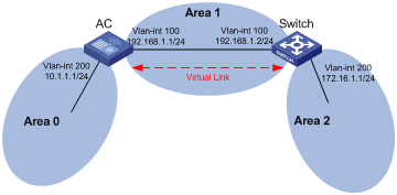
Configuration procedure
1) Configure IP addresses for interfaces (omitted)
2) Configure OSPF basic functions
# Configure AC.
<AC> system-view
[AC] ospf 1 router-id 1.1.1.1
[AC-ospf-1] area 0
[AC-ospf-1-area-0.0.0.0] network 10.0.0.0 0.255.255.255
[AC-ospf-1-area-0.0.0.0] quit
[AC-ospf-1] area 1
[AC-ospf-1-area-0.0.0.1] network 192.168.1.0 0.0.0.255
[AC-ospf-1-area-0.0.0.1] quit
# Configure Switch.
<Switch> system-view
[Switch] ospf 1 router-id 2.2.2.2
[Switch-ospf-1] area 1
[Switch-ospf-1-area-0.0.0.1] network 192.168.1.0 0.0.0.255
[Switch-ospf-1-area-0.0.0.1] quit
[Switch-ospf-1] area 2
[Switch–ospf-1-area-0.0.0.2] network 172.16.0.0 0.0.255.255
[Switch–ospf-1-area-0.0.0.2] quit
# Display OSPF routing information on AC.
[AC] display ospf routing
OSPF Process 1 with Router ID 1.1.1.1
Routing Tables
Routing for Network
Destination Cost Type NextHop AdvRouter Area
10.0.0.0/8 1 Stub 10.1.1.1 1.1.1.1 0.0.0.0
192.168.1.0/24 1562 Stub 192.168.1.1 1.1.1.1 0.0.0.1
Total Nets: 2
Intra Area: 2 Inter Area: 0 ASE: 0 NSSA: 0
![]()
Since Area 2 has no direct connection to Area 0, the OSPF routing table of AC has no route to Area 2.
3) Configure a virtual link
# Configure AC.
[AC] ospf
[AC-ospf-1] area 1
[AC-ospf-1-area-0.0.0.1] vlink-peer 2.2.2.2
[AC-ospf-1-area-0.0.0.1] quit
[AC-ospf-1] quit
# Configure Switch.
[Switch] ospf 1
[Switch-ospf-1] area 1
[Switch-ospf-1-area-0.0.0.1] vlink-peer 1.1.1.1
[Switch-ospf-1-area-0.0.0.1] quit
# Display OSPF routing information on AC.
[AC] display ospf routing
OSPF Process 1 with Router ID 1.1.1.1
Routing Tables
Routing for Network
Destination Cost Type NextHop AdvRouter Area
172.16.1.1/16 1563 Inter 192.168.1.2 2.2.2.2 0.0.0.0
10.0.0.0/8 1 Stub 10.1.1.1 1.1.1.1 0.0.0.0
192.168.1.0/24 1562 Stub 192.168.1.1 1.1.1.1 0.0.0.1
Total Nets: 3
Intra Area: 2 Inter Area: 1 ASE: 0 NSSA: 0
AC has learned the route 172.16.1.1/16 to Area 2.
OSPF Graceful Restart Configuration Example
Network requirements
l AC, Switch A and Switch B that belong to the same autonomous system and the same OSPF routing domain are GR capable.
l AC acts as the non IETF standard GR Restarter whereas Switch A and Switch B are the GR Helpers and remain OOB synchronized with AC through the GR mechanism.
Network diagram
Figure 3-26 Network diagram for OSPF-based GR configuration
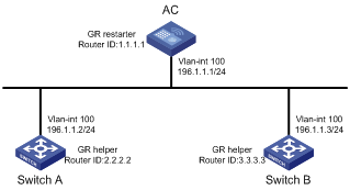
Configuration procedure
1) Configure AC
<AC> system-view
[AC] interface vlan-interface 100
[AC-Vlan-interface100] ip address 192.1.1.1 255.255.255.0
[AC-Vlan-interface100] quit
[AC] router id 1.1.1.1
[AC] ospf 100
[AC-ospf-100] enable link-local-signaling
[AC-ospf-100] enable out-of-band-resynchronization
[AC-ospf-100] graceful-restart
[AC-ospf-100] area 0
[AC-ospf-100-area-0.0.0.0] network 192.1.1.0 0.0.0.255
[AC-ospf-100-area-0.0.0.0] return
2) Configure Switch A
<SwitchA> system-view
[SwitchA] acl number 2000
[SwitchA-acl-basic-2000] rule 10 permit source 192.1.1.1 0.0.0.0
[SwitchA-acl-basic-2000] quit
[SwitchA] interface vlan-interface 100
[SwitchA-Vlan-interface100] ip address 192.1.1.2 255.255.255.0
[SwitchA-Vlan-interface100] ospf dr-priority 0
[SwitchA-Vlan-interface100] quit
[SwitchA] router id 2.2.2.2
[SwitchA] ospf 100
[SwitchA-ospf-100] enable link-local-signaling
[SwitchA-ospf-100] enable out-of-band-resynchronization
[SwitchA-ospf-100] graceful-restart help 2000
[SwitchA-ospf-100] area 0
[SwitchA-ospf-100-area-0.0.0.0] network 192.1.1.0 0.0.0.255
[SwitchA-ospf-100-area-0.0.0.0] quit
3) Configure Switch B
<SwitchB> system-view
[SwitchB] interface vlan-interface 100
[SwitchB-Vlan-interface100] ip address 192.1.1.3 255.255.255.0
[SwitchB-Vlan-interface100] ospf dr-priority 2
[SwitchB-Vlan-interface100] quit
[SwitchB] router id 3.3.3.3
[SwitchB] ospf 100
[SwitchB-ospf-100] enable link-local-signaling
[SwitchB-ospf-100] enable out-of-band-resynchronization
[SwitchB-ospf-100] area 0
[SwitchB-ospf-100-area-0.0.0.0] network 192.1.1.0 0.0.0.255
[SwitchC-ospf-100-area-0.0.0.0] quit
4) Verify the configuration
# After the configurations on AC, Switch A and Switch B are completed and the switches are running steadily, perform OSPF GR on AC.
<AC> reset ospf 100 process graceful-restart
Troubleshooting OSPF Configuration
No OSPF Neighbor Relationship Established
Symptom
No OSPF neighbor relationship can be established.
Analysis
If the physical link and lower layer protocols work well, check OSPF parameters configured on interfaces. Two neighbors must have the same parameters, such as the area ID, network segment and mask (a P2P or virtual link may have different network segments and masks), network type. If the network type is broadcast or NBMA, at least one interface must have a router priority higher than 0.
Processing steps
1) Display OSPF neighbor information using the display ospf peer command.
2) Display OSPF interface information using the display ospf interface command.
3) Ping the neighbor router’s IP address to check connectivity.
4) Check OSPF timers. The neighbor dead interval on an interface must be at least four times the hello interval.
5) On an NBMA network, using the peer ip-address command to specify the neighbor manually is required.
6) On an NBMA or a broadcast network, at least one connected interface must have a router priority higher than 0.
Incorrect Routing Information
Symptom
OSPF cannot find routes to other areas.
Analysis
The backbone area must maintain connectivity to all other areas. If a router connects to more than one area, at least one area must be connected to the backbone. The backbone cannot be configured as a Stub area.
In a Stub area, all routers cannot receive external routes, and all interfaces connected to the Stub area must belong to the Stub area.
Solution
1) Use the display ospf peer command to display neighbors.
2) Use the display ospf interface command to display OSPF interface information.
3) Use the display ospf lsdb command to display the Link State Database to check its integrity.
4) Display information about area configuration using the display current-configuration configuration ospf command. If more than two areas are configured, at least one area is connected to the backbone.
5) In a Stub area, all routers attached are configured with the stub command. In an NSSA area, all interface connected to which are configured with the nssa command.
6) If a virtual link is configured, use the display ospf vlink command to check the state of the virtual link.
