- Table of Contents
-
- H3C WX6103 Access Controller Switch Interface Board Configuration Guide-6W102
- 00-Preface
- 01-Login Configuration
- 02-VLAN Configuration
- 03-IP Addressing and IP Performance Configuration
- 04-QinQ-BPDU Tunneling Configuration
- 05-Port Correlation Configuration
- 06-Link Aggregation Configuration
- 07-MAC Address Table Management Configuration
- 08-Port Security Configuration
- 09-MSTP Configuration
- 10-IP Routing-GR Overview Configuration
- 11-IPv4 Routing Configuration
- 12-IP Source Guard Configuration
- 13-DLDP Configuration
- 14-Multicast Configuration
- 15-LLDP Configuration
- 16-sFlow Configuration
- 17-ARP Configuration
- 18-DHCP Configuration
- 19-ACL Configuration
- 20-QoS Configuration
- 21-Port Mirroring Configuration
- 22-UDP Helper Configuration
- 23-SNMP-RMON Configuration
- 24-NTP Configuration
- 25-DNS Configuration
- 26-File System Management Configuration
- 27-Information Center Configuration
- 28-System Maintaining and Debugging Configuration
- 29-NQA Configuration
- 30-SSH Configuration
- 31-SSL-HTTPS Configuration
- 32-PKI Configuration
- 33-Track Configuration
- 34-Acronyms
- 35-Index
- Related Documents
-
| Title | Size | Download |
|---|---|---|
| 01-Login Configuration | 351.91 KB |
Table of Contents
1 Logging In Through an OAP Board
Logging In to the Operating System of an OAP Board
Resetting the System of an OAP Board
Telnet Configurations for Different Authentication Modes
Telnet Configuration with Authentication Mode Being None
Telnet Configuration with Authentication Mode Being Password
Telnet Configuration with Authentication Mode Being Scheme
Telnet Connection Establishment
Telnetting to the Access controller Switch Interface Board from a Terminal
Telnetting to Another Access controller from the Current One
3 Logging In Through the Web-Based Network Management System
Establishing an HTTP Connection
5 Configuring Source IP Address for Telnet Service Packets
Configuring Source IP Address for Telnet Service Packets
Displaying the source IP address/Interface Specified for Telnet Packets
Controlling Telnet Users by Source IP Addresses
Controlling Telnet Users by Source and Destination IP Addresses
Controlling Telnet Users by Source MAC Addresses
Controlling Network Management Users by Source IP Addresses
Controlling Network Management Users by Source IP Addresses
When logging in through an OAP board, go to these sections for information you are interested in:
l Logging In to the Operating System of an OAP Board
l Resetting the System of an OAP Board
OAP Board Overview
As an open software and hardware system, Open Application Architecture (OAA) of Hangzhou H3C Technologies Co., Ltd. (referred to as H3C herein after) provides a set of complete standard software and hardware interfaces based on H3C devices. The third party vendors can develop products with special functions. These products can be compatible with H3C devices as long as they conform to the OAA interface standards. Therefore the functions of single network products can be expanded and the users can get more benefits. Open Application Platform (OAP) is developed based on OAA. It can be an independent network device, or a board used as an extended part of a device. An OAP board runs an independent operating system. You can load software such as security and voice in the operating system as needed. Meanwhile, after an OAP board is inserted into the expansion module slot of the device, it interacts with the device on data, status information and control information through its internal service interfaces
Logging In to the Operating System of an OAP Board
Logging in through the console port of the WX6103 main control board
You can log in to the operating system of the access controller interface board (an OAP board) through the console port of the main control board of the WX6103 access controller. In this example, a PC acts as a terminal.
1) Connect the serial port of the PC with the console port of the WX6103 main control board through a console cable.
2) Run the terminal emulation program such as the HyperTerminal. Select the connection mode COM and set the terminal parameters. Parameter requirements: set the bits per second to 9600, data bits to 8, parity to none, stop bits to 1, and flow control to none.
3) Enter OAP board view from user view of the WX6103 main control board.
<H3C> oap connect slot 0
After the configuration, you can log in to the operating system of the WX6103 main control board, and you can press Ctrl+K to return to the command line interface of the access controller.
Redirecting to an OAP board from the device
You can redirect to the operating system of an OAP board from the device through the following operation. In this way, the terminal display interface will be switched from the command line interface on the device to the operating interface of the operating system of the OAP board, and you can manage the system and application software on the OAP board. After the switch, you can press Ctrl+K to return to the command line interface on the device.
Follow the step to redirect from the device to the OAP board:
|
To do… |
Use the command… |
Remarks |
|
Redirect from the device to the OAP board |
oap connect slot 0 |
Required Available in user view |
Resetting the System of an OAP Board
If the operating system of an OAP board works abnormally or is under other anomalies, you can reset the OAP board with the following command.
The OAP board has its independent CPU; therefore, the access controller can still recognize and control the OAP board after you reset the OAP system.
Follow the step to reset the system of the OAP board:
|
To do… |
Use the command… |
Remarks |
|
Reset the system of the OAP board |
oap reboot slot 0 |
Required Available in user view |
![]()
Reset of the OAP board may cause data loss and service interruption. Therefore, before resetting the OAP board, you need to save the data on the operating system to avoid service interruption and hardware data loss.
When logging in through Telnet, go to these sections for information you are interested in:
l Telnet Configuration with Authentication Mode Being None
l Telnet Configuration with Authentication Mode Being Password
l Telnet Configuration with Authentication Mode Being Scheme
l Telnet Connection Establishment
Introduction
You can telnet to the switch interface board of a remote access controller to manage and maintain the board. To achieve this, you need to configure both the switch interface board of the access controller and the Telnet terminal properly.
Table 2-1 Requirements for telnetting to the switch interface board of an access controller
|
Item |
Requirement |
|
Access controller switch interface board |
Start the Telnet Server |
|
The IP address of the VLAN interface and the management interface of the access controller switch interface board are configured and the route between the access controller switch interface board and the Telnet terminal is available. (Refer to IPv4 and IP Routing in H3C WX6103 Access Controller Switch Interface Board Configuration Guide for more.) |
|
|
The authentication mode and other settings are configured. Refer to Table 2-2 and Table 2-3. |
|
|
Telnet terminal |
Telnet is running. |
|
The IP address of the management VLAN of the access controller switch interface board is available. |
![]()
l After you log in to the access controller switch interface board through Telnet, you can issue commands to the board by way of pasting session text, which cannot exceed 2000 bytes, and the pasted commands must be in the same view; otherwise, the board may not execute the commands correctly.
l If the session text exceeds 2000 bytes, you can save it in a configuration file, upload the configuration file to the access controller switch interface board and reboot the board with this configuration file. For details, refer to File System Management in H3C WX6103 Access Controller Switch Interface Board Configuration Guide.
l To log in on the access controller switch interface board using Telnet based on IPv6 is same as that based on IPv4. Refer to IPv6 Configuration Guide for details.
Common Configuration
Table 2-2 lists the common Telnet configuration.
Table 2-2 Common Telnet configuration
|
Configuration |
Description |
|
|
VTY user interface configuration |
Configure the command level available to users logging in to the VTY user interface |
Optional By default, commands of level 0 are available to users logging in to a VTY user interface. |
|
Configure the protocols the user interface supports |
Optional By default, Telnet and SSH protocol are supported. |
|
|
Set the command that is automatically executed when a user logs into the user interface |
Optional By default, no command is automatically executed when a user logs into a user interface. |
|
|
VTY terminal configuration |
Define a shortcut key for aborting tasks |
Optional The default shortcut key combination for aborting tasks is Ctrl+C. |
|
Make terminal services available |
Optional By default, terminal services are available in all user interfaces |
|
|
Set the maximum number of lines the screen can contain |
Optional By default, the screen can contain up to 24 lines. |
|
|
Set history command buffer size |
Optional By default, the history command buffer can contain up to 10 commands. |
|
|
Set the timeout time of a user interface |
Optional The default timeout time is 10 minutes. |
|
![]()
l The auto-execute command command may cause you unable to perform common configuration in the user interface, so use it with caution.
l Before executing the auto-execute command command and save your configuration, make sure you can log in to the access controller in other modes and can cancel the configuration.
Telnet Configurations for Different Authentication Modes
Table 2-3 lists Telnet configurations for different authentication modes.
Table 2-3 Telnet configurations for different authentication modes
|
Authentication mode |
Telnet configuration |
Description |
|
|
None |
Perform common configuration |
Perform common Telnet configuration |
Optional Refer to Table 2-2. |
|
Password |
Configure the password |
Configure the password for local authentication |
Required |
|
Perform common configuration |
Perform common Telnet configuration |
Optional Refer to Table 2-2. |
|
|
Scheme |
Specify to perform local authentication or RADIUS authentication |
AAA configuration specifies whether to perform local authentication or RADIUS authentication |
Optional Local authentication is performed by default. Refer to AAA-RADIUS-HWTACACS Configuration for more. |
|
Configure user name and password |
Configure user names and passwords for local/remote users |
Required l The user name and password of a local user are configured on the access controller switch interface board. l The user name and password of a remote user are configured on the RADIUS server. Refer to user manual of RADIUS server for more. |
|
|
Manage VTY users |
Set service type for VTY users |
Required |
|
|
Perform common configuration |
Perform common Telnet configuration |
Optional Refer to Table 2-2. |
|
Telnet Configuration with Authentication Mode Being None
Configuration Procedure
|
To do… |
Use the command… |
Remarks |
|
Redirect to the OAP module |
oap connect slot 0 |
— |
|
Enter system view |
system-view |
— |
|
Enable the Telnet server function |
telnet server enable |
Required |
|
Enter one or more VTY user interface views |
user-interface vty first-number [ last-number ] |
— |
|
Configure not to authenticate users logging in to VTY user interfaces |
authentication-mode none |
Required By default, VTY users are authenticated for login. |
|
Configure the command level available to users logging in to VTY user interface |
user privilege level level |
Optional By default, commands of level 0 are available to users logging in to VTY user interfaces. |
|
Configure the protocols to be supported by the VTY user interface |
protocol inbound { all | ssh | telnet } |
Optional By default, both Telnet protocol and SSH protocol are supported. |
|
Set the command that is automatically executed when a user logs into the user interface |
auto-execute command text |
Optional By default, no command is automatically executed when a user logs into a user interface. |
|
Define a shortcut key for aborting tasks |
escape-key { default | character } |
Optional The default shortcut key combination for aborting tasks is Ctrl+C. |
|
Make terminal services available |
shell |
Optional By default, terminal services are available in all user interfaces. |
|
Set the maximum number of lines the screen can contain |
screen-length screen-length |
Optional By default, the screen can contain up to 24 lines. You can use the screen-length 0 command to disable the function to display information in pages. |
|
Set the history command buffer size |
history-command max-size value |
Optional The default history command buffer size is 10. That is, a history command buffer can store up to 10 commands by default. |
|
Set the timeout time of the VTY user interface |
idle-timeout minutes [ seconds ] |
Optional The default timeout time of a user interface is 10 minutes. With the timeout time being 10 minutes, the connection to a user interface is terminated if no operation is performed in the user interface within 10 minutes. You can use the idle-timeout 0 command to disable the timeout function. |
Note that if you configure not to authenticate the users, the command level available to users logging in to an access controller switch interface board depends on both the authentication-mode none command and the user privilege level level command, as listed in Table 2-4.
Table 2-4 Determine the command level when users logging in to access controller switch interface board are not authenticated
|
Scenario |
Command level |
||
|
Authentication mode |
User type |
Command |
|
|
None (authentication-mode none) |
VTY users |
The user privilege level level command not executed |
Level 0 |
|
The user privilege level level command already executed |
Determined by the level argument |
||
Configuration Example
Network requirements
Assume that you are a level 3 Console user and want to perform the following configuration for Telnet users logging in to VTY 0:
l Users are not authenticated when logging in to VTY 0.
l Commands of level 2 are available to users logging in to VTY 0.
l Telnet protocol is supported.
l The screen can contain up to 30 lines.
l The history command buffer can contain up to 20 commands.
l The timeout time of VTY 0 is 6 minutes.
Network diagram
Figure 2-1 Network diagram for Telnet configuration
Configuration procedure
# Redirect to the access controller switch interface board.
<WX6103> oap connect slot 0
Connected to OAP!
<H3C>
# Enter system view, and enable the Telnet service.
<H3C> system-view
[H3C] telnet server enable
# Enter VTY 0 user interface view.
[H3C] user-interface vty 0
# Configure not to authenticate Telnet users logging in to VTY 0.
[H3C-ui-vty0] authentication-mode none
# Specify commands of level 2 are available to users logging in to VTY 0.
[H3C-ui-vty0] user privilege level 2
# Configure Telnet protocol is supported.
[H3C-ui-vty0] protocol inbound telnet
# Set the maximum number of lines the screen can contain to 30.
[H3C-ui-vty0] screen-length 30
# Set the maximum number of commands the history command buffer can store to 20.
[H3C-ui-vty0] history-command max-size 20
# Set the timeout time to 6 minutes.
[H3C-ui-vty0] idle-timeout 6
Telnet Configuration with Authentication Mode Being Password
Configuration Procedure
|
To do… |
Use the command… |
Remarks |
|
Enter system view |
system-view |
— |
|
Enable the Telnet server function |
telnet server enable |
Required |
|
Enter one or more VTY user interface views |
user-interface vty first-number [ last-number ] |
— |
|
Configure to authenticate users logging in to VTY user interfaces using the local password |
authentication-mode password |
Required |
|
Set the local password |
set authentication password { cipher | simple } password |
Required |
|
Configure the command level available to users logging in to the user interface |
user privilege level level |
Optional By default, commands of level 0 are available to users logging in to VTY user interface. |
|
Configure the protocol to be supported by the user interface |
protocol inbound { all | ssh | telnet } |
Optional By default, both Telnet protocol and SSH protocol are supported. |
|
Set the command that is automatically executed when a user logs into the user interface |
auto-execute command text |
Optional By default, no command is automatically executed when a user logs into a user interface. |
|
Define a shortcut key for aborting tasks |
escape-key { default | character } |
Optional The default shortcut key combination for aborting tasks is <Ctrl+C>. |
|
Make terminal services available |
shell |
Optional By default, terminal services are available in all user interfaces. |
|
Set the maximum number of lines the screen can contain |
screen-length screen-length |
Optional By default, the screen can contain up to 24 lines. You can use the screen-length 0 command to disable the function to display information in pages. |
|
Set the history command buffer size |
history-command max-size value |
Optional The default history command buffer size is 10. That is, a history command buffer can store up to 10 commands by default. |
|
Set the timeout time of the user interface |
idle-timeout minutes [ seconds ] |
Optional The default timeout time of a user interface is 10 minutes. With the timeout time being 10 minutes, the connection to a user interface is terminated if no operation is performed in the user interface within 10 minutes. You can use the idle-timeout 0 command to disable the timeout function. |
Note that if you configure to authenticate the users in the password mode, the command level available to users logging in to the access controller switch interface board depends on both the authentication-mode password command and the user privilege level level command, as listed in Table 2-5.
Table 2-5 Determine the command level when users logging in to the access controller switch interface board are authenticated in the password mode
|
Scenario |
Command level |
||
|
Authentication mode |
User type |
Command |
|
|
Password (authentication-mode password) |
VTY users |
The user privilege level level command not executed |
Level 0 |
|
The user privilege level level command already executed |
Determined by the level argument |
||
Configuration Example
Network requirements
Assume that you are a level 3 Console user and want to perform the following configuration for Telnet users logging in to VTY 0:
l Authenticate users logging in to VTY 0 using the local password.
l Set the local password to 123456 (in plain text).
l Commands of level 2 are available to users logging in to VTY 0.
l Telnet protocol is supported.
l The screen can contain up to 30 lines.
l The history command buffer can contain up to 20 commands.
l The timeout time of VTY 0 is 6 minutes.
Network diagram
Figure 2-2 Network diagram for Telnet configuration
Configuration procedure
# Enter the OAP board view from the user view of the WX6103 main control board.
<WX6103> oap connect slot 0
Connected to OAP!
<H3C>
# Enter system view of the OAP board, and enable the Telnet service.
<H3C> system-view
[H3C] telnet server enable
# Enter VTY 0 user interface view.
[H3C] user-interface vty 0
# Configure to authenticate users logging in to VTY 0 using the local password.
[H3C-ui-vty0] authentication-mode password
# Set the local password to 123456 (in plain text).
[H3C-ui-vty0] set authentication password simple 123456
# Specify commands of level 2 are available to users logging in to VTY 0.
[H3C-ui-vty0] user privilege level 2
# Configure Telnet protocol is supported.
[H3C-ui-vty0] protocol inbound telnet
# Set the maximum number of lines the screen can contain to 30.
[H3C-ui-vty0] screen-length 30
# Set the maximum number of commands the history command buffer can store to 20.
[H3C-ui-vty0] history-command max-size 20
# Set the timeout time to 6 minutes.
[H3C-ui-vty0] idle-timeout 6
Telnet Configuration with Authentication Mode Being Scheme
Configuration Procedure
|
To do… |
Use the command… |
Remarks |
|
|
Enter system view |
system-view |
— |
|
|
Enable the Telnet server function |
telnet server enable |
Required |
|
|
Configure the authentication scheme |
Enter the default ISP domain view |
domain domain-name |
Optional By default, the local AAA scheme is applied. If you specify to apply the local AAA scheme, you need to perform the configuration concerning local user as well. If you specify to apply an existing scheme by providing the radius-scheme-name argument, you need to perform the following configuration as well: l Perform AAA&RADIUS configuration on the access controller switch interface board. (Refer to AAA-RADIUS-HWTACACS Configuration for more.) l Configure the user name and password accordingly on the AAA server. (Refer to the user manual of AAA server.) |
|
Configure the AAA scheme to be applied to the domain |
authentication default { hwtacacs-scheme hwtacacs-scheme- name [ local ] | local | none | radius-scheme radius-scheme-name [ local ] } |
||
|
Quit to system view |
quit |
||
|
Create a local user and enter local user view |
local-user user-name |
No local user exists by default. |
|
|
Set the authentication password for the local user |
password { simple | cipher } password |
Required |
|
|
Specify the service type for VTY users |
service-type telnet [ level level ] |
Required |
|
|
Quit to system view |
quit |
— |
|
|
Enter one or more VTY user interface views |
user-interface vty first-number [ last-number ] |
— |
|
|
Configure to authenticate users locally or remotely |
authentication-mode scheme [ command- authorization ] |
Required The specified AAA scheme determines whether to authenticate users locally or remotely. Users are authenticated locally by default. |
|
|
Configure the command level available to users logging in to the user interface |
user privilege level level |
Optional By default, commands of level 0 are available to users logging in to the VTY user interfaces. |
|
|
Configure the supported protocol |
protocol inbound { all | ssh | telnet } |
Optional Both Telnet protocol and SSH protocol are supported by default. |
|
|
Set the command that is automatically executed when a user logs into the user interface |
auto-execute command text |
Optional By default, no command is automatically executed when a user logs into a user interface. |
|
|
Define a shortcut key for aborting tasks |
escape-key { default | character } |
Optional The default shortcut key combination for aborting tasks is Ctrl+C. |
|
|
Make terminal services available |
shell |
Optional Terminal services are available in all use interfaces by default. |
|
|
Set the maximum number of lines the screen can contain |
screen-length screen-length |
Optional By default, the screen can contain up to 24 lines. You can use the screen-length 0 command to disable the function to display information in pages. |
|
|
Set history command buffer size |
history-command max-size value |
Optional The default history command buffer size is 10. That is, a history command buffer can store up to 10 commands by default. |
|
|
Set the timeout time for the user interface |
idle-timeout minutes [ seconds ] |
Optional The default timeout time of a user interface is 10 minutes. With the timeout time being 10 minutes, the connection to a user interface is terminated if no operation is performed in the user interface within 10 minutes. You can use the idle-timeout 0 command to disable the timeout function. |
|
Note that if you configure to authenticate the users in the scheme mode, the command level available to users logging in to the access controller switch interface board depends on the authentication-mode scheme [ command-authorization ] command, the user privilege level level command, and the service-type telnet [ level level ] command, as listed in Table 2-6.
Table 2-6 Determine the command level when users logging in to the access controller switch interface board are authenticated in the scheme mode
|
Scenario |
Command level |
||
|
Authentication mode |
User type |
Command |
|
|
Scheme (authentication-mode scheme [ command-authorization ]) |
VTY users that are AAA&RADIUS authenticated or locally authenticated |
The user privilege level level command is not executed, and the service-type command does not specify the available command level. |
Level 0 |
|
The user privilege level level command is not executed, and the service-type command specifies the available command level. |
Determined by the service-type command |
||
|
The user privilege level level command is executed, and the service-type command does not specify the available command level. |
Level 0 |
||
|
The user privilege level level command is executed, and the service-type command specifies the available command level. |
Determined by the service-type command |
||
|
VTY users that are authenticated in the RSA mode of SSH |
The user privilege level level command is not executed, and the service-type command does not specify the available command level. |
Level 0 |
|
|
The user privilege level level command is not executed, and the service-type command specifies the available command level. |
|||
|
The user privilege level level command is executed, and the service-type command does not specify the available command level. |
Determined by the user privilege level level command |
||
|
The user privilege level level command is executed, and the service-type command specifies the available command level. |
|||
|
VTY users that are authenticated in the password mode of SSH |
The user privilege level level command is not executed, and the service-type command does not specify the available command level. |
Level 0 |
|
|
The user privilege level level command is not executed, and the service-type command specifies the available command level. |
Determined by the service-type command |
||
|
The user privilege level level command is executed, and the service-type command does not specify the available command level. |
Level 0 |
||
|
The user privilege level level command is executed, and the service-type command specifies the available command level. |
Determined by the service-type command |
||
![]()
Refer to SSH in H3C WX6103 Access Controller Switch Interface Board Configuration Guide for information about SSH.
Configuration Example
Network requirements
Assume that you are a level 3 Console user and want to perform the following configuration for Telnet users logging in to VTY 0:
l Configure the name of the local user as guest.
l Set the authentication password of the local user to 123456 (in plain text).
l Set the service type of VTY users to Telnet.
l Configure to authenticate users logging in to VTY 0 in scheme mode.
l The commands of level 2 are available to users logging in to VTY 0.
l Telnet protocol is supported in VTY 0.
l The screen can contain up to 30 lines.
l The history command buffer can store up to 20 commands.
l The timeout time of VTY 0 is 6 minutes.
Network diagram
Figure 2-3 Network diagram for Telnet configuration
Configuration procedure
# Enter the OAP board view from the user view of the WX6103 main control board.
<WX6103> oap connect slot 0
Connected to OAP!
<H3C>
# Enter system view, and enable the Telnet service.
<H3C> system-view
[H3C] telnet server enable
# Create a local user named guest and enter local user view.
[H3C] local-user guest
# Set the authentication password of the local user to 123456 (in plain text).
[H3C-luser-guest] password simple 123456
# Set the service type to Telnet, Specify commands of level 2 are available to users logging in to VTY 0.
[H3C-luser-guest] service-type telnet level 2
# Enter VTY 0 user interface view.
[H3C] user-interface vty 0
# Configure to authenticate users logging in to VTY 0 in the scheme mode.
[H3C-ui-vty0] authentication-mode scheme
# Configure Telnet protocol is supported.
[H3C-ui-vty0] protocol inbound telnet
# Set the maximum number of lines the screen can contain to 30.
[H3C-ui-vty0] screen-length 30
# Set the maximum number of commands the history command buffer can store to 20.
[H3C-ui-vty0] history-command max-size 20
# Set the timeout time to 6 minutes.
[H3C-ui-vty0] idle-timeout 6
Telnet Connection Establishment
Telnetting to the Access controller Switch Interface Board from a Terminal
Step 1: Log in to the access controller through any Ethernet interface (Layer 3).
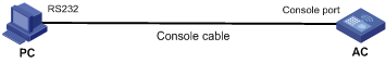
l Connect to the console port. Connect the serial port of your PC (or terminal) to the console port of the access controller (AC), as shown in Figure 2-4:
Figure 2-4 Diagram for setting the connection to the console port
l Execute the following commands in the terminal window to assign an IP address to the interface of the access controller switch interface board.
# Configure the IP address of the Ethernet interface on the access controller switch interface board as 202.38.160.92, with the subnet mask 255.255.255.0.
<H3C> system-view
[H3C]interface Vlan-interface 1
[H3C-Vlan-interface1]ip add 202.38.160.92 255.255.255.0
![]()
By default, all interfaces of the switch interface board of an access controller belong to VLAN 1. Therefore, you only need to configure the IP address of the VLAN interface without configuring the VLAN it belongs to.
Step 2: Before Telnet users can log in to the access controller switch interface board, corresponding configurations should have been performed on the access controller according to different authentication modes for them. Refer to section Telnet Configuration with Authentication Mode Being None, section Telnet Configuration with Authentication Mode Being Password, and section Telnet Configuration with Authentication Mode Being Scheme for more. By default, Telnet users need to pass the password authentication to login.
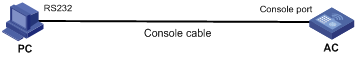
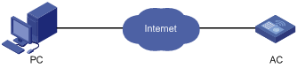
Step 3: Connect your PC to any interface of the access controller switch interface board, as shown in Figure 2-5. Make sure the route between the PC and the interface of the board is available if the PC and the board are not in the same LAN.
Figure 2-5 Network diagram for Telnet connection establishment

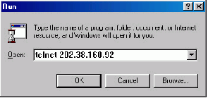
Step 4: Launch Telnet on your PC, input the IP address of the management Ethernet interface of the access controller, as shown in the following figure.
Step 5: Enter the password when the Telnet window displays Login authentication and prompts for login password. The CLI prompt (such as <H3C>) appears if the password provided is correct. If all VTY user interfaces of the access controller are in use, you will fail to establish the connection and receive the message that says “The number of users currently using the system configuration has reached the maximum. Please wait until one of the users releases the system configuration.”. An access controller can accommodate up to five Telnet connections at same time.
Step 6: After successfully Telnetting to an access controller, you can configure the access controller or display the information about the access controller by executing corresponding commands. You can also type ? at any time for help. Refer to Basic Configuration Commands.chapter in System Maintaining and Debugging in H3C WX6103 Access Controller Switch Interface Board Command Reference.
![]()
l A Telnet connection will be terminated if you remove or modify the IP address of the VLAN interface in the Telnet session.
l By default, commands of level 0 are available to Telnet users authenticated by password. Refer to Basic Configuration chapter in System Maintaining and Debugging in H3C WX6103 Access Controller Switch Interface Board Configuration Guide for information about command level.
Telnetting to Another Access controller from the Current One
You can Telnet to another access controller switch interface board from the current access controller switch interface board. In this case, the current switch interface board operates as the client, and the other operates as the server. If the interconnected Ethernet ports of the two switch interface boards are in the same LAN segment, make sure the IP addresses of the two Ethernet ports are of the same network segment, or the route between the two ports is available.
As shown in Figure 2-7, after Telnetting to an access controller (labeled as Telnet client), you can Telnet to another access controller (labeled as Telnet server) by executing the telnet command and then to configure the latter.
Figure 2-7 Network diagram for telnetting to another access controller switch interface board from the current one

Step 1: Configure the user name and password for Telnet on the access controller switch interface board operating as the Telnet server. Refer to section Telnet Configuration with Authentication Mode Being None, section Telnet Configuration with Authentication Mode Being Password, and section Telnet Configuration with Authentication Mode Being Scheme for more. By default, Telnet users need to pass the password authentication to login.
Step 2: Telnet to the access controller operating as the Telnet client.
Step 3: Execute this command on the access controller operating as the Telnet client: telnet xxxx, where xxxx is the IP address or the host name of the access controller switch interface board operating as the Telnet server. You can use the ip host to assign a host name to a access controller.
Step 4: Enter the password. If the password is correct, the CLI prompt (such as <H3C>) appears. If all VTY user interfaces of the access controller are in use, you will fail to establish the connection and receive the message that says “The number of users currently using the system configuration has reached the maximum. Please wait until one of the users releases the system configuration”.
Step 5: After successfully Telnetting to the access controller, you can configure the access controller or display the information about it by executing corresponding commands. You can also type ? at any time for help. Refer to Basic Configuration Commands.chapter in System Maintaining and Debugging in H3C WX6103 Access Controller Switch Interface Board Command Reference.
When logging in through the Web-based network management system, go to these sections for information you are interested in:
l Establishing an HTTP Connection
Introduction
Each WX6103 access controller switch interface board has a built-in Web server. It enables you to log in to the WX6103 from a Web browser to manage and maintain the device intuitively. To do this, you need to perform the actions described in Table 3-1.
Table 3-1 Configuration for logging in to the WX6103 through Web
|
On device |
Do these… |
|
Access controller switch interface board |
Assign an IP address to the VLAN interface (the management interface) of the access controller switch interface board. Ensure that the board and the management terminal have at least one reachable route to each other. |
|
Create a user account for logging to the access controller switch interface board. |
|
|
PC operating as the network management terminal |
Make sure that Internet Explorer (IE) is available. |
|
Obtain the IP address of the VLAN interface of the access controller interface board, the user name and password of the user account created on the board. |
Establishing an HTTP Connection
1) Before logging in to the access controller switch interface board (AC in Figure 3-1) from a Web-based network management system, assign an IP address to the VLAN interface on the access controller switch interface board, and create a user account for the login user.
# Assign an IP address to the VLAN interface on the access controller switch interface board.
<H3C> system-view
[H3C] interface Vlan-interface 1
[H3C-Vlan-interface1] ip address 192.168.0.100 24
[H3C-Vlan-interface1] quit
# Create a Web user account, setting both the user name and the password to admin and the user level to 3 (manage level).
[H3C] local-user admin
[H3C-luser-admin] service-type telnet
[H3C-luser-admin] level 3
[H3C-luser-admin] password simple admin
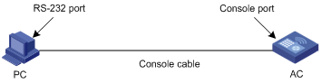
2) Establish an HTTP connection between your PC and the switch interface board, as shown in the following figure.
Figure 3-1 Establish an HTTP connection between your PC and the switch interface board
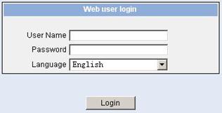
3) Log in to the switch interface board through IE. Launch IE on the Web-based network management terminal (your PC) and enter http://192.168.0.100 in the address bar (Make sure the route between the Web-based network management terminal and the switch interface board is available). When the login authentication interface (as shown in Figure 3-2) appears, enter the user name and the password admin and click Login to enter the main page of the Web-based network management system.
Figure 3-2 The login page of the Web-based network management system
When logging in from an NMS, go to these sections for information you are interested in:
Introduction
You can also log in to an access controller from an NMS (network management station), and then configure and manage the access controller through the agent module on the access controller. The environment of NMS is as follows:
l The network management station.
l The agent here refers to the server-side software running on network devices (access controllers).
l SNMP (Simple Network Management Protocol) is applied between the NMS and the agent.
To log in to an access controller from an NMS, you need to perform related configuration on both the NMS and the access controller.
Table 4-1 Requirements for logging in to an access controller through an NMS
|
Item |
Requirement |
|
Access controller |
The IP address of the management VLAN of the access controller is configured. The route between the NMS and the access controller is available. (Refer to the module IPv4 Routing in H3C WX6103 Access Controller Switch Interface Board Configuration Guide for more.) |
|
The basic SNMP functions are configured. (Refer to SNMP-RMON in H3C WX6103 Access Controller Switch Interface Board Configuration Guide for more.) |
|
|
NMS |
The NMS is properly configured. (Refer to the user manual of your NMS for more.) |
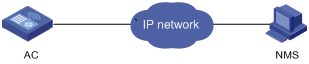
Connection Establishment
Figure 4-1 Network diagram for logging in from an NMS
Go to these sections for information you are interested in:
l Overview
l Configuring Source IP Address for Telnet Service Packets
l Displaying the source IP address/Interface Specified for Telnet Packets
Overview
You can configure source IP address or source interface for Telnet client. This provides a way to manage services and enhances security.
The source IP address specified for Telnet service packets is the IP address of a Loopback interface or VLAN interface. After you specify the IP address of a virtual Loopback interface or an unused VLAN interface as the source IP address of Telnet service packets, the IP address is used as the source IP address no matter which interface of the access controller is used to transmit packets between the Telnet client and the Telnet server. This conceals the IP address of the actual interface used. As a result, external attacks are guarded and the security is improved. On the other hand, you can configure the Telnet server to accept only Telnet service packets with specific source IP addresses to make sure specific users can log in to the access controller.
Configuring Source IP Address for Telnet Service Packets
This feature can be configured in either user view or system view. The configuration performed in user view takes effect for only the current session, while the configuration performed in system view takes effect for all the following sessions.
Configuration in user view
Table 5-1 Configure a source IP address for service packets in user view
|
To do… |
Use the command… |
Remarks |
|
Specify the source IP address or source interface for the access controller for it to log in to another device as a Telnet client |
telnet remote-system [ port-number ] [ source { ip ip-address | interface interface-type interface-number } ] |
Optional Not specified by default |
Configuration in system view
Table 5-2 Configure a source IP address for service packets in system view
|
To do… |
Use the command… |
Remarks |
|
Enter system view |
system-view |
— |
|
Specify the source IP address or source interface for the access controller for it to log in to another device as a Telnet client |
telnet client source { ip ip-address | interface interface-type interface-number } |
Optional Not specified by default |
![]()
To perform the configurations listed in Table 5-1 and Table 5-2, make sure that:
l The IP address specified is that of the local device.
l The interface specified must have existed.
l If a source IP address (or source interface) is specified, you need to make sure that the route between the IP addresses (or interface) of both sides is reachable.
Displaying the source IP address/Interface Specified for Telnet Packets
Follow these steps to display the source IP address/interface specified for Telnet packets:
|
To do… |
Use the command… |
|
Display the source IP address/interface specified for Telnet packets |
display telnet client configuration |
To control login users, go to these sections for information you are interested in:
l Controlling Network Management Users by Source IP Addresses
Introduction
An access controller provides ways to control different types of login users, as listed in Table 6-1.
Table 6-1 Ways to control different types of login users
|
Login mode |
Control method |
Implementation |
Related section |
|
Telnet |
By source IP addresses |
Through basic ACLs |
|
|
By source and destination IP addresses |
Through advanced ACLs |
Controlling Telnet Users by Source and Destination IP Addresses |
|
|
By source MAC addresses |
Through Layer 2 ACLs |
||
|
SNMP |
By source IP addresses |
Through basic ACLs |
Controlling Telnet Users
Prerequisites
The controlling policy against Telnet users is determined, including the source and destination IP addresses to be controlled and the controlling actions (permitting or denying).
Controlling Telnet Users by Source IP Addresses
Controlling Telnet users by source IP addresses is achieved by applying basic ACLs, which are numbered from 2000 to 2999. Refer to ACL in H3C WX6103 Access Controller Switch Interface Board Configuration Guide for information about defining an ACL.
|
Use the command… |
Remarks |
|
|
Enter system view |
system-view |
— |
|
Create a basic ACL or enter basic ACL view |
acl [ ipv6 ] number acl-number [ match-order { config | auto } ] |
As for the acl number command, the config keyword is specified by default. |
|
Define rules for the ACL |
rule [ rule-id ] { permit | deny } [ source { sour-addr sour-wildcard | any } | time-range time-name | fragment | logging ]* |
Required |
|
Quit to system view |
quit |
— |
|
Enter user interface view |
user-interface [ type ] first-number [ last-number ] |
— |
|
Apply the ACL to control Telnet users by source IP addresses |
acl [ ipv6 ] acl-number { inbound | outbound } |
Required The inbound keyword filters the users trying to Telnet to the current access controller. The outbound keyword filters the users trying to Telnet to other access controllers from the current access controller. |
Controlling Telnet Users by Source and Destination IP Addresses
Controlling Telnet users by source and destination IP addresses is achieved by applying advanced ACLs, which are numbered from 3000 to 3999. Refer to ACL in H3C WX6103 Access Controller Switch Interface Board Configuration Guide for information about defining an ACL.
|
To do… |
Use the command… |
Remarks |
|
Enter system view |
system-view |
— |
|
Create an advanced ACL or enter advanced ACL view |
acl [ ipv6 ] number acl-number [ name acl-name ] [ match-order { config | auto } ] |
As for the acl number command, the config keyword is specified by default. |
|
Define rules for the ACL |
rule [ rule-id ] { permit | deny } rule-string |
Required You can define rules as needed to filter by specific source and destination IP addresses. |
|
Quit to system view |
quit |
— |
|
Enter user interface view |
user-interface [ type ] first-number [ last-number ] |
— |
|
Apply the ACL to control Telnet users by specified source and destination IP addresses |
acl [ ipv6 ] acl-number { inbound | outbound } |
Required The inbound keyword filters the users trying to Telnet to the current access controller. The outbound keyword filters the users trying to Telnet to other access controllers from the current access controller. |
Controlling Telnet Users by Source MAC Addresses
Controlling Telnet users by source MAC addresses is achieved by applying Layer 2 ACLs, which are numbered from 4000 to 4999. Refer to ACL in H3C WX6103 Access Controller Switch Interface Board Configuration Guide for information about defining an ACL.
|
To do… |
Use the command… |
Remarks |
|
Enter system view |
system-view |
— |
|
Create a basic ACL or enter basic ACL view |
acl number acl-number [ name acl-name ] [ match-order { config | auto } ] |
As for the acl number command, the config keyword is specified by default. |
|
Define rules for the ACL |
rule [ rule-id ] { permit | deny } rule-string |
Required You can define rules as needed to filter by specific source MAC addresses. |
|
Quit to system view |
quit |
— |
|
Enter user interface view |
user-interface [ type ] first-number [ last-number ] |
— |
|
Apply the ACL to control Telnet users by source MAC addresses |
acl acl-number inbound |
Required The inbound keyword filters the users trying to Telnet to the current access controller. |
Configuration Example
Network requirements
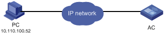
Only the Telnet users sourced from the IP address of 10.110.100.52 are permitted to log in to the access controller.
Network diagram
Figure 6-1 Network diagram for controlling Telnet users using ACLs
Configuration procedure
# Define a basic ACL.
<H3C> system-view
[H3C] acl number 2000 match-order config
[H3C-acl-basic-2000] rule 1 permit source 10.110.100.52 0
[H3C-acl-basic-2000] quit
# Apply the ACL to only permit Telnet users sourced from the IP addresses of 10.110.100.52 to access the access controller..
[H3C] user-interface vty 0 4
[H3C-ui-vty0-4] acl 2000 inbound
Controlling Network Management Users by Source IP Addresses
You can manage an access controller through network management software. Network management users can access controllers through SNMP.
You need to perform the following two operations to control network management users by source IP addresses.
l Defining an ACL
l Applying the ACL to control users accessing the access controller through SNMP
Prerequisites
The controlling policy against network management users is determined, including the source IP addresses to be controlled and the controlling actions (permitting or denying).
Controlling Network Management Users by Source IP Addresses
Controlling network management users by source IP addresses is achieved by applying basic ACLs, which are numbered from 2000 to 2999. Refer to ACL in H3C WX6103 Access Controller Switch Interface Board Configuration Guide for information about defining an ACL.
|
To do… |
Use the command… |
Remarks |
|
Enter system view |
system-view |
— |
|
Create a basic ACL or enter basic ACL view |
acl number acl-number [ name name-number ] [ match-order { config | auto } ] |
As for the acl number command, the config keyword is specified by default. |
|
Define rules for the ACL |
rule [ rule-id ] { permit | deny } [ source { sour-addr sour-wildcard | any } | time-range time-name | fragment | logging ]* |
Required |
|
Quit to system view |
quit |
— |
|
Apply the ACL while configuring the SNMP community name |
snmp-agent community { read | write } community-name [ mib-view view-name | acl acl-number ]* |
Required |
|
Apply the ACL while configuring the SNMP group name |
snmp-agent group { v1 | v2c } group-name [ read-view read-view ] [ write-view write-view ] [ notify-view notify-view ] [ acl acl-number ] snmp-agent group v3 group-name [ authentication | privacy ] [ read-view read-view ] [ write-view write-view ] [ notify-view notify-view ] [ acl acl-number ] |
Required |
|
Apply the ACL while configuring the SNMP user name |
snmp-agent usm-user { v1 | v2c } user-name group-name [ acl acl-number ] snmp-agent usm-user v3 user-name group-name [cipher ] [ authentication-mode { md5 | sha } auth-password [ privacy-mode { des56 | aes128 } priv-password ] ] [ acl acl-number ] |
Required |
![]()
l You can specify different ACLs while configuring the SNMP community name, the SNMP group name and the SNMP user name.
l Refer to SNMP-RMON in H3C WX6103 Access Controller Switch Interface Board Command Reference for SNMP-related commands.
As SNMP community name is a feature of SNMPv1 and SNMPv2c, the specified ACLs in the command that configures SNMP community names (the snmp-agent community command) take effect in the network management systems that adopt SNMPv1 or SNMPv2c.
Similarly, as SNMP group name and SNMP user name are features of SNMPv2c and the higher SNMP versions, the specified ACLs in the commands that configure SNMP group names (the snmp-agent group command and the snmp-agent group v3 command) and SNMP user names (the snmp-agent usm-user command and the snmp-agent usm-user v3 command) take effect in the network management systems that adopt SNMPv2c or higher SNMP versions. If you configure both the SNMP group name and the SNMP user name and specify ACLs in the two operations, the access controller will filter network management users by both SNMP group name and SNMP user name.
Configuration Example
Network requirements
Only SNMP users sourced from the IP addresses of 10.110.100.52 is permitted to access the access controller.
Network diagram
Figure 6-2 Network diagram for controlling SNMP users using ACLs
Configuration procedure
# Define a basic ACL.
<H3C> system-view
[H3C] acl number 2000 match-order config
[H3C-acl-basic-2000] rule 1 permit source 10.110.100.52 0
[H3C-acl-basic-2000] quit
# Apply the ACL to only permit SNMP users sourced from the IP addresses of 10.110.100.52 to access the access controller.
[H3C] snmp-agent community read h3c acl 2000
[H3C] snmp-agent group v2c h3cgroup acl 2000
[H3C] snmp-agent usm-user v2c h3cuser h3cgroup acl 2000
