- Table of Contents
-
- H3C S3600 Operation Manual-Release 1602(V1.02)
- 00-1Cover
- 00-2Product Overview
- 01-CLI Operation
- 02-Login Operation
- 03-Configuration File Management Operation
- 04-VLAN Operation
- 05-IP Address and Performance Operation
- 06-Voice VLAN Operation
- 07-GVRP Operation
- 08-Port Basic Configuration Operation
- 09-Link Aggregation Operation
- 10-Port Isolation Operation
- 11-Port Security-Port Binding Operation
- 12-DLDP Operation
- 13-MAC Address Table Management Operation
- 14-Auto Detect Operation
- 15-MSTP Operation
- 16-Routing Protocol Operation
- 17-Multicast Operation
- 18-802.1x and System Guard Operation
- 19-AAA Operation
- 20-Web Authentication Operation
- 21-MAC Address Authentication Operation
- 22-VRRP Operation
- 23-ARP Operation
- 24-DHCP Operation
- 25-ACL Operation
- 26-QoS-QoS Profile Operation
- 27-Web Cache Redirection Operation
- 28-Mirroring Operation
- 29-IRF Fabric Operation
- 30-Cluster Operation
- 31-PoE-PoE Profile Operation
- 32-UDP Helper Operation
- 33-SNMP-RMON Operation
- 34-NTP Operation
- 35-SSH Operation
- 36-File System Management Operation
- 37-FTP-SFTP-TFTP Operation
- 38-Information Center Operation
- 39-System Maintenance and Debugging Operation
- 40-VLAN-VPN Operation
- 41-HWPing Operation
- 42-IPv6 Management Operation
- 43-DNS Operation
- 44-Smart Link-Monitor Link Operation
- 45-Access Management Operation
- 46-Appendix
- Related Documents
-
| Title | Size | Download |
|---|---|---|
| 45-Access Management Operation | 87.06 KB |
Table of Contents
1 Access Management Configuration
Access Management Configuration Examples
Access Management Configuration Example
Combining Access Management with Port Isolation
1 Access Management Configuration
When configuring access management, go to these sections for information you are interested in:
l Configuring Access Management
l Access Management Configuration Examples
Access Management Overview
Normally, client PCs in a network are connected to switches operating on the network access layer (also referred to as access switches) through Layer 2 switches; and the access switches provide external network accesses for the client PCs through their upstream links. In the network shown in Figure 1-1, Switch A is an access switch; Switch B is a Layer 2 switch.
Figure 1-1 Typical Ethernet access networking scenario
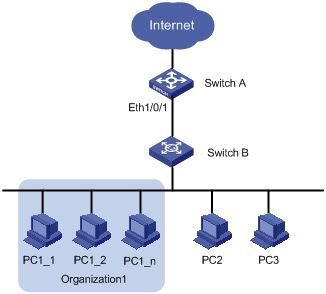
The access management function aims to manage user access rights on access switches. It enables you to manage the external network access rights of the hosts connected to ports of an access switch.
To implement the access management function, you need to configure an IP address pool on a port of an access switch, that is, bind a specified range of IP addresses to the port.
l A port with an access management IP address pool configured only allows the hosts with their IP addresses in the access management IP address pool to access external networks.
l A port without an access management IP address pool configured allows the hosts to access external networks only if their IP addresses are not in the access management IP address pools of other ports of the switch.
Note that the IP addresses in the access management IP address pool configured on a port must be in the same network segment as the IP address of the VLAN (where the port belongs to) interface.
Configuring Access Management
Follow these steps to configure access management:
|
To do… |
Use the command… |
Remarks |
|
Enter system view |
system-view |
— |
|
Enable access management function |
am enable |
Required By default, the system disables the access management function. |
|
Enable access management trap |
am trap enable |
Required By default, access management trap is disabled |
|
Enter Ethernet port view |
interface interface-type interface-number |
— |
|
Configure the access management IP address pool of the port |
am ip-pool address-list |
Required By default, no access management IP address pool is configured. |
|
Display current configuration of access management |
display am [ interface-list ] |
Execute this command in any view. |
![]()
l Before configuring the access management IP address pool of a port, you need to configure the interface IP address of the VLAN to which the port belongs, and the IP addresses in the access management IP address pool of a port must be in the same network segment as the interface IP address of the VLAN which the port belongs to.
l If an access management address pool configured contains IP addresses that belong to the static ARP entries of other ports, the system prompts you to delete the corresponding static ARP entries to ensure the access management IP address pool can take effect.
l To allow only the hosts with their IP addresses in the access management address pool of a port to access external networks, do not configure static ARP entries for IP addresses not in the IP address pool.
Access Management Configuration Examples
Access Management Configuration Example
Network requirements
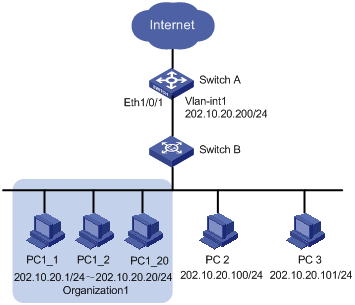
Client PCs are connected to the external network through Switch A (an Ethernet switch). The IP addresses of the PCs of Organization 1 are in the range 202.10.20.1/24 to 202.10.20.20/24. The IP address of PC 2 is 202.10.20.100/24, and that of PC 3 is 202.10.20.101/24.
l Allow the PCs of Organization 1 to access the external network through Ethernet 1/0/1 on Switch A. The port belongs to VLAN 1, and the IP address of VLAN-interface 1 is 202.10.20.200/24.
l Disable the PCs that are not of Organization 1 (PC 2 and PC 3) from accessing the external network through Ethernet 1/0/1 of Switch A.
Network diagram
Figure 1-2 Network diagram for access management configuration
Configuration procedure
Perform the following configuration on Switch A.
# Enable access management.
<Sysname> system-view
[Sysname] am enable
# Set the IP address of VLAN-interface 1 to 202.10.20.200/24.
[Sysname] interface Vlan-interface 1
[Sysname-Vlan-interface1] ip address 202.10.20.200 24
[Sysname-Vlan-interface1] quit
# Configure the access management IP address pool on Ethernet 1/0/1.
[Sysname] interface Ethernet 1/0/1
[Sysname-Ethernet1/0/1] am ip-pool 202.10.20.1 20
Combining Access Management with Port Isolation
Network requirements
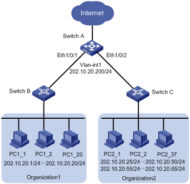
Client PCs are connected to the external network through Switch A (an Ethernet switch). The IP addresses of the PCs of Organization 1 are in the range 202.10.20.1/24 to 202.10.20.20/24, and those of the PCs in Organization 2 are in the range 202.10.20.25/24 to 202.10.20.50/24 and the range 202.10.20.55 to 202.10.20.65/24.
l Allow the PCs of Organization 1 to access the external network through Ethernet 1/0/1 of Switch A.
l Allow the PCs of Organization 2 to access the external network through Ethernet 1/0/2 of Switch A.
l Ethernet 1/0/1 and Ethernet 1/0/2 belong to VLAN 1. The IP address of VLAN-interface 1 is 202.10.20.200/24.
l PCs of Organization 1 are isolated from those of Organization 2 on Layer 2.
Network diagram
Figure 1-3 Network diagram for combining access management and port isolation
Configuration procedure
Perform the following configuration on Switch A.
For information about port isolation and the corresponding configuration, refer to the Port Isolation Operation.
# Enable access management.
<Sysname> system-view
[Sysname] am enable
# Set the IP address of VLAN-interface 1 to 202.10.20.200/24.
[Sysname] interface Vlan-interface 1
[Sysname-Vlan-interface1] ip address 202.10.20.200 24
[Sysname-Vlan-interface1] quit
# Configure the access management IP address pool on Ethernet 1/0/1.
[Sysname] interface Ethernet 1/0/1
[Sysname-Ethernet1/0/1] am ip-pool 202.10.20.1 20
# Add Ethernet 1/0/1 to the port isolation group.
[Sysname-Ethernet1/0/1] port isolate
[Sysname-Ethernet1/0/1] quit
# Configure the access management IP address pool on Ethernet 1/0/2.
[Sysname] interface Ethernet 1/0/2
[Sysname-Ethernet1/0/2] am ip-pool 202.10.20.25 26 202.10.20.55 11
# Add Ethernet 1/0/2 to the port isolation group.
[Sysname-Ethernet1/0/2] port isolate
[Sysname-Ethernet1/0/2] quit
