- Table of Contents
-
- H3C S3600 Operation Manual-Release 1602(V1.02)
- 00-1Cover
- 00-2Product Overview
- 01-CLI Operation
- 02-Login Operation
- 03-Configuration File Management Operation
- 04-VLAN Operation
- 05-IP Address and Performance Operation
- 06-Voice VLAN Operation
- 07-GVRP Operation
- 08-Port Basic Configuration Operation
- 09-Link Aggregation Operation
- 10-Port Isolation Operation
- 11-Port Security-Port Binding Operation
- 12-DLDP Operation
- 13-MAC Address Table Management Operation
- 14-Auto Detect Operation
- 15-MSTP Operation
- 16-Routing Protocol Operation
- 17-Multicast Operation
- 18-802.1x and System Guard Operation
- 19-AAA Operation
- 20-Web Authentication Operation
- 21-MAC Address Authentication Operation
- 22-VRRP Operation
- 23-ARP Operation
- 24-DHCP Operation
- 25-ACL Operation
- 26-QoS-QoS Profile Operation
- 27-Web Cache Redirection Operation
- 28-Mirroring Operation
- 29-IRF Fabric Operation
- 30-Cluster Operation
- 31-PoE-PoE Profile Operation
- 32-UDP Helper Operation
- 33-SNMP-RMON Operation
- 34-NTP Operation
- 35-SSH Operation
- 36-File System Management Operation
- 37-FTP-SFTP-TFTP Operation
- 38-Information Center Operation
- 39-System Maintenance and Debugging Operation
- 40-VLAN-VPN Operation
- 41-HWPing Operation
- 42-IPv6 Management Operation
- 43-DNS Operation
- 44-Smart Link-Monitor Link Operation
- 45-Access Management Operation
- 46-Appendix
- Related Documents
-
| Title | Size | Download |
|---|---|---|
| 08-Port Basic Configuration Operation | 129.2 KB |
Table of Contents
Configuring Port Auto-Negotiation Speed
Limiting Traffic on individual Ports
Enabling Flow Control on a Port
Duplicating the Configuration of a Port to Other Ports
Configuring Loopback Detection for an Ethernet Port
Enabling the System to Test Connected Cable
Configuring the Interval to Perform Statistical Analysis on Port Traffic
Enabling Giant-Frame Statistics Function
Disabling Up/Down Log Output on a Port
Configuring Storm Control on a Port
Setting the Port State Change Delay
Displaying and Maintaining Basic Port Configuration
Ethernet Port Configuration Example
Troubleshooting Ethernet Port Configuration
When performing basic port configuration, go to these sections for information you are interested in:
l Ethernet Port Configuration Example
l Troubleshooting Ethernet Port Configuration
![]()
l The auto-negotiation speed configuration was added to this manual. For details, refer to Configuring Port Auto-Negotiation Speed.
l The configuration of disabling port Up/Down log output was added to this manual. For details, refer to Disabling Up/Down Log Output on a Port.
l The storm control function was added to this manual. For details, refer to Configuring Storm Control on a Port.
l The displaying and maintaining of the statistics on dropped packets was added to this manual. For details, refer to Displaying and Maintaining Basic Port Configuration.
l The port state change delay configuration was added to this manual. For details, refer to Setting the Port State Change Delay.
Ethernet Port Configuration
Initially Configuring a Port
Follow these steps to initially configure a port:
|
To do... |
Use the command... |
Remarks |
|
Enter system view |
system-view |
— |
|
Enter Ethernet port view |
interface interface-type interface-number |
— |
|
Enable the Ethernet port |
undo shutdown |
Optional By default, the port is enabled. Use the shutdown command to disable the port. |
|
Set the description string for the Ethernet port |
description text |
Optional By default, the description string of an Ethernet port is null. |
|
Set the duplex mode of the Ethernet port |
duplex { auto | full | half } |
Optional By default, the duplex mode of the port is auto (auto-negotiation). |
|
Set the speed of the Ethernet port |
speed { 10 | 100 | 1000 | auto } |
Optional l By default, the speed of an Ethernet port is determined through auto-negotiation (the auto keyword). l Use the 1000 keyword for Gigabit Ethernet ports only. |
|
Set the medium dependent interface (MDI) mode of the Ethernet port |
mdi { across | auto | normal } |
Optional Be default, the MDI mode of an Ethernet port is auto. |
|
Set the maximum frame size allowed on the Ethernet port to 9,216 bytes |
jumboframe enable |
Optional By default, the maximum frame size allowed on an Ethernet is 9,216 bytes. To set the maximum frame size allowed on an Ethernet port to 1,536 bytes, use the undo jumboframe enable command. |
Configuring Port Auto-Negotiation Speed
You can configure an auto-negotiation speed for a port by using the speed auto command.
Take a 10/100/1000 Mbps port as an example.
l If you expect that 10 Mbps is the only available auto-negotiation speed of the port, you just need to configure speed auto 10.
l If you expect that 10 Mbps and 100 Mbps are the available auto-negotiation speeds of the port, you just need to configure speed auto 10 100.
l If you expect that 10 Mbps and 1000 Mbps are the available auto-negotiation speeds of the port, you just need to configure speed auto 10 1000.
Follow these steps to configure auto-negotiation speeds for a port:
|
To do... |
Use the command... |
Remarks |
|
system-view |
— |
|
|
Enter Ethernet interface view |
interface interface-type interface-number |
— |
|
Configure the available auto-negotiation speed(s) for the port |
speed auto [ 10 | 100 | 1000 ]* |
Optional l By default, the port speed is determined through auto-negotiation. l Use the 1000 keyword for Gigabit Ethernet ports only. |
![]()
l Only ports on the front panel of the device support the auto-negotiation speed configuration feature. And ports on the extended interface card do not support this feature currently.
l After you configure auto-negotiation speed(s) for a port, if you execute the undo speed command or the speed auto command, the auto-negotiation speed setting of the port restores to the default setting.
l The effect of executing speed auto 10 100 1000 equals to that of executing speed auto, that is, the port is configured to support all the auto-negotiation speeds: 10 Mbps, 100 Mbps, and 1000 Mbps.
Limiting Traffic on individual Ports
By performing the following configurations, you can limit the incoming broadcast/multicast/unknown unicast traffic on individual ports. When a type of incoming traffic exceeds the threshold you set, the system drops the packets exceeding the traffic limit to reduce the traffic ratio of this type to the reasonable range, so as to keep normal network service.
Follow these steps to limit traffic on port:
|
To do... |
Use the command... |
Remarks |
|
Enter system view |
system-view |
— |
|
Limit broadcast traffic received on each port |
broadcast-suppression { ratio | pps max-pps } |
Optional By default, the switch does not suppress broadcast traffic. |
|
Enter Ethernet port view |
interface interface-type interface-number |
— |
|
Limit broadcast traffic received on the current port |
broadcast-suppression { ratio | pps max-pps } |
Optional By default, the switch does not suppress broadcast traffic. |
|
Limit multicast traffic received on the current port |
multicast-suppression { ratio | pps max-pps } |
Optional By default, the switch does not suppress multicast traffic. |
|
Limit unknown unicast traffic received on the current port |
unicast-suppression { ratio | pps max-pps } |
Optional By default, the switch does not suppress unknown unicast traffic. |
Enabling Flow Control on a Port
Flow control is enabled on both the local and peer switches. If congestion occurs on the local switch:
l The local switch sends a message to notify the peer switch of stopping sending packets to itself or reducing the sending rate temporarily.
l The peer switch will stop sending packets to the local switch or reduce the sending rate temporarily when it receives the message; and vice versa. By this way, packet loss is avoided and the network service operates normally.
Follow these steps to enable flow control on a port:
|
To do... |
Use the command... |
Remarks |
|
Enter system view |
system-view |
— |
|
Enter Ethernet port view |
interface interface-type interface-number |
— |
|
Enable flow control on the Ethernet port |
flow-control |
By default, flow control is not enabled on the port. |
Duplicating the Configuration of a Port to Other Ports
To make other ports have the same configuration as that of a specific port, you can duplicate the configuration of a port to specific ports.
Specifically, the following types of port configuration can be duplicated from one port to other ports: VLAN configuration, protocol-based VLAN configuration, LACP configuration, QoS configuration, GARP configuration, STP configuration and initial port configuration. Refer to the command manual for the configurations that can be duplicated.
Follow these steps to duplicate the configuration of a port to specific ports:
|
To do... |
Use the command... |
Remarks |
|
Enter system view |
system-view |
— |
|
Duplicate the configuration of a port to specific ports |
copy configuration source { interface-type interface-number | aggregation-group source-agg-id } destination { interface-list [ aggregation-group destination-agg-id ] | aggregation-group destination-agg-id } |
Required |
![]()
l If you specify a source aggregation group ID, the system will use the port with the smallest port number in the aggregation group as the source.
l If you specify a destination aggregation group ID, the configuration of the source port will be copied to all ports in the aggregation group and all ports in the group will have the same configuration as that of the source port.
Configuring Loopback Detection for an Ethernet Port
Loopback detection is used to monitor if loopback occurs on a switch port.
After you enable loopback detection on Ethernet ports, the switch can monitor if external loopback occurs on them. If there is a loopback port found, the switch will put it under control.
l If loopback is found on an access port, the system disables the port, sends a Trap message to the client and removes the corresponding MAC forwarding entry.
l If loopback is found on a trunk or hybrid port, the system sends a Trap message to the client. When the loopback port control function is enabled on these ports, the system disables the port, sends a Trap message to the client and removes the corresponding MAC forwarding entry.
Follow these steps to configure loopback detection for an Ethernet port:
|
To do... |
Use the command... |
Remarks |
|
Enter system view |
system-view |
— |
|
Enable loopback detection globally |
loopback-detection enable |
Required By default, loopback detection is disabled globally. |
|
Set the interval for performing port loopback detection |
loopback-detection interval-time time |
Optional The default is 30 seconds. |
|
Enter Ethernet port view |
interface interface-type interface-number |
— |
|
Enable loopback detection on a specified port |
loopback-detection enable |
Required By default, port loopback detection is disabled. |
|
Enable loopback port control on the trunk or hybrid port |
loopback-detection control enable |
Optional By default, loopback port control is not enabled. |
|
Configure the system to run loopback detection on all VLANs of the current trunk or hybrid port |
loopback-detection per-vlan enable |
Optional By default, the system runs loopback detection only on the default VLAN of the current trunk or hybrid port. |
![]()
l To enable loopback detection on a specific port, you must use the loopback-detection enable command in both system view and the specific port view.
l After you use the undo loopback-detection enable command in system view, loopback detection will be disabled on all ports.
Enabling Loopback Test
You can configure the Ethernet port to run loopback test to check if it operates normally. The port running loopback test cannot forward data packets normally. The loopback test terminates automatically after a specific period.
Follow these steps to enable loopback test:
|
To do... |
Use the command... |
Remarks |
|
Enter system view |
system-view |
— |
|
Enter Ethernet port view |
interface interface-type interface-number |
— |
|
Enable loopback test |
loopback { external | internal } |
Required |
![]()
l external: Performs external loop test. In the external loop test, self-loop headers must be used on the port of the switch ( for 100M port, the self-loop headers are made from four cores of the 8-core cables, for 1000M port, the self-loop header are made from eight cores of the 8-core cables, then the packets forwarded by the port will be received by itself.). The external loop test can locate the hardware failures on the port.
l internal: Performs internal loop test. In the internal loop test, self loop is established in the switching chip to locate the chip failure which is related to the port.
Note that:
l After you use the shutdown command on a port, the port cannot run loopback test.
l You cannot use the speed, duplex, mdi and shutdown commands on the ports running loopback test.
l Some ports do not support loopback test, and corresponding prompts will be given when you perform loopback test on them.
Enabling the System to Test Connected Cable
You can enable the system to test the cable connected to a specific port. The test result will be returned in five seconds. The system can test these attributes of the cable: Receive and transmit directions (RX and TX), short circuit/open circuit or not, the length of the faulty cable.
Follow these steps to enable the system to test connected cables:
|
To do... |
Use the command... |
Remarks |
|
Enter system view |
system-view |
— |
|
Enter Ethernet port view |
interface interface-type interface-number |
— |
|
Enable the system to test connected cables |
virtual-cable-test |
Required |
Configuring the Interval to Perform Statistical Analysis on Port Traffic
By performing the following configuration, you can set the interval to perform statistical analysis on the traffic of a port.
When you use the display interface interface-type interface-number command to display the information of a port, the system performs statistical analysis on the traffic flow passing through the port during the specified interval and displays the average rates in the interval. For example, if you set this interval to 100 seconds, the displayed information is as follows:
Last 100 seconds input: 0 packets/sec 0 bytes/sec
Last 100 seconds output: 0 packets/sec 0 bytes/sec
Follow these steps to set the interval to perform statistical analysis on port traffic:
|
To do... |
Use the command... |
Remarks |
|
Enter system view |
system-view |
— |
|
Enter Ethernet port view |
interface interface-type interface-number |
— |
|
Set the interval to perform statistical analysis on port traffic |
flow-interval interval |
Optional By default, this interval is 300 seconds. |
Enabling Giant-Frame Statistics Function
The giant-frame statistics function is used to ensure normal data transmission and to facilitate statistics and analysis of unusual traffic on the network.
Follow these steps to enable the giant-frame statistics function:
|
To do... |
Use the command... |
Remarks |
|
Enter system view |
system-view |
— |
|
Enable the giant-frame statistics function |
giant-frame statistics enable |
Required By default, the giant-frame statistics function is not enabled. |
Disabling Up/Down Log Output on a Port
An Ethernet port has three physical link statuses: Up, Down, and Administratively Down. For status transition conditions, refer to the description of the display brief interface command in Basic Port Configuration Command.
When the physical link status of an Ethernet port changes between Up and Down or Up and Administratively Down, the switch will generate Up/Down log and send the log information to the terminal automatically by default. If the status of Ethernet ports in a network changes frequently, large amount of log information may be sent to the terminal, which consumes more network resources. Additionally, too frequent log information is not convenient for you to view.
You can limit the amount of the log information sent to the terminal by disabling the Up/Down log output function on some Ethernet ports selectively. For information about log output settings, refer to the Information Center module.
Disable Up/Down log output on a port
Follow these steps to disable UP/Down log output on a port:
|
To do... |
Use the command... |
Remarks |
|
Enter system view |
system-view |
— |
|
Enter Ethernet port view |
interface interface-type interface-number |
— |
|
Disable a port from generating UP/Down log |
undo enable log updown |
Required By default, UP/Down log output is enabled. |
Configuration examples
# In the default conditions, where UP/DOWN log output is enabled, execute the shutdown command or the undo shutdown command on Ethernet 1/0/1. The Up/Down log information for Ethernet 1/0/1 is generated and displayed on the terminal.
<Sysname> system-view
System View: return to User View with Ctrl+Z.
[Sysname] interface Ethernet 1/0/1
[Sysname-Ethernet1/0/1] shutdown
%Apr 5 07:25:37:634 2000 Sysname L2INF/5/PORT LINK STATUS CHANGE:- 1 -
Ethernet1/0/1 is DOWN
[Sysname-Ethernet1/0/1] undo shutdown
%Apr 5 07:25:56:244 2000 Sysname L2INF/5/PORT LINK STATUS CHANGE:- 1 -
Ethernet1/0/1 is UP
# Disable Ethernet 1/0/1 from generating Up/Down log information and execute the shutdown command or the undo shutdown command on Ethernet 1/0/1. No Up/Down log information is generated or output for Ethernet 1/0/1.
[Sysname-Ethernet1/0/1] undo enable log updown
[Sysname-Ethernet1/0/1] shutdown
[Sysname-Ethernet1/0/1] undo shutdown
Configuring Storm Control on a Port
The storm control function is used to control traffic received on an Ethernet port.
l With traffic upper and lower thresholds specified on a port, the system periodically collects statistics about the broadcast/multicast/unicast/ traffic on the port. Once it finds that a type of traffic exceeds the specified upper threshold, it blocks this type of traffic on the port or directly shuts down the port, and outputs trap/log information according to your configuration.
l When a type of traffic on the port falls back to the specified lower threshold, the system cancels the blocking of this type of traffic on the port or brings up the port to restore traffic forwarding for the port, and outputs log/trap information according to your configuration.
Follow these steps to configure storm control on a port:
|
To do... |
Use the command... |
Remarks |
|
Enter system view |
system-view |
— |
|
Enter Ethernet port view |
interface interface-type interface-number |
— |
|
Set the upper and lower thresholds of broadcast/multicast/unicast traffic received on the port |
storm-constrain { broadcast | multicast | unicast } max-packets min-packets pps |
Required |
|
Set the action to be taken when a type of traffic received on the port exceeds the upper threshold. |
storm-constrain control { block | shutdown } |
Optional By default, no action is taken when a type of traffic reaches the upper threshold. |
|
Enable log/trap information to be output when a type of traffic received on the port exceeds the upper threshold or falls below the lower threshold |
storm-constrain enable { log | trap } |
Optional Enabled by default. |
|
Return to system view |
quit |
— |
|
Set the interval at which the port collects traffic statistics |
storm-constrain interval interval-value |
Optional It is 10 seconds by default. |
![]()
l If the fabric function is enabled on a port of a device, you cannot configure the storm control function on all ports of the device.
l If the broadcast-suppression command, multicast-suppression command or unicast suppression command is configured on a port, you cannot configure the storm control function on the port, and vice versa.
l You are not recommended to set the upper and lower traffic thresholds to the same value.
l If you specify the block keyword when executing the storm-constrain control command, only the packets beyond the upper thresholds are blocked when the overall traffic exceeds the upper threshold. In this case, the blocked packets are still taken into account when generating traffic statistics. If you specify the shutdown keyword when executing the command, the port will be shut down when the traffic passing through the port exceeds the upper threshold. You bring up the port again by executing the undo shutdown or the undo storm-constrain { all | broadcast | multicast | unicast } command.
Setting the Port State Change Delay
During a short period after you connect your switch to another device, the connecting port may go up and down frequently due to hardware compatibility, resulting in service interruption.
To avoid situations like this, you may introduce a port state change delay.
![]()
The port state change delay takes effect when the port goes down but not when the port goes up.
Follow these steps to set the port state change delay:
|
To do … |
Use the command … |
Remarks |
|
Enter system view |
system-view |
— |
|
Enter Ethernet interface view |
interface interface-type interface-number |
— |
|
Set the port state change delay |
link-delay delay-time |
Required Defaults to 0, which indicates that no delay is introduced. |
![]()
The delay configured in this way does not take effect for ports in DLDP down state. For information about the DLDP down state, refer to DLDP.
Displaying and Maintaining Basic Port Configuration
|
To do... |
Use the command... |
Remarks |
|
Display port configuration information |
display interface [ interface-type | interface-type interface-number ] |
Available in any view |
|
Display the enable/disable status of port loopback detection |
display loopback-detection |
|
|
Display brief information about port configuration |
display brief interface [ interface-type [ interface-number ] ] [ | { begin | include | exclude } regular-expression ] |
|
|
Display port information about a specified unit |
display unit unit-id interface |
|
|
Display the storm control configurations. |
display storm-constrain [ interface interface-type interface-number ] [ | { begin | exclude | include } regular-expression ] |
|
|
Display the statistics on the packets dropped on a port or all ports |
display packet-drop { interface [ interface-type interface-number ] | summary } |
|
|
Display the information about the port with the link-delay command configured |
display link-delay |
|
|
Clear the statistics on packets dropped on a port or all ports |
reset packet-drop interface [ interface-type interface-number ] |
Available in user view |
|
Clear port statistics |
reset counters interface [ interface-type | interface-type interface-number ] |
Available in user view After 802.1x is enabled on a port, clearing the statistics on the port will not work. |
Ethernet Port Configuration Example
Network requirements
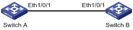
l Switch A and Switch B are connected to each other through two trunk port (Ethernet 1/0/1).
l Configure the default VLAN ID of both Ethernet 1/0/1 to 100.
l Allow the packets of VLAN 2, VLAN 6 through VLAN 50 and VLAN 100 to pass both Ethernet 1/0/1.
Network diagram
Figure 1-1 Network diagram for Ethernet port configuration
Configuration procedure
![]()
l Only the configuration for Switch A is listed below. The configuration for Switch B is similar to that of Switch A.
l This example supposes that VLAN 2, VLAN 6 through VLAN 50 and VLAN 100 have been created.
# Enter Ethernet 1/0/1 port view.
<Sysname> system-view
[Sysname] interface ethernet 1/0/1
# Set Ethernet 1/0/1 as a trunk port.
[Sysname-Ethernet1/0/1] port link-type trunk
# Allow packets of VLAN 2, VLAN 6 through VLAN 50 and VLAN 100 to pass Ethernet 1/0/1.
[Sysname-Ethernet1/0/1] port trunk permit vlan 2 6 to 50 100
# Configure the default VLAN ID of Ethernet 1/0/1 to 100.
[Sysname-Ethernet1/0/1] port trunk pvid vlan 100
Troubleshooting Ethernet Port Configuration
Symptom: Fail to configure the default VLAN ID of an Ethernet port.
Solution: Take the following steps:
l Use the display interface or display port command to check if the port is a trunk port or a hybrid port.
l If the port is not a trunk or hybrid port, configure it to be a trunk or hybrid port.
l Configure the default VLAN ID of the port.
