- Table of Contents
-
- H3C S3600 Operation Manual-Release 1602(V1.02)
- 00-1Cover
- 00-2Product Overview
- 01-CLI Operation
- 02-Login Operation
- 03-Configuration File Management Operation
- 04-VLAN Operation
- 05-IP Address and Performance Operation
- 06-Voice VLAN Operation
- 07-GVRP Operation
- 08-Port Basic Configuration Operation
- 09-Link Aggregation Operation
- 10-Port Isolation Operation
- 11-Port Security-Port Binding Operation
- 12-DLDP Operation
- 13-MAC Address Table Management Operation
- 14-Auto Detect Operation
- 15-MSTP Operation
- 16-Routing Protocol Operation
- 17-Multicast Operation
- 18-802.1x and System Guard Operation
- 19-AAA Operation
- 20-Web Authentication Operation
- 21-MAC Address Authentication Operation
- 22-VRRP Operation
- 23-ARP Operation
- 24-DHCP Operation
- 25-ACL Operation
- 26-QoS-QoS Profile Operation
- 27-Web Cache Redirection Operation
- 28-Mirroring Operation
- 29-IRF Fabric Operation
- 30-Cluster Operation
- 31-PoE-PoE Profile Operation
- 32-UDP Helper Operation
- 33-SNMP-RMON Operation
- 34-NTP Operation
- 35-SSH Operation
- 36-File System Management Operation
- 37-FTP-SFTP-TFTP Operation
- 38-Information Center Operation
- 39-System Maintenance and Debugging Operation
- 40-VLAN-VPN Operation
- 41-HWPing Operation
- 42-IPv6 Management Operation
- 43-DNS Operation
- 44-Smart Link-Monitor Link Operation
- 45-Access Management Operation
- 46-Appendix
- Related Documents
-
| Title | Size | Download |
|---|---|---|
| 12-DLDP Operation | 64.87 KB |
When configuring DLDP, go to these sections for information you are interested in:
l Overview
Overview
Introduction
A special kind of links, namely, unidirectional links, may occur in a network. When a unidirectional link appears, the local device can receive packets from the peer device through the link layer, but the peer device cannot receive packets from the local device. Unidirectional link can cause problems such as loops in a Spanning Tree Protocol (STP) enabled network.
Unidirectional links can be caused by
l Fiber cross-connection, as shown in Figure 1-1
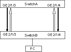
l Fibers that are not connected or disconnected, as shown in Figure 1-2, the hollow lines in which refer to fibers that are not connected or disconnected.
The Device Link Detection Protocol (DLDP) can detect the link status of an optical fiber cable or copper twisted pair (such as super category 5 twisted pair). If DLDP finds a unidirectional link, it disables the related port automatically or prompts you to disable it manually according to the configurations, to avoid network problems.
Figure 1-1 Fiber cross-connection
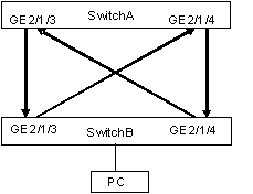
Figure 1-2 Fiber broken or not connected
DLDP provides the following features:
l As a link layer protocol, it works together with the physical layer protocols to monitor the link status of a device.
l The auto-negotiation mechanism at the physical layer detects physical signals and faults. DLDP identifies peer devices and unidirectional links, and disables unreachable ports.
l Even if both ends of links can work normally at the physical layer, DLDP can detect whether these links are connected correctly and whether packets can be exchanged normally at both ends. However, the auto-negotiation mechanism cannot implement this detection.
![]()
l In order for DLDP to detect fiber disconnection in one direction, you need to configure the port to work in mandatory full duplex mode at a mandatory rate.
l When the port determines the duplex mode and speed through auto-negotiation, even if DLDP is enabled, it does not take effect when the fiber in one direction is disconnected. In this case, the port is considered down.
DLDP Fundamentals
DLDP status
A link can be in one of these DLDP states: initial, inactive, active, advertisement, probe, disable, and delaydown.
|
Status |
Description |
|
Initial |
Initial status before DLDP is enabled. |
|
Inactive |
DLDP is enabled but the corresponding link is down |
|
Active |
This state indicates that: l DLDP is enabled and the link is up. l The neighbor entries are cleared. |
|
Advertisement |
All neighbors communicate normally in both directions, or DLDP remains in active state for more than five seconds and enters this status. It is a stable state where no unidirectional link is found |
|
Probe |
DLDP sends packets to check whether the link is a unidirectional link. It enables the probe sending timer and an echo waiting timer for each target neighbor. |
|
Disable |
DLDP detects a unidirectional link, or finds (in enhanced mode) that a neighbor disappears. In this case, DLDP does not receive or send DLDP packets. |
|
Delaydown |
When a device in the active, advertisement, or probe DLDP state receives a port down message, it does not removes the corresponding neighbor immediately, neither does it changes to the inactive state. Instead, it changes to the delaydown state first. When a device changes to the delaydown state, the related DLDP neighbor information remains, and the Delaydown timer is triggered. |
DLDP timers
|
Timer |
Description |
|
Advertisement sending timer |
Interval between sending advertisement packets, which can be configured on a command line interface. By default, the timer length is 5 seconds. |
|
Probe sending timer |
The interval is 0.5 seconds. In the probe state, DLDP sends two probe packets in a second. |
|
Echo waiting timer |
It is enabled when DLDP enters the probe state. The echo waiting timer length is 10 seconds. If no echo packet is received from the neighbor when the Echo waiting timer expires, the state of the local end is set to unidirectional link (one-way audio) and the state machine turns into the disable state. DLDP outputs log and tracking information, sends flush packets. Depending on the user-defined DLDP down mode, DLDP disables the local port automatically or prompts you to disable the port manually. At the same time, DLDP deletes the neighbor entry. |
|
Entry aging timer |
When a new neighbor joins, a neighbor entry is created and the corresponding entry aging timer is enabled When an advertisement packet is received from a neighbor, the neighbor entry is updated and the corresponding entry aging timer is updated In the normal mode, if no packet is received from the neighbor when the entry aging timer expires, DLDP sends an advertisement packet with an RSY tag, and deletes the neighbor entry. In the enhanced mode, if no packet is received from the neighbor when the entry aging timer expires, DLDP enables the enhanced timer The entry aging timer length is three times the advertisement timer length. |
|
Enhanced timer |
In the enhanced mode, if no packet is received from the neighbor when the entry aging timer expires, DLDP enables the enhanced timer for the neighbor. The enhanced timer length is 10 seconds The enhanced timer then sends one probe packet every second and eight packets successively to the neighbor. If no echo packet is received from the neighbor when the enhanced timer expires, the state of the local end is set to unidirectional communication state and the state machine turns into the disable state. DLDP outputs log and tracking information and sends flush packets. Depending on the user-defined DLDP down mode, DLDP disables the local port automatically or prompts you to disable the port manually. Meanwhile, DLDP deletes the neighbor entry. |
|
Delaydown timer |
When a device in the active, advertisement, or probe DLDP state receives a port down message, it does not removes the corresponding neighbor immediately, neither does it changes to the inactive state. Instead, it changes to the delaydown state first. When a device changes to the delaydown state, the related DLDP neighbor information remains, and the Delaydown timer is triggered. The Delaydown timer is configurable and ranges from 1 to 5 seconds. A device in the delaydown state only responds to port up messages. A device in the delaydown state resumes its original DLDP state if it receives a port up message before the delaydown timer expires. Otherwise, it removes the DLDP neighbor information and changes to the inactive state. |
DLDP operating mode
DLDP can operate in two modes: normal mode and enhanced mode.
Table 1-3 DLDP operating mode and neighbor entry aging
|
DLDP operating mode |
DLDP detects whether neighbors exist or not when neighbor tables are aging |
The entry aging timer is enabled or not during neighbor entry aging |
The enhanced timer is enabled or not when the entry aging timer expires |
|
Normal mode |
No |
Yes (The neighbor entry ages out after the entry aging timer expires) |
No |
|
Enhanced mode |
Yes |
Yes (The enhanced timer is enabled after the entry aging timer expires) |
Yes (When the enhanced timer expires, the state of the local end is set to unidirectional link, and the neighbor entry is aged out.) |
DLDP implementation
1) If the DLDP-enabled link is up, DLDP sends DLDP packets to the peer device, and analyzes and processes the DLDP packets received from the peer device. DLDP in different states sends different types of packets.
Table 1-4 Types of packets sent by DLDP
|
DLDP state |
Packet type |
|
Active |
Advertisement packets, including those with or without an RSY tag |
|
Advertisement |
Advertisement packets |
|
Probe |
Probe packets |
2) DLDP analyzes and processes received packets from the peer device as follows:
l In authentication mode, DLDP authenticates the packets, and discards those failing to pass the authentication.
l DLDP processes the received DLDP packets.
Table 1-5 Process received DLDP packets
|
Packet type |
Processing procedure |
||||
|
Advertisement packet |
Extracts neighbor information |
If this neighbor entry does not exist on the local device, DLDP creates the neighbor entry, enables the entry aging timer, and switches to the probe state. |
|||
|
If the neighbor entry already exists on the local device, DLDP updates the entry aging timer. |
|||||
|
Flush packet |
Deletes the neighbor entry from the local device |
||||
|
Probe packet |
Sends echo packets containing both neighbor and its own information to the peer |
Creates the neighbor entry if this neighbor entry does not exist on the local device. |
|||
|
If the neighbor entry already exists on the local device, updates the entry aging timer. |
|||||
|
Echo packet |
Checks whether the local device is in the probe state |
No |
Discards this echo packet |
||
|
Yes |
Checks whether neighbor information in the packet is the same as that on the local device |
No |
Discards this echo packet |
||
|
Yes |
Sets the neighbor flag bit to bidirectional link |
||||
|
If all neighbors are in the bidirectional link state, DLDP switches from the probe state to the advertisement state, and sets the echo waiting timer to 0. |
|||||
3) If no echo packet is received from the neighbor, DLDP performs the following processing:
Table 1-6 Processing procedure when no echo packet is received from the neighbor
|
No echo packet received from the neighbor |
Processing procedure |
|
In normal mode, no echo packet is received when the echo waiting timer expires. |
DLDP switches to the disable state, outputs log and tracking information, and sends flush packets. Depending on the user-defined DLDP down mode, DLDP disables the local port automatically or prompts you to disable the port manually. DLDP sends an RSY message and deletes the neighbor entry. |
|
In enhanced mode, no echo packet is received when the enhanced timer expires |
DLDP neighbor state
A DLDP neighbor can be in one of these two states: two way and unknown. You can check the state of a DLDP neighbor by using the display dldp command.
Table 1-7 Description on the two DLDP neighbor states
|
DLDP neighbor state |
Description |
|
Two way |
The link to the neighbor operates properly. |
|
Unknown |
The device is detecting the neighbor and the neighbor state is unknown. |
DLDP Configuration
Performing Basic DLDP Configuration
Follow these steps to perform basic DLDP configuration:
|
Use the command … |
Remarks |
|||
|
Enter system view |
system-view |
— |
||
|
Enable DLDP |
Enable DLDP globally |
dldp enable |
Required. By default, DLDP is disabled. |
|
|
Enable DLDP on a port |
Enter Ethernet port view |
interface interface-type interface-number |
||
|
Enable DLDP |
dldp enable |
|||
|
Set the authentication mode and password |
dldp authentication-mode { none | simple simple-password | md5 md5-password } |
Optional. By default, the authentication mode is none. |
||
|
Set the interval of sending DLDP packets |
dldp interval timer-value |
Optional. By default, the interval is 5 seconds. |
||
|
Set the delaydown timer |
dldp delaydown-timer delaydown-time |
Optional By default, the delaydown timer expires after 1 second it is triggered. |
||
|
Set the DLDP handling mode when an unidirectional link is detected |
dldp unidirectional-shutdown { auto | manual } |
Optional. By default, the handling mode is auto. |
||
|
Set the DLDP operating mode |
dldp work-mode { enhance | normal } |
Optional. By default, DLDP works in normal mode. |
||
Note the following when performing basic DLDP configuration.
l DLDP works only when the link is up.
l To ensure unidirectional links can be detected, make sure DLDP is enabled on both sides; and the interval for sending advertisement packets, authentication mode, and password are the same on both sides.
l The interval for sending advertisement packets ranges from 1 to 100 seconds and defaults to 5 seconds. You can adjust this setting as needed to enable DLDP to respond in time to link failures. If the interval is too long, STP loops may occur before unidirectional links are terminated; if the interval is too short, network traffic may increase in vain and available bandwidth decreases. Normally, the interval is shorter than one-third of the STP convergence time, which is generally 30 seconds.
l DLDP does not process any LACP event, and treats each link in the aggregation group as independent.
l When connecting two DLDP-enabled devices, make sure the software running on them is of the same version. Otherwise, DLDP may operate improperly.
l When you use the dldp enable/dldp disable command in system view to enable/disable DLDP on all optical ports of the switch, the configuration takes effect on the existing optical ports, instead of those added subsequently.
l Make sure the authentication mode and password configured on both sides are the same for DLDP to operate properly.
l When DLDP works in enhanced mode, the system can identify two types of unidirectional links: one is caused by fiber cross-connection and the other is caused by one fiber being not connected or being disconnected.
l When DLDP works in normal mode, the system can identify unidirectional links caused by fiber cross-connection.
l When the device is busy with services and the CPU utilization is high, DLDP may issue mistaken reports. You are recommended to configure the operating mode of DLDP as manual after unidirectional links are detected, so as to reduce the influence of mistaken reports.
Resetting DLDP State
You can reset the DLDP state for the ports shut down by DLDP due to unidirectional links to enable DLDP detection again.
![]()
This function is only applicable to ports that are in DLDP down state.
Follow these steps to reset DLDP state:
|
To do … |
Use the command … |
Remarks |
|
Reset DLDP state for all the ports shut down by DLDP |
system-view |
Select either of the two. |
|
dldp reset |
||
|
Reset the DLDP state for a port shut down by DLDP |
interface interface-type interface-number |
|
|
dldp reset |
Displaying and Maintaining DLDP
|
To do … |
Use the command … |
Remarks |
|
Display the DLDP configuration of a unit or a port |
display dldp { unit-id | interface-type interface-number } |
Available in any view. |
DLDP Configuration Example
Network requirements
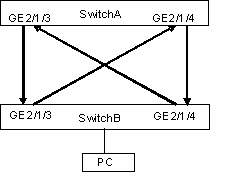
As shown in Figure 1-3,
l Switch A and Switch B are connected through two pairs of fibers. Both of them support DLDP. All the ports involved operate in mandatory full duplex mode, with their rates all being 1,000 Mbps.
l Suppose the fibers between Switch A and Switch B are cross-connected. DLDP disconnects the unidirectional links after detecting them.
l After the fibers are connected correctly, the ports shut down by DLDP are restored.
Network diagram
Figure 1-3 Network diagram for DLDP configuration
Configuration procedure
1) Configure Switch A
# Configure the ports to work in mandatory full duplex mode at a rate of 1,000 Mbps.
<SwitchA> system-view
[SwitchA] interface gigabitethernet 2/1/3
[SwitchA-GigabitEthernet2/1/3] duplex full
[SwitchA-GigabitEthernet2/1/3] speed 1000
[SwitchA-GigabitEthernet2/1/3] quit
[SwitchA] interface gigabitethernet 2/1/4
[SwitchA-GigabitEthernet2/1/4] duplex full
[SwitchA-GigabitEthernet2/1/4] speed 1000
[SwitchA-GigabitEthernet2/1/4] quit
# Enable DLDP globally.
[SwitchA] dldp enable
# Set the interval for sending DLDP packets to 15 seconds.
[SwitchA] dldp interval 15
# Configure DLDP to work in enhanced mode.
[SwitchA] dldp work-mode enhance
# Set the DLDP handling mode for unidirectional links to auto.
[SwitchA] dldp unidirectional-shutdown auto
# Display the DLDP state.
[SysnameA] display dldp 1
![]()
When two switches are connected through fibers in a crossed way, two or three ports may be in the disable state, and the rest in the inactive state.
When a fiber is connected to a device correctly on one end with the other end connected to no device:
l If the device operates in the normal DLDP mode, the end that receives optical signals is in the advertisement state; the other end is in the inactive state.
l If the device operates in the enhance DLDP mode, the end that receives optical signals is in the disable state; the other end is in the inactive state.
# Restore the ports shut down by DLDP.
[SysnameA] dldp reset
2) Configure Switch B
The configuration of Switch B is the same to that of Switch A and is thus omitted.
