- 产品与解决方案
- 行业解决方案
- 服务
- 支持
- 合作伙伴
- 新华三人才研学中心
- 关于我们


09-园区场景基于M-LAG的镜像配置举例
本章节下载 (558.44 KB)
目 录
1.5.6 配置M-LAG设备与上行设备Device C的互联链路
1.6.2 配置上行设备Device C与M-LAG设备的互联链路
1.6.3 配置上行设备Device C与Network的互联链路
1.6.4 配置上行设备Device C与镜像服务器的互联链路
1.7.2 配置下行设备L2-LSW与M-LAG设备的互联链路
1.8.2 配置端口镜像到本地一个镜像服务器(Device A、Device B独立配置)
1.8.3 配置端口流镜像到本地镜像服务器(Device A、Device B独立配置)
1.8.4 配置VLAN流镜像到本地镜像服务器(Device A、Device B独立配置)
1.8.5 配置全局流镜像到本地镜像服务器(Device A、Device B独立配置)
1.8.6 配置端口镜像到三层远程镜像服务器(Device A、Device B独立配置)(适用于配套设备及使用版本一)
1.8.7 配置端口镜像到三层远程镜像服务器(Device A、Device B独立配置)(适用于配套设备及使用版本二)
1.8.8 配置端口流镜像到三层远程镜像服务器(Device A、Device B独立配置)
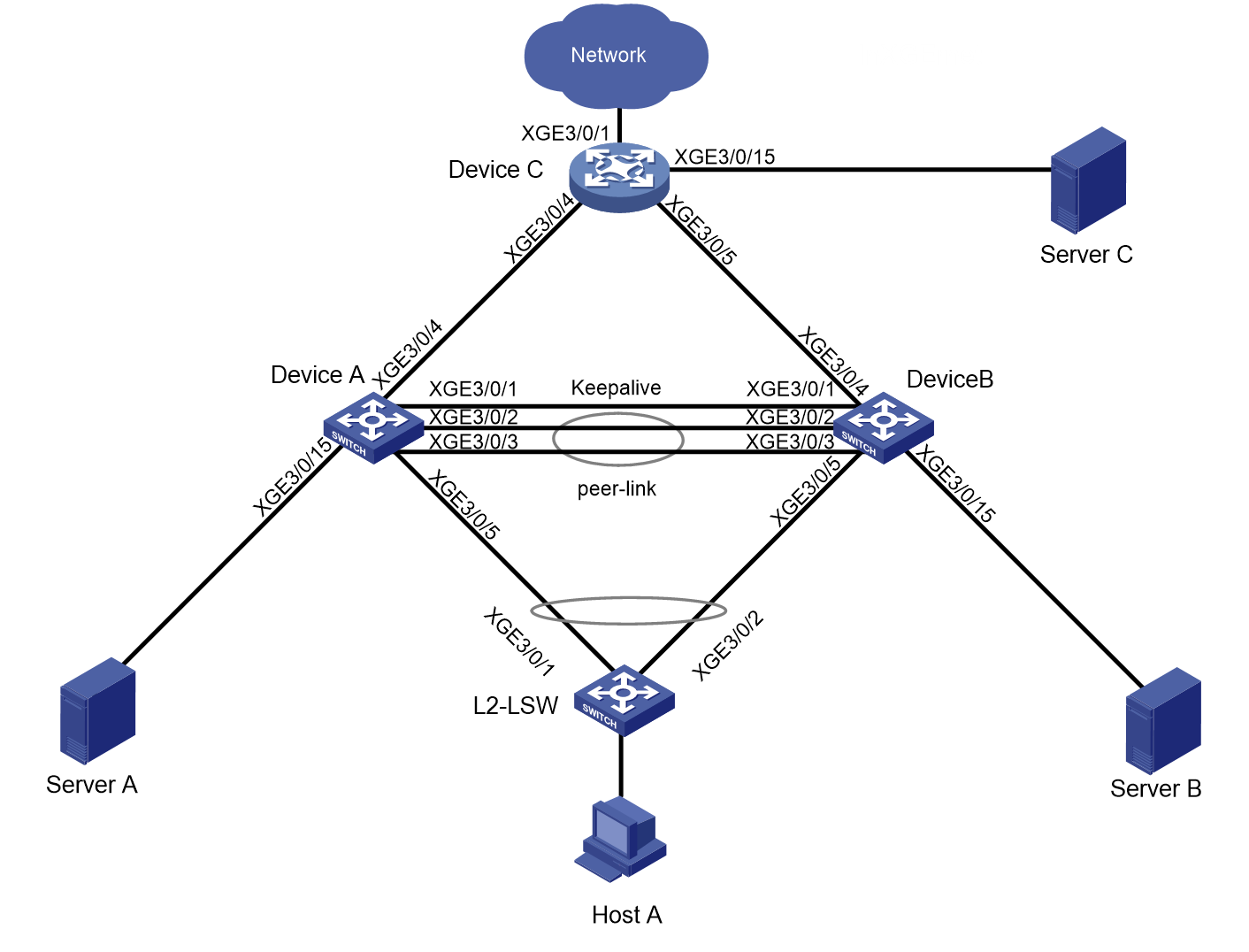
如图1-1所示:
· Device A和Device B组成M-LAG系统,L2-LSW通过M-LAG接口接入M-LAG系统。
· Device A和Device B为Host A提供M-LAG双活网关接入。
· Device A、Device B通过等价路由接入到上行设备Device C。
由于用户对服务器的入网需求,现需要:
· Host A与Network之间IPv4、IPv6双栈网络互通。
· Host A与Network之间的流量镜像到镜像服务器ServerA/B/C。
· 当M-LAG的两个成员设备有链路故障时,各业务仍然互通。
图1-1 M-LAG镜像组网图
|
设备 |
接口 |
IP地址 |
接口说明及对接设备和接口 |
|
Device A |
LoopBack 0 |
3.3.3.3/32 2000::3:3:3:3/128 |
环回口地址 Router id |
|
XGE 3/0/5 |
- |
L2-LSW: XGE3/0/1 M-LAG接口 |
|
|
XGE 3/0/15 |
-- |
Server A |
|
|
XGE 3/0/4 |
32.1.1.1/24 32::1/64 |
Device C: XGE 3/0/4 |
|
|
XGE 3/0/1 |
21.1.1.1/24 |
Device B: XGE 3/0/1 Keepalive链路 |
|
|
XGE 3/0/2 |
- |
Device B: XGE 3/0/2 peer-link接口 |
|
|
XGE 3/0/3 |
- |
Device B: XGE 3/0/3 peer-link接口 |
|
|
Vlan 100 |
100.1.1.1/24 100::1/64 |
双活网关 |
|
|
Vlan 101 |
101.1.1.1/24 101::1/64 |
两台M-LAG设备互连的三层链路,用于东西向流量转发,或南北向流量逃生,三层远程镜像流量逃生 |
|
|
Device B |
LoopBack 0 |
4.4.4.4/32 2000::4:4:4:4/128 |
环回口地址 Router id |
|
XGE 3/0/5 |
- |
L2-LSW: XGE3/0/2 M-LAG接口 |
|
|
XGE 3/0/4 |
33.1.1.1/24 33::1/64 |
Device C: XGE 3/0/5 |
|
|
XGE 3/0/15 |
-- |
Server B |
|
|
XGE 3/0/1 |
21.1.1.2/24 |
Device A: XGE 3/0/1 Keepalive链路 |
|
|
XGE 3/0/2 |
- |
Device A: XGE 3/0/2 peer-link接口 |
|
|
XGE 3/0/3 |
- |
Device A: XGE 3/0/3 peer-link接口 |
|
|
Vlan 100 |
100.1.1.1/24 100::1/64 |
双活网关 |
|
|
Vlan 101 |
101.1.1.2/24 101::2/64 |
两台M-LAG设备互连的三层链路,用于东西向流量转发,或南北向流量逃生,三层远程镜像流量逃生 |
|
|
Device C |
LoopBack 0 |
5.5.5.5/32 2000::5:5:5:5/128 |
环回口地址 Router id |
|
XGE 3/0/1 |
22.1.1.1/24 22::1/64 |
Network 1 |
|
|
XGE 3/0/4 |
32.1.1.2/24 32::2/64 |
Device A: XGE 3/0/4 |
|
|
XGE 3/0/5 |
33.1.1.2/24 33::2/64 |
Device B: XGE 3/0/4 |
|
|
XGE 3/0/15 |
2.1.1.1/24 |
Server C |
|
|
L2-LSW |
XGE 3/0/1 |
- |
Device A: XGE 3/0/5 M-LAG接口 |
|
XGE 3/0/2 |
- |
Device B: XGE 3/0/5 M-LAG接口 |
|
|
XGE 3/0/3 |
-- |
Host A |
|
|
Host A |
- |
100.1.1.100/24 100::100/64 |
L2-LSW: XGE 3/0/3 |
|
Network 1 |
- |
22.1.1.100/24 22::100/64 |
|
|
Server C |
|
2.1.1.2/24 |
Device C: XGE 3/0/15 |
![]()
请在适用软件版本的基础上安装当前最新补丁。
表1-1 配套设备及使用版本一
|
设备 |
软件版本 |
|
S10500、S10500X、S7600、S7600-X、S7600E-X、S7500X、S7500E |
R7625及以上的版本 |
|
S12500G-AF(T系列单板) |
R7625及以上的版本 |
表1-2 配套设备及使用版本二
|
设备 |
软件版本 |
|
S12500G-AF(S系列单板) |
R8054P04及以上的版本 |
|
S10500X-G、S7500X-G |
R7754P04及以上的版本 |
|
S5590XP-HI-G |
R7754P04及以上的版本 |
· Device A、Device B配置M-LAG,为Host A提供双活网关接入;
· Host A通过L2-LSW双上行接入网络,并在HostA上配置Vlan100的IP作为网关地址;
· Server A、Server B、Server C为镜像服务器;
· Device A、Device B通过等价路由接入到上行设备Device C;
· Device A、Device B之间配置OSPF/OSPFv3邻居,作为逃生链路(上行口故障时,三层远程镜像报文、正常业务可以通过peer-link链路进行逃生);
· IPv4和IPv6网络配置同时存在;
配置前设备的所有参数均采用出厂时的缺省配置。如果您已经对设备进行了配置,为了保证配置效果,请确认现有配置和以下配置不冲突。
VLAN流镜像/全局流镜像仅支持入方向镜像。
Peer-Link接口不支持作为镜像目的端口。
|
Device A |
Device B |
命令说明 |
注意事项 |
|
m-lag system-mac 2-2-2 |
m-lag system-mac 2-2-2 |
配置M-LAG系统MAC地址 |
同一分布式聚合组中,所有M-LAG设备的系统MAC地址必须相同 |
|
m-lag system-number 1 |
m-lag system-number 2 |
配置M-LAG系统编号 |
同一分布式聚合组中的M-LAG设备应配置不同的系统编号 |
|
m-lag system-priority 123 |
m-lag system-priority 123 |
配置M-LAG系统优先级 |
同一分布式聚合组中,所有M-LAG设备的系统优先级必须相同 |
|
m-lag standalone enable |
m-lag standalone enable |
(可选)开启M-LAG设备独立工作模式 |
当M-LAG系统分裂时,为了避免M-LAG系统中的两台设备都作为主设备转发流量的情况,可以在M-LAG系统分裂前配置本功能。 |
|
m-lag restore-delay 300 |
m-lag restore-delay 300 |
配置设备作为从设备加入分布式聚合系统时进行MAC地址表项等信息同步的最大时间 |
- |
|
m-lag keepalive ip destination 21.1.1.2 source 21.1.1.1 |
m-lag keepalive ip destination 21.1.1.1 source 21.1.1.2 |
配置Keepalive报文的目的IPv4地址和源IPv4地址 |
- |
|
interface Ten-gigabitethernetE3/0/1 |
interface Ten-gigabitethernetE3/0/1 |
Keepalive链路接口 |
- |
|
port link-mode route |
port link-mode route |
配置Keepalive链路接口工作在三层模式 |
- |
|
ip address 21.1.1.1 24 |
ip address 21.1.1.2 24 |
配置Keepalive报文的源IPv4地址 |
- |
|
quit |
quit |
退回到系统模式 |
- |
|
m-lag mad exclude interface Ten-gigabitethernetE3/0/1 |
m-lag mad exclude interface Ten-gigabitethernetE3/0/1 |
配置Keepalive链路接口为M-LAG保留接口 |
- |
|
interface bridge-aggregation 1 |
interface bridge-aggregation 1 |
创建以太网聚合接口 |
用作peer-link接口 |
|
link-aggregation mode dynamic |
link-aggregation mode dynamic |
配置用作PeerLink的聚合口工作在动态聚合模式 |
- |
|
quit |
quit |
退回到系统模式 |
- |
|
interface range Ten-gigabitethernetE 3/0/2 Ten-gigabitethernetE 3/0/3 |
interface range Ten-gigabitethernetE 3/0/2 Ten-gigabitethernetE 3/0/3 |
进入物理端口组视图 |
- |
|
port link-aggregation group 1 |
port link-aggregation group 1 |
peer-link链路物理端口加入IPL聚合组 |
- |
|
quit |
quit |
退回到系统模式 |
- |
|
interface bridge-aggregation 1 |
interface bridge-aggregation 1 |
进入以太网聚合接口视图 |
- |
|
port m-lag peer-link 1 |
port m-lag peer-link 1 |
配置聚合口1为peer-link接口 |
- |
|
undo mac-address static source-check enable |
undo mac-address static source-check enable |
关闭报文入接口与静态MAC地址表项匹配检查功能,避免跨peer-link链路三层转发的流量不通 |
- |
|
quit |
quit |
退回到系统模式 |
- |
|
lldp global enable |
lldp global enable |
使能全局LLDP |
- |
|
Device A |
Device B |
命令说明 |
注意事项 |
|
interface bridge-aggregation 2 |
interface bridge-aggregation 2 |
创建连接L2-LSW的以太网聚合接口 |
- |
|
link-aggregation mode dynamic |
link-aggregation mode dynamic |
配置连接L2-LSW的聚合组工作在动态聚合模式 |
- |
|
port m-lag group 1 |
port m-lag group 1 |
配置聚合口2加入M-LAG组1 |
- |
|
port lacp system-priority 100 |
port lacp system-priority 101 |
配置lacp优先级,使得脑裂时只选中高优先级成员口 |
- |
|
quit |
quit |
退回到系统模式 |
- |
|
interface Ten-gigabitethernetE 3/0/5 |
interface Ten-gigabitethernetE 3/0/5 |
进入M-LAG设备连接L2-LSW的物理端口视图 |
- |
|
port link-aggregation group 2 |
port link-aggregation group 2 |
加入聚合组 |
- |
|
quit |
quit |
退回到系统模式 |
- |
|
Device A |
Device B |
命令说明 |
注意事项 |
|
router id 3.3.3.3 |
router id 4.4.4.4 |
配置Router ID |
- |
|
ospf 1 |
ospf 1 |
使能OSPF |
- |
|
import-route direct |
import-route direct |
引入直连路由 |
- |
|
area 0 |
area 0 |
配置区域0 |
- |
|
quit |
quit |
退回到OSPF视图 |
- |
|
quit |
quit |
退回到系统模式 |
- |
|
ospfv3 1 |
ospfv3 1 |
使能OSPFv3 |
- |
|
router-id 3.3.3.3 |
router-id 4.4.4.4 |
配置router id |
- |
|
import-route direct |
import-route direct |
引入直连路由 |
- |
|
area 0 |
area 0 |
配置区域0 |
- |
|
quit |
quit |
退回到OSPFv3视图 |
- |
|
quit |
quit |
退回到系统模式 |
- |
|
interface Loopback 0 |
interface Loopback 0 |
配置环回口 |
- |
|
ip address 3.3.3.3 255.255.255.255 |
ip address 4.4.4.4 255.255.255.255 |
配置环回口IPv4地址 |
- |
|
ospf 1 area 0 |
ospf 1 area 0 |
环回口使能OSPF |
- |
|
ipv6 address 2000::3:3:3:3/128 |
ipv6 address 2000::4:4:4:4/128 |
配置环回口IPv6地址 |
- |
|
ospfv3 1 area 0 |
ospfv3 1 area 0 |
环回口使能OSPFv3 |
- |
|
quit |
quit |
退回到系统模式 |
- |
|
vlan 101 |
vlan 101 |
创建VLAN 101 |
- |
|
quit |
quit |
退回到系统模式 |
- |
|
interface vlan-interface 101 |
interface vlan-interface 101 |
创建接口Vlan-interface101 |
两台M-LAG设备互连的三层接口,用于东西向流量转发,或逃生链路(上行口故障时,三层远程镜像报文、正常业务可以通过peer-link链路进行逃生) |
|
ip address 101.1.1.1 255.255.255.0 |
ip address 101.1.1.2 255.255.255.0 |
配置接口Vlan-interface101的IPv4地址 |
- |
|
ospf 1 area 0 |
ospf 1 area 0 |
接口使能OSPF |
- |
|
ospf network-type p2p |
ospf network-type p2p |
配置OSPF网络类型为P2P |
|
|
ipv6 address 101::1 64 |
ipv6 address 101::2 64 |
配置接口Vlan-interface101的IPv6地址 |
- |
|
ospfv3 1 area 0 |
ospfv3 1 area 0 |
接口使能OSPFv3 |
- |
|
ospfv3 network-type p2p |
ospfv3 network-type p2p |
配置OSPFv3网络类型为P2P |
|
|
quit |
quit |
退回到系统模式 |
- |
|
M-LAG mad exclude interface Vlan-interface 101 |
M-LAG mad exclude interface Vlan-interface 101 |
配置VLAN接口为M-LAG保留接口 |
- |
|
Device A |
Device B |
命令说明 |
注意事项 |
|
vlan 100 |
vlan 100 |
创建VLAN 100 |
- |
|
quit |
quit |
退回到系统模式 |
- |
|
interface bridge-aggregation 2 |
interface bridge-aggregation 2 |
进入以太网聚合接口 |
- |
|
port link-type trunk |
port link-type trunk |
配置二层聚合接口2为Trunk端口 |
- |
|
port trunk permit vlan 100 |
port trunk permit vlan 100 |
允许VLAN 100的报文通过 |
- |
|
undo port trunk permit vlan 1 |
undo port trunk permit vlan 1 |
不允许VLAN 1的报文通过 |
- |
|
quit |
quit |
退回到系统模式 |
- |
|
interface vlan-interface 100 |
interface vlan-interface 100 |
创建接口Vlan-interface100 |
- |
|
ip address 100.1.1.1 24 |
ip address 100.1.1.1 24 |
配置接口Vlan-interface100的IPv4地址 |
使其作为IPv4双活网关 |
|
ipv6 address 100::1 64 |
ipv6 address 100::1 64 |
配置接口Vlan-interface100的IPv6地址 |
使其作为IPv6双活网关 |
|
mac-address 0002-2222-2222 |
mac-address 0002-2222-2222 |
配置接口Vlan-interface100的MAC地址 |
- |
|
quit |
quit |
退回到系统模式 |
- |
|
m-lag mad exclude interface Vlan-interface100 |
m-lag mad exclude interface Vlan-interface100 |
配置接口Vlan-interface100为M-LAG保留接口 |
M-LAG接口上的VLAN接口需要配置为保留接口,以避免M-LAG设备间同步表项时,因VLAN接口处于M-LAG MAD DOWN状态,ARP/ND表项无法同步,影响流量转发 |
|
Device A |
Device B |
命令说明 |
注意事项 |
|
interface Ten-gigabitethernetE 3/0/4 |
interface Ten-gigabitethernetE 3/0/4 |
进入以太网接口视图 |
- |
|
port link-mode route |
port link-mode route |
配置互连端口为路由口 |
- |
|
ip address 32.1.1.1 24 |
ip address 33.1.1.1 24 |
配置IPv4地址 |
- |
|
ospf 1 area 0 |
ospf 1 area 0 |
使能该接口的OSPF功能 |
- |
|
ospf network-type p2p |
ospf network-type p2p |
配置OSPF网络类型为P2P |
- |
|
ipv6 address 32::1 64 |
ipv6 address 33::1 64 |
配置IPv6地址 |
- |
|
ospfv3 1 area 0 |
ospfv3 1 area 0 |
使能该接口的OSPFv3功能 |
- |
|
ospfv3 network-type p2p |
ospfv3 network-type p2p |
配置OSPFv3网络类型为P2P |
- |
|
quit |
quit |
退回到系统模式 |
- |
|
Device C |
命令说明 |
注意事项 |
|
router id 5.5.5.5 |
配置Router ID |
- |
|
ospf 1 |
使能OSPF |
- |
|
import-route direct |
引入直连路由 |
- |
|
area 0 |
配置区域0 |
- |
|
quit |
退回到OSPF视图 |
- |
|
quit |
退回到系统模式 |
- |
|
ospfv3 1 |
使能OSPFv3 |
- |
|
router-id 5.5.5.5 |
配置router id |
- |
|
import-route direct |
引入直连路由 |
- |
|
area 0 |
配置区域0 |
- |
|
quit |
退回到OSPFv3视图 |
- |
|
quit |
退回到系统模式 |
- |
|
interface Loopback 0 |
配置环回口 |
- |
|
ip address 5.5.5.5 255.255.255.255 |
配置环回口IPv4地址 |
- |
|
ospf 1 area 0.0.0.0 |
环回口使能OSPF |
- |
|
ipv6 address 2000::5:5:5:5/128 |
配置环回口IPv6地址 |
- |
|
ospfv3 1 area 0.0.0.0 |
环回口使能OSPFv3 |
- |
|
quit |
退回到系统模式 |
- |
|
interface Ten-gigabitethernetE 3/0/4 |
进入以太网接口视图 |
- |
|
port link-mode route |
配置互连端口为路由口 |
|
|
ip address 32.1.1.1 24 |
配置IPv4地址 |
|
|
ospf 1 area 0 |
使能该接口的OSPF功能 |
- |
|
ospf network-type p2p |
配置OSPF网络类型为P2P |
|
|
ipv6 address 32::1 64 |
配置IPv6地址 |
- |
|
ospfv3 1 area 0 |
使能该接口的OSPFv3功能 |
- |
|
ospfv3 network-type p2p |
配置OSPFv3网络类型为P2P |
|
|
quit |
退回到系统模式 |
- |
|
interface Ten-gigabitethernetE 3/0/5 |
进入以太网接口视图 |
- |
|
port link-mode route |
配置互连端口为路由口 |
|
|
ip address 33.1.1.1 24 |
配置IPv4地址 |
|
|
ospf 1 area 0 |
使能该接口的OSPF功能 |
|
|
ipv6 address 33::1 64 |
配置IPv6地址 |
|
|
ospfv3 1 area 0 |
使能该接口的OSPFv3功能 |
|
|
quit |
退回到系统模式 |
|
|
lldp global enable |
使能全局LLDP |
- |
|
Device C |
命令说明 |
注意事项 |
|
interface Ten-gigabitethernetE 3/0/1 |
进入以太网接口视图 |
- |
|
port link-mode route |
配置Device C与Network互联口为路由口 |
- |
|
ip address 22.1.1.1 255.255.255.0 |
配置Network IPv4地址 |
- |
|
ipv6 address 22::1/64 |
配置Network IPv4地址 |
- |
|
quit |
退回到系统模式 |
- |
|
Device C |
命令说明 |
注意事项 |
|
vlan 2 |
配置镜像服务器互连VLAN |
- |
|
quit |
退回到系统模式 |
- |
|
interface Ten-gigabitethernetE 3/0/15 |
进入以太网接口视图 |
- |
|
port access vlan 2 |
配置Device C与镜像服务器的互连VLAN |
- |
|
quit |
退回到系统模式 |
- |
|
interface Vlan-interface2 |
配置Device C与镜像服务器的互连VLAN接口 |
- |
|
ip address 2.1.1.1 255.255.255.0 |
配置IPv4地址 |
- |
|
quit |
退回到系统模式 |
- |
|
L2-LSW |
命令说明 |
注意事项 |
|
vlan 100 |
创建VLAN |
- |
|
quit |
退回到系统模式 |
|
|
interface bridge-aggregation 2 |
创建连接M-LAG的以太网聚合接口 |
- |
|
link-aggregation mode dynamic |
配置连接M-LAG的聚合组工作在动态聚合模式 |
- |
|
quit |
退回到系统模式 |
- |
|
interface Range Ten-gigabitethernetE 3/0/1 to Ten-gigabitethernetE 3/0/2 |
进入L2-LSW设备连接M-LAG的物理端口视图 |
- |
|
port link-aggregation group 2 |
加入聚合组 |
- |
|
quit |
退回到系统模式 |
- |
|
interface bridge-aggregation 2 |
进入连接M-LAG的以太网聚合接口 |
- |
|
port access vlan 100 |
允许指定VLAN的报文通过 |
- |
|
quit |
退回到系统模式 |
- |
|
lldp global enable |
使能全局LLDP |
- |
|
L2-LSW |
命令说明 |
注意事项 |
|
interface Ten-gigabitethernetE 3/0/3 |
进入以太网接口视图 |
- |
|
port access vlan 100 |
允许VLAN 100的报文通过L2-LSW连接Host的接口 |
- |
|
quit |
退回到系统模式 |
- |
配置端口镜像到本地一个镜像服务器(Device A、Device B独立配置)
配置端口流镜像到本地镜像服务器(Device A、Device B独立配置)
配置VLAN流镜像到本地镜像服务器(Device A、Device B独立配置)
配置全局流镜像到本地镜像服务器(Device A、Device B独立配置)
配置端口镜像到三层远程镜像服务器(Device A、Device B独立配置)(适用于配套设备及使用版本一)
配置端口镜像到三层远程镜像服务器(Device A、Device B独立配置)(适用于配套设备及使用版本二)
配置端口流镜像到三层远程镜像服务器(Device A、Device B独立配置)
|
Device A |
Device B |
命令说明 |
|
mirroring-group 1 local |
mirroring-group 1 local |
配置本地端口镜像组 |
|
mirroring-group 1 mirroring-port Ten-GigabitEthernet 3/0/5 both |
mirroring-group 1 mirroring-port Ten-GigabitEthernet 3/0/5 both |
配置镜像源端口 |
|
mirroring-group 1 monitor-port Ten-GigabitEthernet 3/0/15 |
mirroring-group 1 monitor-port Ten-GigabitEthernet 3/0/15 |
配置镜像目的端口 |
|
Device A |
Device B |
命令说明 |
|
acl number 3000 |
acl number 3000 |
创建ACL 3000 |
|
rule permit tcp source 100.1.1.100 0.0.0.0 |
rule permit tcp source 100.1.1.100 0.0.0.0 |
配置入方向IPv4流镜像规则 |
|
quit |
quit |
返回系统视图 |
|
acl number 3001 |
acl number 3001 |
创建ACL 3001 |
|
rule permit tcp destination 100.1.1.100 0.0.0.0 |
rule permit tcp destination 100.1.1.100 0.0.0.0 |
配置出方向IPv4流镜像规则 |
|
quit |
quit |
-- |
|
acl ipv6 number 3000 |
acl ipv6 number 3000 |
创建IPv6 ACL 3000 |
|
rule permit tcp source 100::100 128 |
rule permit tcp source 100::100 128 |
配置入方向IPv6流镜像规则 |
|
quit |
quit |
返回系统视图 |
|
acl ipv6 number 3001 |
acl ipv6 number 3001 |
创建IPv6 ACL 3001 |
|
rule permit tcp destination 100::100 128 |
rule permit tcp destination 100::100 128 |
配置出方向IPv6流镜像规则 |
|
quit |
quit |
返回系统视图 |
|
traffic classifier test-ipv4-in |
traffic classifier test-ipv4-in |
配置入方向IPv4业务流分类 |
|
if-match acl 3000 |
if-match acl 3000 |
匹配入方向流镜像ACL |
|
quit |
quit |
返回系统视图 |
|
traffic classifier test-ipv4-out |
traffic classifier test-ipv4-out |
配置出方向IPv4业务流分类 |
|
if-match acl 3001 |
if-match acl 3001 |
匹配出方向流镜像ACL |
|
quit |
quit |
返回系统视图 |
|
traffic classifier test-ipv6-in |
traffic classifier test-ipv6-in |
配置入方向IPv6业务流分类 |
|
if-match acl ipv6 3000 |
if-match acl ipv6 3000 |
匹配入方向流镜像ACL |
|
quit |
quit |
返回系统视图 |
|
traffic classifier test-ipv6-out |
traffic classifier test-ipv6-out |
配置出方向IPv6业务流分类 |
|
if-match acl ipv6 3001 |
if-match acl ipv6 3001 |
匹配出方向流镜像ACL |
|
quit |
quit |
返回系统视图 |
|
traffic behavior mir |
traffic behavior mir |
配置流镜像动作 |
|
mirror-to interface Ten-gigabitethernet 3/0/15 |
mirror-to interface Ten-gigabitethernet 3/0/15 |
镜像到镜像服务器 |
|
quit |
quit |
返回系统视图 |
|
qos policy test-in |
qos policy test-in |
创建入方向流镜像QoS策略 |
|
classifier test-ipv4-in behavior mir |
classifier test-ipv4-in behavior mir |
配置入方向IPv4业务CB对 |
|
classifier test-ipv6-in behavior mir |
classifier test-ipv6-in behavior mir |
配置入方向IPv6业务CB对 |
|
quit |
quit |
返回系统视图 |
|
qos policy test-out |
qos policy test-out |
创建出方向流镜像QoS策略 |
|
classifier test-ipv4-out behavior mir |
classifier test-ipv4-out behavior mir |
配置出方向IPv4业务CB对 |
|
classifier test-ipv6-out behavior mir |
classifier test-ipv6-out behavior mir |
配置出方向IPv6业务CB对 |
|
quit |
quit |
返回系统视图 |
|
interface Ten-gigabitethernet 3/0/5 |
interface Ten-gigabitethernet 3/0/5 |
需要进行流镜像的源端口 |
|
qos apply policy test-in inbound |
qos apply policy test-in inbound |
配置入方向流镜像 |
|
qos apply policy test-out outbound |
qos apply policy test-out outbound |
配置出方向流镜像 |
|
quit |
quit |
返回系统视图 |
|
Device A |
Device B |
命令说明 |
|
acl number 3000 |
acl number 3000 |
创建ACL 3000 |
|
rule permit tcp source 100.1.1.100 0.0.0.0 |
rule permit tcp source 100.1.1.100 0.0.0.0 |
配置入方向IPv4流镜像规则 |
|
quit |
quit |
返回系统视图 |
|
acl ipv6 number 3000 |
acl ipv6 number 3000 |
创建IPv6 ACL 3000 |
|
rule permit tcp source 100::100 128 |
rule permit tcp source 100::100 128 |
配置入方向IPv6流镜像规则 |
|
quit |
quit |
返回系统视图 |
|
traffic classifier test-ipv4-in |
traffic classifier test-ipv4-in |
配置入方向IPv4业务流分类 |
|
if-match acl 3000 |
if-match acl 3000 |
匹配入方向流镜像ACL |
|
quit |
quit |
返回系统视图 |
|
traffic classifier test-ipv6-in |
traffic classifier test-ipv6-in |
配置入方向IPv6业务流分类 |
|
if-match acl ipv6 3000 |
if-match acl ipv6 3000 |
匹配入方向流镜像ACL |
|
quit |
quit |
返回系统视图 |
|
traffic behavior mir |
traffic behavior mir |
配置流镜像动作 |
|
mirror-to interface Ten-gigabitethernet 3/0/15 |
mirror-to interface Ten-gigabitethernet 3/0/15 |
镜像到镜像服务器 |
|
quit |
quit |
返回系统视图 |
|
qos policy test-in |
qos policy test-in |
创建入方向流镜像QoS策略 |
|
classifier test-ipv4-in behavior mir |
classifier test-ipv4-in behavior mir |
配置入方向IPv4业务CB对 |
|
classifier test-ipv6-in behavior mir |
classifier test-ipv6-in behavior mir |
配置入方向IPv6业务CB对 |
|
quit |
quit |
返回系统视图 |
|
qos vlan-policy test-in vlan 100 inbound |
qos vlan-policy test-in vlan 100 inbound |
配置入方向VLAN流镜像 |
|
Device A |
Device B |
命令说明 |
|
acl number 3000 |
acl number 3000 |
创建ACL 3000 |
|
rule permit tcp source 100.1.1.100 0.0.0.0 |
rule permit tcp source 100.1.1.100 0.0.0.0 |
配置入方向IPv4流镜像规则 |
|
quit |
quit |
返回系统视图 |
|
acl ipv6 number 3000 |
acl ipv6 number 3000 |
创建IPv6 ACL 3000 |
|
rule permit tcp source 100::100 128 |
rule permit tcp source 100::100 128 |
配置入方向IPv6流镜像规则 |
|
quit |
quit |
返回系统视图 |
|
traffic classifier test-ipv4-in |
traffic classifier test-ipv4-in |
配置入方向IPv4业务流分类 |
|
if-match acl 3000 |
if-match acl 3000 |
匹配入方向流镜像ACL |
|
quit |
quit |
返回系统视图 |
|
traffic classifier test-ipv6-in |
traffic classifier test-ipv6-in |
配置入方向IPv6业务流分类 |
|
if-match acl ipv6 3000 |
if-match acl ipv6 3000 |
匹配入方向流镜像ACL |
|
quit |
quit |
返回系统视图 |
|
traffic behavior mir |
traffic behavior mir |
配置流镜像动作 |
|
mirror-to interface Ten-gigabitethernet 3/0/15 |
mirror-to interface Ten-gigabitethernet 3/0/15 |
镜像到镜像服务器 |
|
qos policy test-in |
qos policy test-in |
创建入方向流镜像QoS策略 |
|
classifier test-ipv4-in behavior mir |
classifier test-ipv4-in behavior mir |
配置入方向IPv4业务CB对 |
|
classifier test-ipv6-in behavior mir |
classifier test-ipv6-in behavior mir |
配置入方向IPv6业务CB对 |
|
quit |
quit |
返回系统视图 |
|
qos apply policy test-in global inbound |
qos apply policy test-in global inbound |
配置入方向全局流镜像 |
|
Device A |
Device B |
命令说明 |
|
service-loopback group 1 type tunnel |
service-loopback group 1 type tunnel |
创建业务环回组1,并配置服务类型为Tunnel |
|
interface Ten-gigabitethernet 3/0/8 |
interface Ten-gigabitethernet 3/0/8 |
远程镜像业务环回端口(该接口为任意未使用接口) |
|
port service-loopback group 1 |
port service-loopback group 1 |
加入业务环回组 |
|
quit |
quit |
返回系统视图 |
|
interface tunnel 1 mode gre |
interface tunnel 1 mode gre |
创建GRE模式的Tunnel接口 |
|
ip address 50.1.1.1 24 |
ip address 50.2.1.1 24 |
配置IP地址 |
|
source LoopBack0 |
source LoopBack0 |
指定源地址 |
|
destination 5.5.5.5 |
destination 5.5.5.5 |
指定目的地址 |
|
quit |
quit |
返回系统视图 |
|
mirroring-group 1 local |
mirroring-group 1 local |
配置本地镜像组 |
|
mirroring-group 1 mirroring-port Ten-GigabitEthernet 3/0/5 both |
mirroring-group 1 mirroring-port Ten-GigabitEthernet 3/0/5 both |
配置镜像组的源端口 |
|
mirroring-group 1 monitor-port tunnel 1 |
mirroring-group 1 monitor-port tunnel 1 |
配置镜像组的目的端口 |
|
Device C |
命令说明 |
|
service-loopback group 1 type tunnel |
创建业务环回组1,并配置服务类型为Tunnel |
|
interface Ten-gigabitethernet 3/0/8 |
远程镜像业务环回端口(该接口为任意未使用接口) |
|
port service-loopback group 1 |
加入业务环回组 |
|
quit |
返回系统视图 |
|
interface tunnel 1 mode gre |
创建GRE模式的Tunnel接口 |
|
ip address 50.1.1.2 24 |
配置IP地址 |
|
source LoopBack0 |
指定源地址 |
|
destination 3.3.3.3 |
指定Device A的目的地址 |
|
quit |
返回系统视图 |
|
interface tunnel 2 mode gre |
创建GRE模式的Tunnel接口 |
|
ip address 50.2.1.2 24 |
配置IP地址 |
|
source LoopBack0 |
指定源地址 |
|
destination 4.4.4.4 |
指定Device B的目的地址 |
|
quit |
返回系统视图 |
|
mirroring-group 1 local |
配置本地镜像组 |
|
mirroring-group 1 mirroring-port Ten-GigabitEthernet 3/0/4 Ten-GigabitEthernet 3/0/5 inbound |
配置镜像组的源端口 |
|
mirroring-group 1 monitor-port Ten-GigabitEthernet 3/0/15 |
配置镜像组的目的端口 |
|
acl number 3000 |
为了防止GRE封装的镜像报文在Device C上做除镜像外的其他用途,需要配置ACL规则,对此类报文进行过滤 |
|
rule deny gre source 3.3.3.3 0 destination 5.5.5.5 0 |
匹配GRE封装的镜像报文 |
|
rule deny gre source 4.4.4.4 0 destination 5.5.5.5 0 |
匹配GRE封装的镜像报文 |
|
quit |
返回系统视图 |
|
interface range Ten-gigabitethernet 3/0/4 to Ten-gigabitethernet 3/0/5 |
报文源端口 |
|
packet-filter 3000 inbound |
过滤GRE封装的镜像报文 |
|
quit |
返回系统视图 |
|
Device A |
Device B |
命令说明 |
|
mirroring-group 1 local |
mirroring-group 1 local |
配置本地镜像组 |
|
mirroring-group 1 mirroring-port Ten-GigabitEthernet 3/0/5 both |
mirroring-group 1 mirroring-port Ten-GigabitEthernet 3/0/5 both |
配置镜像组的源端口 |
|
mirroring-group 1 monitor-port Ten-GigabitEthernet 3/0/4 destination-ip 2.1.1.2 source-ip 32.1.1.1 |
mirroring-group 1 monitor-port Ten-GigabitEthernet 3/0/4 destination-ip 2.1.1.2 source-ip 33.1.1.1 |
配置镜像组的目的端口 |
|
Device A |
Device B |
命令说明 |
|
acl number 3000 |
acl number 3000 |
创建ACL 3000 |
|
rule permit tcp source 100.1.1.100 0.0.0.0 |
rule permit tcp source 100.1.1.100 0.0.0.0 |
配置入方向IPv4流镜像规则 |
|
quit |
quit |
返回系统视图 |
|
acl number 3001 |
acl number 3001 |
创建ACL 3001 |
|
rule permit tcp destination 100.1.1.100 0.0.0.0 |
rule permit tcp destination 100.1.1.100 0.0.0.0 |
配置出方向IPv4流镜像规则 |
|
quit |
quit |
返回系统视图 |
|
acl ipv6 number 3000 |
acl ipv6 number 3000 |
创建IPv6 ACL 3000 |
|
rule permit tcp source 100::100 128 |
rule permit tcp source 100::100 128 |
配置入方向IPv6流镜像规则 |
|
quit |
quit |
返回系统视图 |
|
acl ipv6 number 3001 |
acl ipv6 number 3001 |
创建IPv6 ACL 3001 |
|
rule permit tcp destination 100::100 128 |
rule permit tcp destination 100::100 128 |
配置出方向IPv6流镜像规则 |
|
quit |
quit |
返回系统视图 |
|
traffic classifier test-ipv4-in |
traffic classifier test-ipv4-in |
配置入方向IPv4业务流分类 |
|
if-match acl 3000 |
if-match acl 3000 |
匹配入方向流镜像ACL |
|
quit |
quit |
返回系统视图 |
|
traffic classifier test-ipv4-out |
traffic classifier test-ipv4-out |
配置出方向IPv4业务流分类 |
|
if-match acl 3001 |
if-match acl 3001 |
匹配出方向流镜像ACL |
|
quit |
quit |
返回系统视图 |
|
traffic classifier test-ipv6-in |
traffic classifier test-ipv6-in |
配置入方向IPv6业务流分类 |
|
if-match acl ipv6 3000 |
if-match acl ipv6 3000 |
匹配入方向流镜像ACL |
|
quit |
quit |
返回系统视图 |
|
traffic classifier test-ipv6-out |
traffic classifier test-ipv6-out |
配置出方向IPv6业务流分类 |
|
if-match acl ipv6 3001 |
if-match acl ipv6 3001 |
匹配出方向流镜像ACL |
|
quit |
quit |
返回系统视图 |
|
traffic behavior mir |
traffic behavior mir |
配置流镜像动作 |
|
mirror-to interface destination-ip 2.1.1.2 source-ip 3.3.3.3 |
mirror-to interface destination-ip 2.1.1.2 source-ip 4.4.4.4 |
镜像到远程镜像服务器 |
|
quit |
quit |
返回系统视图 |
|
qos policy test-in |
qos policy test-in |
创建入方向流镜像QoS策略 |
|
classifier test-ipv4-in behavior mir |
classifier test-ipv4-in behavior mir |
配置入方向IPv4业务CB对 |
|
classifier test-ipv6-in behavior mir |
classifier test-ipv6-in behavior mir |
配置入方向IPv6业务CB对 |
|
quit |
quit |
返回系统视图 |
|
qos policy test-out |
qos policy test-out |
创建出方向流镜像QoS策略 |
|
classifier test-ipv4-out behavior mir |
classifier test-ipv4-out behavior mir |
配置出方向IPv4业务CB对 |
|
classifier test-ipv6-out behavior mir |
classifier test-ipv6-out behavior mir |
配置出方向IPv6业务CB对 |
|
Quit |
quit |
返回系统视图 |
|
interface Ten-gigabitethernet 3/0/5 |
interface Ten-gigabitethernet 3/0/5 |
需要进行流镜像的源端口 |
|
qos apply policy test-in inbound |
qos apply policy test-in inbound |
配置入方向流镜像 |
|
qos apply policy test-out outbound |
qos apply policy test-out outbound |
配置出方向流镜像 |
|
quit |
quit |
返回系统视图 |
流量模型描述表格主要包含以下信息:
· 编号:即流量编号,格式为O-X-XXX。其中,O表示Overrlay流量;X表示协议号,取值包括4(IPv4)和6(IPv6);XXX表示流量序号,从001开始。
· 类型:即流量类型,取值包括已知单播/IPv4、单播/L2等。
· 流量方向:即流量的发送方向,取值包括跨Leaf东西、南北等。
· 流量路径:即流量经过的每个节点。
· 仿真方式:进行本组网测试时,采用的流量仿真方式,一般为测试仪仿真,即采用测试仪模拟服务器发送流量。
· 流量大小:取值包括轻载(仿真流量小于1000条流)和重载(仿真流量大于1000条流)。
|
编号 |
类型 |
流量方向 |
流量路径 |
仿真方式 |
流量大小 |
上墙/LB方式 |
说明 |
|
O-4-001 |
已知单播/IPv4 |
- |
HostA-DeviceA/B-Device C-Network |
测试仪 |
轻载 |
不涉及 |
上行口故障时,远程镜像流量、正常业务可以通过M-LAG设备间三层链路转发 |
|
O-4-002 |
已知单播/IPv4 |
- |
Network-Device C-Device A/B-HostA |
测试仪 |
轻载 |
不涉及 |
|
|
O-6-001 |
已知单播/IPv6 |
- |
HostA-DeviceA/B-Device C-Network |
测试仪 |
轻载 |
不涉及 |
|
|
O-6-002 |
已知单播/IPv6 |
- |
Network-Device c-Device A/B-HostA |
测试仪 |
轻载 |
不涉及 |
镜像到本地镜像服务器的各种方式,在单点故障情况下,镜像功能本身无影响,故障时如果业务端口无流量,则镜像服务器未能接收报文。
表1-3 链路单点故障测试情况表
|
设备 |
故障类型 |
端口镜像到本地一个服务器 |
端口流镜像到本地镜像服务器 |
VLAN流镜像到本地镜像服务器 |
全局流镜像到本地镜像服务器 |
备注 |
|
Device A |
M-LAG成员链路单点故障 |
镜像功能无影响 |
镜像功能无影响 |
镜像功能无影响 |
镜像功能无影响 |
|
|
M-LAG成员链路单点故障恢复 |
镜像功能无影响 |
镜像功能无影响 |
镜像功能无影响 |
镜像功能无影响 |
|
|
|
上行链路单点故障 |
镜像功能无影响 |
镜像功能无影响 |
镜像功能无影响 |
镜像功能无影响 |
|
|
|
上行链路单点故障恢复 |
镜像功能无影响 |
镜像功能无影响 |
镜像功能无影响 |
镜像功能无影响 |
|
|
|
peer-link链路故障 |
镜像功能无影响 |
镜像功能无影响 |
镜像功能无影响 |
镜像功能无影响 |
|
|
|
peer-link链路故障恢复 |
镜像功能无影响 |
镜像功能无影响 |
镜像功能无影响 |
镜像功能无影响 |
|
|
|
Keepalive链路故障 |
镜像功能无影响 |
镜像功能无影响 |
镜像功能无影响 |
镜像功能无影响 |
|
|
|
Keepalive链路故障恢复 |
镜像功能无影响 |
镜像功能无影响 |
镜像功能无影响 |
镜像功能无影响 |
|
|
|
Keepalive和peer-link链路都故障 |
镜像功能无影响 |
镜像功能无影响 |
镜像功能无影响 |
镜像功能无影响 |
|
|
|
Keepalive和peer-link链路都故障恢复 |
镜像功能无影响 |
镜像功能无影响 |
镜像功能无影响 |
镜像功能无影响 |
|
|
|
重启一台M-LAG设备 |
镜像功能无影响 |
镜像功能无影响 |
镜像功能无影响 |
镜像功能无影响 |
|
|
|
重启的M-LAG设备恢复 |
镜像功能无影响 |
镜像功能无影响 |
镜像功能无影响 |
镜像功能无影响 |
|
|
|
网板故障 |
镜像功能无影响 |
镜像功能无影响 |
镜像功能无影响 |
镜像功能无影响 |
|
|
|
网板恢复 |
镜像功能无影响 |
镜像功能无影响 |
镜像功能无影响 |
镜像功能无影响 |
|
镜像到远程镜像服务器的各种方式,在单点故障情况下,镜像功能本身无影响,故障时如果业务端口无流量,则镜像服务器未能接收报文。
表1-4 链路单点故障测试情况表
|
设备 |
故障类型 |
端口镜像到三层远程镜像服务器 |
流镜像到三层远程镜像服务器 |
备注 |
|
Device A |
M-LAG成员链路单点故障 |
镜像功能无影响 |
镜像功能无影响 |
|
|
M-LAG成员链路单点故障恢复 |
镜像功能无影响 |
镜像功能无影响 |
|
|
|
上行链路单点故障 |
镜像功能无影响 |
镜像功能无影响 |
|
|
|
上行链路单点故障恢复 |
镜像功能无影响 |
镜像功能无影响 |
|
|
|
peer-link链路故障 |
镜像功能无影响 |
镜像功能无影响 |
|
|
|
peer-link链路故障恢复 |
镜像功能无影响 |
镜像功能无影响 |
|
|
|
Keepalive链路故障 |
镜像功能无影响 |
镜像功能无影响 |
|
|
|
Keepalive链路故障恢复 |
镜像功能无影响 |
镜像功能无影响 |
|
|
|
Keepalive和peer-link链路都故障 |
镜像功能无影响 |
镜像功能无影响 |
|
|
|
Keepalive和peer-link链路都故障恢复 |
镜像功能无影响 |
镜像功能无影响 |
|
|
|
重启一台M-LAG设备 |
镜像功能无影响 |
镜像功能无影响 |
|
|
|
重启的M-LAG设备恢复 |
镜像功能无影响 |
镜像功能无影响 |
|
|
|
网板故障 |
镜像功能无影响 |
镜像功能无影响 |
|
|
|
网板恢复 |
镜像功能无影响 |
镜像功能无影响 |
|
表1-5 配置验证命令汇总表
|
Device A |
Device B |
命令说明 |
|
display m-lag summary |
display m-lag summary |
显示分布式聚合系统的接口摘要信息 |
|
display m-lag keepalive |
display m-lag keepalive |
显示分布式聚合Keepalive报文的信息 |
|
display m-lag role |
display m-lag role |
显示分布式聚合设备角色信息 |
|
display m-lag verbose |
display m-lag verbose |
显示分布式聚合系统的接口详细信息 |
|
display mirroring-group |
display mirroring-group |
显示端口镜像配置 |
|
display qos policy interface inbound/outbound |
display qos policy interface inbound/outbound |
显示端口流镜像配置信息 |
|
display qos vlan-policy vlan vlan-id inbound |
display qos vlan-policy vlan vlan-id inbound |
显示VLAN流镜像配置信息 |
|
display qos policy global inbound |
display qos policy global inbound |
显示全局流镜像配置信息 |
# 查看Device A和Device B之间M-LAG系统状态,M-LAG正常建立。
# 显示分布式聚合系统的接口摘要信息,peer-link接口状态均为UP。
<Device A>display m-lag summary
Flags: A -- Aggregate interface down, B -- No peer M-LAG interface configured
C -- Configuration consistency check failed
Peer-link interface: BAGG1
Peer-link interface state (cause): UP
Keepalive link state (cause): UP
M-LAG interface information
M-LAG IF M-LAG group Local state (cause) Peer state Remaining down time(s)
BAGG2 1 UP UP -
<Device B>display m-lag summary
Flags: A -- Aggregate interface down, B -- No peer M-LAG interface configured
C -- Configuration consistency check failed
Peer-link interface: BAGG1
Peer-link interface state (cause): UP
Keepalive link state (cause): UP
M-LAG interface information
M-LAG IF M-LAG group Local state (cause) Peer state Remaining down time(s)
BAGG2 1 UP UP -
# 显示分布式聚合Keepalive报文的信息,Keepalive报文的收发状态均为successful。
<Device A>display m-lag keepalive
Neighbor keepalive link status (cause): Up
Neighbor is alive for: 590 s 830 ms
Keepalive packet transmission status:
Sent: Successful
Received: Successful
Last received keepalive packet information:
Source IP address: 21.1.1.2
Time: 2022/08/01 15:53:17
Action: Accept
M-LAG keepalive parameters:
Destination IP address: 21.1.1.2
Source IP address: 21.1.1.1
Keepalive UDP port : 6400
Keepalive VPN name : N/A
Keepalive interval : 1000 ms
Keepalive timeout : 5 sec
Keepalive hold time: 3 sec
<Device A>
<Device B>disp m-lag keepalive
Neighbor keepalive link status (cause): Up
Neighbor is alive for: 650 s 238 ms
Keepalive packet transmission status:
Sent: Successful
Received: Successful
Last received keepalive packet information:
Source IP address: 21.1.1.1
Time: 2022/08/01 15:59:11
Action: Accept
M-LAG keepalive parameters:
Destination IP address: 21.1.1.1
Source IP address: 21.1.1.2
Keepalive UDP port : 6400
Keepalive VPN name : N/A
Keepalive interval : 1000 ms
Keepalive timeout : 5 sec
Keepalive hold time: 3 sec
# 显示分布式聚合设备角色信息,Device A为Secondary,Device B为Primary。
<Device A>display m-lag role
Effective role information
Factors Local Peer
Effective role Secondary Primary
Initial role None Primary
MAD DOWN state Yes No
Health level 3 0
Role priority 32768 32768
Bridge MAC 0cda-41c5-aab0 0000-fc00-c7fb
Effective role trigger: Peer link calculation
Effective role reason: Single None role
Configured role information
Factors Local Peer
Configured role Secondary Primary
Role priority 32768 32768
Bridge MAC 0cda-41c5-aab0 0000-fc00-c7fb
<Device B>disp m-lag role
Effective role information
Factors Local Peer
Effective role Primary Secondary
Initial role Primary None
MAD DOWN state No Yes
Health level 0 3
Role priority 32768 32768
Bridge MAC 0000-fc00-c7fb 0cda-41c5-aab0
Effective role trigger: Peer link calculation
Effective role reason: Single None role
Configured role information
Factors Local Peer
Configured role Primary Secondary
Role priority 32768 32768
Bridge MAC 0000-fc00-c7fb 0cda-41c5-aab0
# 显示分布式聚合系统的接口详细信息。
<Device A>display m-lag verbose
Flags: A -- Home_Gateway, B -- Neighbor_Gateway, C -- Other_Gateway,
D -- PeerLink_Activity, E -- DRCP_Timeout, F -- Gateway_Sync,
G -- Port_Sync, H -- Expired
Peer-link interface/Peer-link interface ID: BAGG1/1
State: UP
Cause: -
Local DRCP flags/Peer DRCP flags: ABDFG/ABDFG
Local Selected ports (index): XGE3/0/2 (292), XGE3/0/3 (293)
Peer Selected ports indexes: 207, 208
M-LAG interface/M-LAG group ID: BAGG2/1
Local M-LAG interface state: UP
Peer M-LAG interface state: UP
M-LAG group state: UP
Local M-LAG interface down cause: -
Remaining M-LAG DOWN time: -
Local M-LAG interface LACP MAC: Config=N/A, Effective=0002-0002-0002
Peer M-LAG interface LACP MAC: Config=N/A, Effective=0002-0002-0002
Local M-LAG interface LACP priority: Config=32768, Effective=123
Peer M-LAG interface LACP priority: Config=32768, Effective=123
Local DRCP flags/Peer DRCP flags: ABDFG/ABDFG
Local Selected ports (index): XGE3/0/5 (295)
Peer Selected ports indexes: 210
<Device A>
<Device B>disp m-lag verbose
Flags: A -- Home_Gateway, B -- Neighbor_Gateway, C -- Other_Gateway,
D -- PeerLink_Activity, E -- DRCP_Timeout, F -- Gateway_Sync,
G -- Port_Sync, H -- Expired
Peer-link interface/Peer-link interface ID: BAGG1/1
State: UP
Cause: -
Local DRCP flags/Peer DRCP flags: ABDFG/ABDFG
Local Selected ports (index): XGE3/0/2 (207), XGE3/0/3 (208)
Peer Selected ports indexes: 292, 293
M-LAG interface/M-LAG group ID: BAGG2/1
Local M-LAG interface state: UP
Peer M-LAG interface state: UP
M-LAG group state: UP
Local M-LAG interface down cause: -
Remaining M-LAG DOWN time: -
Local M-LAG interface LACP MAC: Config=N/A, Effective=0002-0002-0002
Peer M-LAG interface LACP MAC: Config=N/A, Effective=0002-0002-0002
Local M-LAG interface LACP priority: Config=32768, Effective=123
Peer M-LAG interface LACP priority: Config=32768, Effective=123
Local DRCP flags/Peer DRCP flags: ABDFG/ABDFG
Local Selected ports (index): XGE3/0/5 (210)
Peer Selected ports indexes: 295
# 以Device A上本地端口镜像信息为例。
[Device A]display mirroring-group 1
Mirroring group 1:
Type: Local
Status: Active
Mirroring port:
Ten-GigabitEthernet3/0/5 Both
Monitor port: Ten-GigabitEthernet3/0/15
# 以Device A上端口流镜像信息为例。
[Device A]display qos policy interface te 3/0/5
Interface: Ten-GigabitEthernet3/0/5
Direction: Inbound
Policy: test-in
Classifier: test-ipv4-in
Operator: AND
Rule(s) :
If-match acl 3000
Behavior: mir
Mirroring:
Mirror to the interface: Ten-GigabitEthernet3/0/15
Classifier: test-ipv6-in
Operator: AND
Rule(s) :
If-match acl ipv6 3000
Behavior: mir
Mirroring:
Mirror to the interface: Ten-GigabitEthernet3/0/15
Interface: Ten-GigabitEthernet3/0/5
Direction: Outbound
Policy: test-out
Classifier: test-ipv4-out
Operator: AND
Rule(s) :
If-match acl 3001
Behavior: mir
Mirroring:
Mirror to the interface: Ten-GigabitEthernet3/0/15
Classifier: test-ipv6-out
Operator: AND
Rule(s) :
If-match acl ipv6 3001
Behavior: mir
Mirroring:
Mirror to the interface: Ten-GigabitEthernet3/0/15
# 以Device A上VLAN流镜像信息为例。
[Device A]display qos vlan-policy vlan 100 inbound
Vlan 100
Direction: Inbound
Policy: test-in
Classifier: test-ipv4-in
Operator: AND
Rule(s) :
If-match acl 3000
Behavior: mir
Mirroring:
Mirror to the interface: Ten-GigabitEthernet3/0/15
Classifier: test-ipv6-in
Operator: AND
Rule(s) :
If-match acl ipv6 3000
Behavior: mir
Mirroring:
Mirror to the interface: Ten-GigabitEthernet3/0/15
# 以Device A上全局流镜像信息为例。
[Device A]display qos policy global inbound
Direction: Inbound
Policy: test-in
Classifier: test-ipv4-in
Operator: AND
Rule(s) :
If-match acl 3000
Behavior: mir
Mirroring:
Mirror to the interface: Ten-GigabitEthernet3/0/15
Classifier: test-ipv6-in
Operator: AND
Rule(s) :
If-match acl ipv6 3000
Behavior: mir
Mirroring:
Mirror to the interface: Ten-GigabitEthernet3/0/15
# 以Device A上三层远程端口镜像信息为例。
[Device A]display mirroring-group 1
Mirroring group 1:
Type: Local
Status: Active
Mirroring port:
Ten-GigabitEthernet3/0/5 Both
Monitor port: Tunnel1
[Device A]display interface Tunnel 1
Tunnel1
Current state: UP
Line protocol state: UP
Description: Tunnel1 Interface
Bandwidth: 64 kbps
Maximum transmission unit: 1476
Internet address: 50.1.1.1/24 (Primary)
Tunnel source 3.3.3.3 (LoopBack0), destination 5.5.5.5
Tunnel keepalive disabled
Tunnel TTL 255
Tunnel protocol/transport GRE/IP
GRE key disabled
Checksumming of GRE packets disabled
Last clearing of counters: Never
Last 5 seconds input rate: 0 bytes/sec, 0 bits/sec, 0 packets/sec
Last 5 seconds output rate: 0 bytes/sec, 0 bits/sec, 0 packets/sec
Input: 0 packets, 0 bytes, 0 drops
Output: 0 packets, 0 bytes, 0 drops
# Device C上三层远程端口镜像信息。
[Device C]display mirroring-group 1
Mirroring group 1:
Type: Local
Status: Active
Mirroring port:
Ten-GigabitEthernet3/0/4 Inbound
Ten-GigabitEthernet3/0/5 Inbound
Monitor port: Ten-GigabitEthernet3/0/15
[Device C]display interface Tunnel 1
Tunnel1
Current state: UP
Line protocol state: UP
Description: Tunnel1 Interface
Bandwidth: 64 kbps
Maximum transmission unit: 1476
Internet address: 50.1.1.2/24 (primary)
Tunnel source 5.5.5.5 (LoopBack0), destination 3.3.3.3
Tunnel keepalive disabled
Tunnel TTL 255
Tunnel protocol/transport GRE/IP
GRE key disabled
Checksumming of GRE packets disabled
Last clearing of counters: Never
Last 300 seconds input rate: 0 bytes/sec, 0 bits/sec, 0 packets/sec
Last 300 seconds output rate: 0 bytes/sec, 0 bits/sec, 0 packets/sec
Input: 128712 packets, 16243280 bytes, 2 drops
Output: 0 packets, 0 bytes, 0 drops
# 以Device A上三层远程端口镜像信息为例。
[DeviceA] display mirroring-group all
Mirroring group 1:
Type: Local
Status: Active
Mirroring port:
Ten-GigabitEthernet3/0/5 Both
Monitor port: Ten-GigabitEthernet3/0/4
Encapsulation: Destination IP address 32.1.1.1
Source IP address 2.1.1.2
Destination MAC address 00e0-fc00-5128
# 以Device A上三层远程流镜像信息为例。
[Device A]display qos policy interface Ten-GigabitEthernet 3/0/5
Interface: Ten-GigabitEthernet3/0/5
Direction: Inbound
Policy: test-in
Classifier: test-ipv4-in
Operator: AND
Rule(s) :
If-match acl 3000
Behavior: mir
Mirroring:
Mirror to the interface: Ten-GigabitEthernet3/0/4(dynamic)
Encapsulation: Destination IP address 2.1.1.2
Source IP address 3.3.3.3
Destination-MAC 00e0-fc00-5128
Classifier: test-ipv6-in
Operator: AND
Rule(s) :
If-match acl ipv6 3000
Behavior: mir
Mirroring:
Mirror to the interface: Ten-GigabitEthernet3/0/4(dynamic)
Encapsulation: Destination IP address 2.1.1.2
Source IP address 3.3.3.3
Destination-MAC 00e0-fc00-5128
Interface: Ten-GigabitEthernet3/0/5
Direction: Outbound
Policy: test-out
Classifier: test-ipv4-out
Operator: AND
Rule(s) :
If-match acl 3001
Behavior: mir
Mirroring:
Mirror to the interface: Ten-GigabitEthernet3/0/4(dynamic)
Encapsulation: Destination IP address 2.1.1.2
Source IP address 3.3.3.3
Destination-MAC 00e0-fc00-5128
Classifier: test-ipv6-out
Operator: AND
Rule(s) :
If-match acl ipv6 3001
Behavior: mir
Mirroring:
Mirror to the interface: Ten-GigabitEthernet3/0/4(dynamic)
Encapsulation: Destination IP address 2.1.1.2
Source IP address 3.3.3.3
Destination-MAC 00e0-fc00-5128
升级前的命令行检查,请参见“1.11 验证配置”和以下表格中的命令行。
表1-6 升级前的命令行检查汇总表
|
Device A |
Device B |
命令说明 |
|
display device |
display device |
用来显示分布式聚合系统的接口摘要信息 |
|
display boot-loader |
display boot-loader |
用来显示本次启动和下次启动所采用的启动软件包的名称 |
|
display version |
display version |
用来显示系统版本信息 |
升级设备软件前,请进行如下操作:
(1) 使用display version命令查看设备当前运行的BootWare程序以及启动软件的版本。
(2) 获取新软件的版本发布说明书,了解新软件的版本号、软件大小以及和当前运行的BootWare程序以及Comware软件的兼容性。
(3) 通过版本发布说明书了解将安装的软件包是否需要License。如果需要,查看设备上是否有对应的有效的License。如果没有,请先安装License。否则,会导致软件包安装失败。
(4) 使用dir命令查看存储介质是否有足够的空间存储新的软件。如果存储空间不足,可使用delete命令删除一些暂时不用的文件。请保证系统中所有的主控板都有足够的存储空间。
(5) Device A设备与Device B设备组成M-LAG系统后:
a. 检查Device A设备的LLDP邻居,得到Device A设备上所有接口的LLDP状态信息。
b. Device A设备上除peer-link接口和Keepalive接口之外,所有连接到其他设备的接口均手动shutdown。
c. 将Device A设备所有进出的流量都切换到Device B设备上面。
(6) 保存Device A设备的配置,使用FTP、TFTP方式将新软件包下载到任一文件系统的根目录下,升级Device A设备并重启。
(7) 在Device A设备重启期间,手动在Device B设备上shutdown与Device A设备的互连接口。该接口一般是peer-link接口和Keepalive接口。
(8) Device A设备重启完成后,在Device B设备上undo shutdown之前shutdown的接口,等待Device A设备与Device B设备恢复M-LAG。
(9) 待Device A设备与Device B设备重新组成M-LAG系统后,undo shutdown之前所有连接到其他设备的接口以恢复业务流量。
详细升级操作指导,请参见“H3C交换机M-LAG升级指导”。
具体升级方式没有特殊要求,以现场情况为准。
参见“1.10 收敛时间测试”,每台设备升级操作涉及的流量中断时间包括“重启一台M-LAG设备”和“重启的M-LAG设备恢复”两个过程。
升级后的命令行检查,请参见“1.11 验证配置”和以下表格中的命令行。
表1-7 升级后的命令行检查汇总表
|
Device A |
Device B |
命令说明 |
|
display device |
display device |
用来显示分布式聚合系统的接口摘要信息 |
|
display boot-loader |
display boot-loader |
用来显示本次启动和下次启动所采用的启动软件包的名称 |
|
display version |
display version |
用来显示系统版本信息 |
扩容前的命令行检查,请参见“1.11 验证配置”和以下表格中的命令行。
表1-8 扩容前的命令行检查汇总表
|
Device A |
Device B |
命令说明 |
|
display device |
display device |
用来显示分布式聚合系统的接口摘要信息 |
|
display boot-loader |
display boot-loader |
用来显示本次启动和下次启动所采用的启动软件包的名称 |
|
display version |
display version |
用来显示系统版本信息 |
(1) 新增设备断开网管
(2) 升级完成相应版本
(3) 做好配置
(4) 接入网管
不涉及。
扩容后的命令行检查,请参见下表中的命令行。
表1-9 扩容后的命令行检查汇总表
|
Device A |
Device B |
命令说明 |
|
display device |
display device |
用来显示分布式聚合系统的接口摘要信息 |
|
display boot-loader |
display boot-loader |
用来显示本次启动和下次启动所采用的启动软件包的名称 |
|
display version |
display version |
用来显示系统版本信息 |
替换前的命令行检查,请参见“1.11 验证配置”和以下表格中的命令行。
表1-10 替换前的命令行检查汇总表
|
Device A |
Device B |
命令说明 |
|
display device |
display device |
用来显示设备信息 |
|
display boot-loader |
display boot-loader |
用来显示本次启动和下次启动所采用的启动软件包的名称 |
|
display version |
display version |
用来显示系统版本信息 |
相关业务板上的业务及网管流量应先行切换到正常业务板上。
支持业务板热插拔或者整机断电替换,具体根据现场情况而定。
参见“1.10 收敛时间测试”,每块接口板替换操作涉及的流量中断时间根据具体组网情况,包括“M-LAG设备链路单点故障”、“上行链路单点故障”和“M-LAG设备链路单点故障恢复”、“上行链路单点故障恢复”多个过程。
与替换前命令行检查相同。
替换前的命令行检查,请参见“1.11 验证配置”和以下表格中的命令行。
表1-11 替换前的命令行检查汇总表
|
Device A |
Device B |
命令说明 |
|
display device |
display device |
用来显示分布式聚合系统的接口摘要信息 |
|
display boot-loader |
display boot-loader |
用来显示本次启动和下次启动所采用的启动软件包的名称 |
|
display version |
display version |
用来显示系统版本信息 |
支持网板热插拔或者整机断电替换,具体根据现场情况而定。
参见“1.10 收敛时间测试”,每块网板替换操作涉及的流量中断时间包括“网板故障”和“网板恢复”两个过程。
与替换前命令行检查相同。
不同款型规格的资料略有差异, 详细信息请向具体销售和400咨询。H3C保留在没有任何通知或提示的情况下对资料内容进行修改的权利!