- Table of Contents
-
- 16-Security Configuration Guide
- 00-Preface
- 01-ACL configuration
- 02-Packet filter configuration
- 03-Time range configuration
- 04-User profile configuration
- 05-Password control configuration
- 06-Keychain configuration
- 07-Public key management
- 08-PKI configuration
- 09-IPsec configuration
- 10-IKE configuration
- 11-IKEv2 configuration
- 12-SSH configuration
- 13-SSL configuration
- 14-SSL VPN configuration
- 15-Session management
- 16-Connection limit configuration
- 17-Attack detection and prevention configuration
- 18-IP-based attack prevention configuration
- 19-IP source guard configuration
- 20-ARP attack protection configuration
- 21-ND attack defense configuration
- 22-Protocol packet rate limit configuration
- 23-Security policy configuration
- 24-Object group configuration
- 25-ASPF configuration
- Related Documents
-
| Title | Size | Download |
|---|---|---|
| 02-Packet filter configuration | 215.06 KB |
About packet filtering with ACLs
Packet filter tasks at a glance
Applying an ACL to an interface for packet filtering
Applying an ACL to a user profile for packet filtering
Applying an ACL to a service template for packet filtering
Configuring logging and SNMP notifications for packet filtering
Setting the packet filtering default action
Enabling hardware-count for the packet filtering default action on an interface
Verifying and maintaining packet filter
Verifying the packet filter running status
Displaying packet filter statistics
Clearing packet filter statistics
Packet filter configuration examples
Example: Configuring interface-based packet filter
Packet filter configuration examples
Example: Configuring a packet filter
Configuring packet filter
About packet filtering with ACLs
This section describes procedures for using an ACL to filtering packets. For example, you can apply an ACL to an interface to filter incoming or outgoing packets.
Packet filter tasks at a glance
To configure packet filtering, perform the following tasks:
· Configure packet filtering with ACLs.
Choose one of the following tasks:
¡ Applying an ACL to an interface for packet filtering
¡ Applying an ACL to a user profile for packet filtering
¡ Applying an ACL to a service template for packet filtering
· (Optional.) Configuring logging and SNMP notifications for packet filtering
· (Optional.) Setting the packet filtering default action
· (Optional.) Enabling hardware-count for the packet filtering default action on an interface
Applying an ACL to an interface for packet filtering
Restrictions and guidelines
You can apply a maximum of 32 ACLs to the same direction of an interface.
After the packet filtering continuous mode is enabled, packet filtering on the list of VLAN interfaces becomes invalid.
If you do not specify the ipv6 keyword for a basic or advanced ACL, you specify an IPv4 ACL.
Procedure
1. Enter system view.
system-view
2. Enter interface view.
interface interface-type interface-number
3. Apply an ACL to the interface to filter packets.
packet-filter [ ipv6 | mac ] { acl-number | name acl-name } { inbound | outbound }
By default, an interface does not filter packets.
Applying an ACL to a user profile for packet filtering
Restrictions and guidelines
You can apply only one ACL to the same direction of a user profile.
Procedure
1. Enter system view.
system-view
2. Create a user profile and enter its view.
user-profile profile-name
3. Apply an ACL to a user profile to filter packets.
packet-filter [ ipv6 ] { acl-number | name acl-name } { inbound | outbound }
By default, the system does not filter packets of a user profile.
Applying an ACL to a service template for packet filtering
About this task
To filter packets of a service template, you must apply an ACL to the service template on the AC and create the applied ACL on APs.
Restrictions and guidelines
You can apply only one ACL to the same direction of a service template.
You can apply an ACL to a service template only when the service template is disabled.
Procedure
1. Enter system view.
system-view
2. Enter service template view.
wlan service-template service-template-name
3. Apply an ACL to the service template to filter packets.
packet-filter [ ipv6 ] { acl-number | name acl-name } { inbound | outbound }
By default, no ACL is applied to a a service template.
Configuring logging and SNMP notifications for packet filtering
About this task
You can configure the ACL module to generate log entries or SNMP notifications for packet filtering. The log entry or notification records the number of matching packets and the matched ACL rules. When the first packet of a flow matches an ACL rule, the output interval starts, and the device immediately outputs a log entry or notification for this packet. When the output interval ends, the device outputs a log entry or notification for subsequent matching packets of the flow.
The log entries are sent to the information center. For more information about the information center, see System Management Configuration Guide.
The SNMP notifications are sent to SNMP. For more information about SNMP, see Network Management and Monitoring Configuration Guide.
Procedure
1. Enter system view.
system-view
2. Set the interval for outputting packet filtering logs or notifications.
acl { logging | trap } interval interval
The default setting is 0 minutes. By default, the device does not generate log entries or SNMP notifications for packet filtering.
Setting the packet filtering default action
About this task
The packet filtering default action does not take effect on zone pair packet filtering. The default action for zone pair packet filtering is always deny.
Procedure
1. Enter system view.
system-view
2. Set the packet filtering default action to deny.
packet-filter default deny
By default, the packet filter permits packets that do not match any ACL rule to pass.
Enabling hardware-count for the packet filtering default action on an interface
About this task
When you enable hardware-count for the packet filtering default action on an interface, the interface counts how many times the packet filtering default action is performed.
To enable the hardware-count feature for the packet filtering default action on an interface, make sure you have applied ACLs to the interface for packet filtering.
Procedure
1. Enter system view.
system-view
2. Enter interface view.
interface interface-type interface-number
3. Enable hardware-count for the packet filtering default action on the interface.
packet-filter default { inbound | outbound } hardware-count
By default, hardware-count is disabled for the packet filtering default action.
Verifying and maintaining packet filter
Verifying the packet filter running status
Perform display tasks in any view.
· Display ACL application information for packet filtering.
display packet-filter { interface [ interface-type interface-number ] } [ inbound | outbound ] ]
· Display detailed ACL packet filtering information.
display packet-filter verbose { interface interface-type interface-number } { inbound | outbound } [ [ ipv6 | mac ] { acl-number | name acl-name } ]
Displaying packet filter statistics
Perform display tasks in any view.
· Display match statistics for packet filtering ACLs.
display packet-filter statistics { interface interface-type interface-number } { inbound | outbound } [ default ] [ brief ]
· Display the accumulated statistics for packet filtering ACLs.
display packet-filter statistics sum { inbound | outbound } [ ipv6 | mac ] { acl-number | name acl-name } [ brief ]
Clearing packet filter statistics
To clear match statistics for packet filtering ACLs, execute the following command in user view:
reset packet-filter statistics { interface [ interface-type interface-number ] ] } { inbound | outbound } [ default | [ ipv6 | mac ] { acl-number | name acl-name } ]
Packet filter configuration examples
Example: Configuring interface-based packet filter
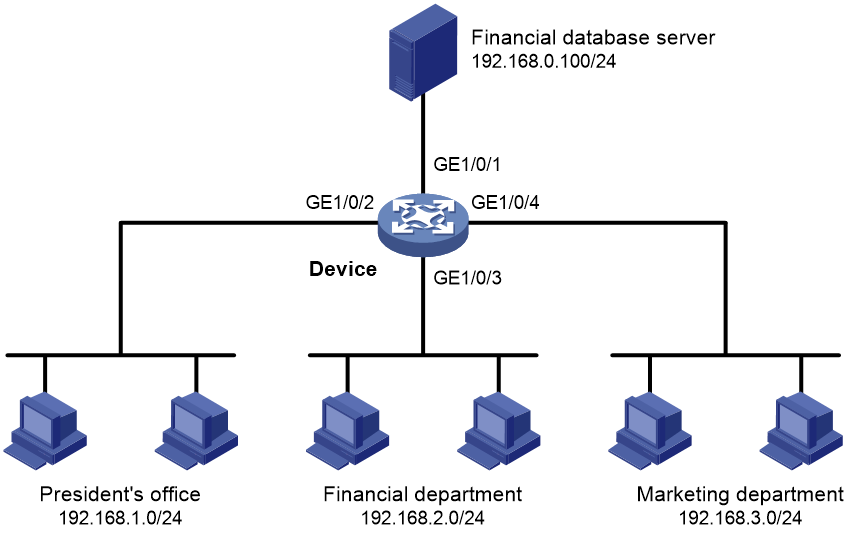
Network configuration
A company interconnects its departments through the device. Configure a packet filter to:
· Permit access from the President's office at any time to the financial database server.
· Permit access from the Finance department to the database server only during working hours (from 8:00 to 18:00) on working days.
· Deny access from any other department to the database server.
Figure 1 Network diagram
Procedure
# Create a periodic time range from 8:00 to 18:00 on working days.
<Device> system-view
[Device] time-range work 08:0 to 18:00 working-day
# Create an IPv4 advanced ACL numbered 3000.
[Device] acl advanced 3000
# Configure a rule to permit access from the President's office to the financial database server.
[Device-acl-ipv4-adv-3000] rule permit ip source 192.168.1.0 0.0.0.255 destination 192.168.0.100 0
# Configure a rule to permit access from the Finance department to the database server during working hours.
[Device-acl-ipv4-adv-3000] rule permit ip source 192.168.2.0 0.0.0.255 destination 192.168.0.100 0 time-range work
# Configure a rule to deny access to the financial database server.
[Device-acl-ipv4-adv-3000] rule deny ip source any destination 192.168.0.100 0
[Device-acl-ipv4-adv-3000] quit
# Apply IPv4 advanced ACL 3000 to filter outgoing packets on interface GigabitEthernet 1/0/1.
[Device] interface gigabitethernet 1/0/1
[Device-GigabitEthernet1/0/1] packet-filter 3000 outbound
[Device-GigabitEthernet1/0/1] quit
Verifying the configuration
# Verify that a PC in the Finance department can ping the database server during working hours. (All PCs in this example use Windows XP).
C:\> ping 192.168.0.100
Pinging 192.168.0.100 with 32 bytes of data:
Reply from 192.168.0.100: bytes=32 time=1ms TTL=255
Reply from 192.168.0.100: bytes=32 time<1ms TTL=255
Reply from 192.168.0.100: bytes=32 time<1ms TTL=255
Reply from 192.168.0.100: bytes=32 time<1ms TTL=255
Ping statistics for 192.168.0.100:
Packets: Sent = 4, Received = 4, Lost = 0 (0% loss),
Approximate round trip times in milli-seconds:
Minimum = 0ms, Maximum = 1ms, Average = 0ms
# Verify that a PC in the Marketing department cannot ping the database server during working hours.
C:\> ping 192.168.0.100
Pinging 192.168.0.100 with 32 bytes of data:
Request timed out.
Request timed out.
Request timed out.
Request timed out.
Ping statistics for 192.168.0.100:
Packets: Sent = 4, Received = 0, Lost = 4 (100% loss),
# Display configuration and match statistics for IPv4 advanced ACL 3000 on the device during working hours.
[Device] display acl 3000
Advanced IPv4 ACL 3000, 3 rules,
ACL's step is 5
rule 0 permit ip source 192.168.1.0 0.0.0.255 destination 192.168.0.100 0
rule 5 permit ip source 192.168.2.0 0.0.0.255 destination 192.168.0.100 0 time-range work (Active)
rule 10 deny ip destination 192.168.0.100 0
The output shows that rule 5 is active. Rule 5 and rule 10 have been matched four times as the result of the ping operations.
Packet filter configuration examples
Example: Configuring a packet filter
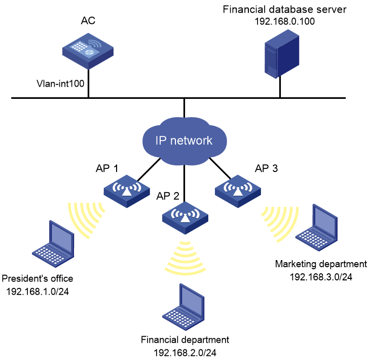
Network configuration
A company interconnects its departments through the AC. Configure a packet filter to:
· Permit access from the President's office at any time to the financial database server.
· Permit access from the Financial department to the database server only during working hours (from 8:00 to 18:00) on working days.
· Deny access from any other department to the database server.
Figure 2 Network diagram
Procedure
# Create a periodic time range from 8:00 to 18:00 on working days.
<AC> system-view
[AC] time-range work 08:0 to 18:00 working-day
# Create an IPv4 advanced ACL numbered 3000.
[AC] acl advanced 3000
# Configure a rule to permit access from the President's office to the financial database server.
[AC-acl-ipv4-adv-3000] rule permit ip source 192.168.1.0 0.0.0.255 destination 192.168.0.100 0
# Configure a rule to permit access from the Financial department to the database server during working hours.
[AC-acl-ipv4-adv-3000] rule permit ip source 192.168.2.0 0.0.0.255 destination 192.168.0.100 0 time-range work
# Configure a rule to deny access to the financial database server.
[AC-acl-ipv4-adv-3000] rule deny ip source any destination 192.168.0.100 0
[AC-acl-ipv4-adv-3000] quit
# Apply IPv4 advanced ACL 3000 to filter outgoing packets on interface VLAN-interface 100.
[AC] interface vlan-interface 100
[AC-Vlan-interface100] packet-filter 3000 outbound
[AC-Vlan-interface100] quit
Verifying the configuration
# Verify that a wireless client in the Financial department can ping the database server during working hours. (All clients in this example use Windows XP).
C:\> ping 192.168.0.100
Pinging 192.168.0.100 with 32 bytes of data:
Reply from 192.168.0.100: bytes=32 time=1ms TTL=255
Reply from 192.168.0.100: bytes=32 time<1ms TTL=255
Reply from 192.168.0.100: bytes=32 time<1ms TTL=255
Reply from 192.168.0.100: bytes=32 time<1ms TTL=255
Ping statistics for 192.168.0.100:
Packets: Sent = 4, Received = 4, Lost = 0 (0% loss),
Approximate round trip times in milli-seconds:
Minimum = 0ms, Maximum = 1ms, Average = 0ms
# Verify that a wireless client in the Marketing department cannot ping the database server during working hours.
C:\> ping 192.168.0.100
Pinging 192.168.0.100 with 32 bytes of data:
Request timed out.
Request timed out.
Request timed out.
Request timed out.
Ping statistics for 192.168.0.100:
Packets: Sent = 4, Received = 0, Lost = 4 (100% loss),
# Display configuration and match statistics for IPv4 advanced ACL 3000 on the AC during working hours.
[AC] display acl 3000
Advanced IPv4 ACL 3000, 3 rules,
ACL's step is 5
rule 0 permit ip source 192.168.1.0 0.0.0.255 destination 192.168.0.100 0
rule 5 permit ip source 192.168.2.0 0.0.0.255 destination 192.168.0.100 0 time-range work (4 times matched) (Active)
rule 10 deny ip destination 192.168.0.100 0 (4 times matched)
The output shows that rule 5 is active. Rule 5 and rule 10 have been matched four times as the result of the ping operations.
